
WiFi directional antenna & link budget planner
Calculate free space path loss, EIRP, fade margins, and Fresnel zone clearances for point-to-point wireless bridges and directional access point deployments.
Transmit antenna & radio setup
Cabling, receiver & threshold
Request an enterprise wireless bridge or directional WiFi site survey
Planning a high-density warehouse aisle rollout, campus building-to-building link, or outdoor hospitality WiFi expansion? Purple network engineers provide predictive 3D heat mapping, link budget verification, and hardware selection support.
A hotel has reliable fibre in the main building, but the staff block across the courtyard still depends on an unstable connection. A warehouse has an access point near the office, yet the loading bay and detached storage unit remain difficult to serve. In both cases, the instinct is often to buy a higher-gain antenna and expect more range.
That approach misses the engineering problem. WiFi directional antennas shape coverage. They concentrate radio energy towards a defined area, rather than distributing it broadly in every direction. That can improve a building-to-building link, reduce unwanted spillover, or serve a long corridor. It can also create dead zones, demand careful alignment, and fail completely when metalwork or dense construction blocks the path.
What Directional WiFi Antennas Are Actually For
Consider a hotel with a service corridor running from the main communications room towards an outdoor terrace. An omnidirectional antenna may waste energy behind the access point and send coverage into rooms or plant areas that don't need it. A panel or sector antenna can place the useful part of the cell along the corridor and terrace instead.
The same logic applies to a warehouse bridging to an outbuilding. A directional pair can create a focused wireless path across the yard, provided both ends have a clear route and compatible radio hardware. Ofcom notes that UK fixed wireless access systems commonly use external antennas at both the customer premises and the network hub, with directional designs selected to create beams and coverage areas that match demand-side needs in its review of future wireless broadband technologies.
Think in coverage shapes
A directional antenna earns its place when the required service area has a clear shape:
- A narrow path: A point-to-point link between buildings or across a courtyard.
- A long linear area: A hotel corridor, concourse, aisle, or outdoor seating route.
- A defined sector: A stadium edge, retail frontage, or venue terrace.
- A protected direction: A radio path aimed away from a noisy neighbouring access point.
An omni is usually the better choice when users move around the access point, occupy several rooms around it, or need consistent coverage in all directions. Mesh can be more appropriate where walls, floors, or changing layouts make a single fixed beam unreliable. Wired access points remain the sensible answer when construction materials block radio paths or when the site needs predictable capacity rather than a clever RF workaround.
Practical rule: Choose the area you need to illuminate before choosing the antenna gain.
Higher gain doesn't magically improve every client connection. It narrows the useful beam and may leave people outside that shape with weaker service than they had before. In hospitality, retail, and multi-tenant buildings, consistent coverage across the occupied space often matters more than maximum distance in one direction.
The Physics Behind Gain, Beamwidth and Polarisation
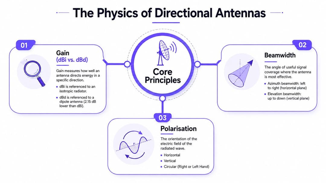
A directional antenna changes the shape of a coverage cell. Gain describes how strongly it concentrates radio energy in a chosen direction, while beamwidth defines the angular spread of useful signal. Polarisation describes the electric field's orientation. EIRP combines transmitter power, antenna gain, and cable or connector losses into the effective radiated output used for regulatory and link calculations.
These properties create practical trade-offs inside venues. A higher-gain antenna can place more energy along a corridor, façade, or point-to-point path, while reducing coverage outside that intended shape. Narrow beams can also limit interference from neighbouring SSIDs, but only when the mounting position and aiming are accurate. An omni remains the better fit when clients occupy several directions around the access point.
Reading the datasheet
- dBi and dBd: dBi expresses gain relative to an ideal isotropic radiator. dBd uses a half-wave dipole as its reference. Check the manufacturer's reference scale before comparing products.
- Beamwidth: Read both azimuth and elevation values. A narrow elevation beam can suit a long, level site, but clients above or below that plane may receive weaker service.
- Polarisation: MIMO radios commonly use multiple polarisation orientations to separate spatial streams. The radio and antenna arrangement must preserve the intended relationship instead of placing every element at an arbitrary angle.
- EIRP: Transmit power, antenna gain, and cable or connector loss determine the effective radiated figure. A higher-gain antenna may require lower radio power to remain within the applicable limit.
Ofcom's UK spectrum material shows why gain figures cannot be assessed in isolation. Its 2023 review says fixed wireless networks have typically operated in the lightly licensed 5.8 GHz band, where regulations permit a maximum transmit power of 4 Watts EIRP, or 36 dBm in the relevant deployments. Directionality helps concentrate energy while staying within that ceiling.
A vendor datasheet for a 5 GHz directional model reports 12 dBi gain across 5150 to 5725 MHz, a 7 degree elevation beamwidth, VSWR under 1.5, and 50 ohm impedance, as shown in the manufacturer's technical data. The narrow vertical lobe can reduce spillover, but it leaves less tolerance for poor mounting, uneven terrain, or antenna movement.
Comparing the Main Antenna Families for WiFi
A venue rollout can contain a courtyard, a metal-lined hall, and corridors full of neighbouring SSIDs. One antenna pattern will not serve all three areas well. Choose the required coverage shape first, then select gain, mounting hardware, and radio power to support it. A high-gain dish aimed across an open courtyard suits a dedicated link, while an omni may be the smarter choice for users moving around a central room.
| Type | Typical gain | Approx. beamwidth | Best-fit use | Watch out for |
|---|---|---|---|---|
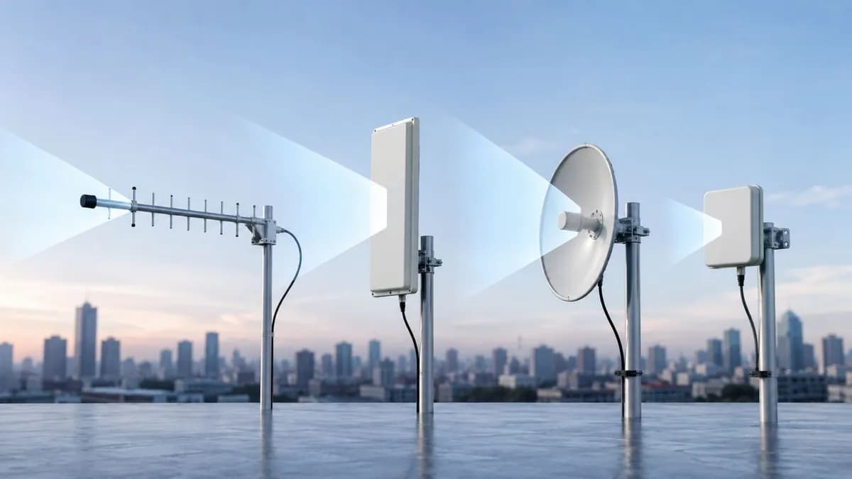
| Yagi | Moderate to high | Narrow, often asymmetric | Rural links and point-to-point connections | Wind loading, alignment, and side lobes |
| Panel | Moderate to high | Controlled sector or wedge | Corridors, façades, outbuildings, terraces | Dead zones outside the face |
| Parabolic dish | High to very high | Very narrow pencil beam | Long, clear point-to-point backhaul | Precise alignment and physical obstruction |
| Patch | Low to moderate | Focused, compact pattern | Integrated outdoor units and wall-mounted APs | Limited flexibility if the built-in pattern doesn't fit |
| Sector | Moderate to high | Wide horizontal slice | Stadium concourses, yards, and venue edges | Overlap planning and interference between sectors |
What each family does well
Yagi antennas fit clean, elongated paths where the mounting point and physical size are manageable. They can connect a remote building, but their narrow pattern does not suit broad user coverage around the installation. Side lobes and wind movement also deserve attention during alignment.
Panels are the practical general-purpose option for targeted coverage. Mounted on a building, a panel can face a courtyard, terrace, corridor, or outbuilding while reducing energy behind the wall. The face still needs a realistic view of the service area, particularly where reinforced walls, shelving, or other metal structures interrupt the path.
Parabolic dishes produce the narrowest beam in this group. Reserve them for dedicated links with clear endpoints. They are a poor fit for public areas where clients may appear across a wide angle, and a small alignment error can materially reduce the received signal.
Patch antennas are compact and often integrated into outdoor access-point assemblies. They make sense when the enclosure, radio, connectors, and mounting system were designed together. Their built-in pattern can limit later changes if the venue layout shifts.
Sector antennas divide coverage into broad slices. They work well along stadium concourses, yards, and venue edges when one omni would create excessive unwanted coverage. Plan channel use, transmit power, and cell overlap together, especially where neighbouring SSIDs already raise the interference floor.
External antennas and directional designs are used in fixed wireless deployments to form beams and coverage areas around the service requirement, as shown in fixed wireless access deployments. The operational rule is straightforward, choose beam shape first and gain second. Check the applicable EIRP ceiling before increasing gain, then verify that the selected pattern matches where clients operate.
Reading and Building a Simple Link Budget
A link budget tells you whether the radio path has enough margin before installation surprises appear. Build it in a spreadsheet with four groups of inputs:
- Free-space path loss: Calculate the loss for the distance and operating frequency. The same distance produces more free-space loss at 5 GHz than at 2.4 GHz because the wavelength is shorter.
- Transmit power: Use the radio's actual configured output, not the maximum printed on a product page.
- Antenna gains: Add the transmitting and receiving antenna gains, using the same reference scale throughout.
- System losses: Subtract coaxial cable, connector, lightning protection, and any other inline losses.
The result is an estimated received level. Compare it with the radio's receive sensitivity for the modulation and channel width you want to sustain, then leave practical margin for rain, movement, interference, imperfect alignment, and construction changes. Don't design a link that only works at the edge of its theoretical sensitivity.
For a simplified building-to-building calculation, start with the free-space loss for 200 metres at both 2.4 GHz and 5 GHz, then add the configured transmit power and gains at each end. Subtract the complete cable and connector path, not just the headline coax length. The difference between the two frequency calculations shows why a 5 GHz link needs careful antenna selection and alignment.
The Purple access point calculator can help with the wider access-point planning exercise, but it doesn't replace a radio link budget for a dedicated bridge. Keep the calculations separate. One describes client coverage and capacity, while the other tests a specific RF path.
A few extra dB of antenna gain can recover some path loss, but only inside the intended beam. A longer path, Fresnel obstruction, wet connector, or nearby interferer can consume that margin quickly. Treat the budget as a design screen, then validate the installed link with measured RSSI, negotiated data rates, and sustained throughput.
Where Directional Antennas Actually Win in Real Deployments
The strongest use case is a point-to-point bridge. Two buildings may have a clear roofline, but trenching fibre could be disruptive or impractical. A matched directional pair can carry the connection across the gap while limiting radiation outside the route. Warehouses, remote staff blocks, car parks, and temporary venue structures can all fit this pattern when the path remains stable.
The second use case is targeted venue coverage. A panel can face an outdoor dining area from a building façade. A sector can serve a concourse or terrace without treating the entire surrounding site as one large cell. In a hotel or build-to-rent property, the right beam can follow the occupied floor plan more closely than an omni mounted in a central plant room.

Directionality can improve the RF environment
Adding access points doesn't always solve a noisy venue. If neighbouring SSIDs, reflective surfaces, and poorly controlled overlap already raise contention, more transmitters can make planning harder. A directional antenna may help a receiver favour a selected path, but it won't remove interference that sits inside the same beam or comes from the intended service area.
That distinction matters because antenna choice changes network behaviour, not just signal reach. Ulster University research on 2.4 GHz WLAN found different traffic statistics and idle-time distributions when comparing omni-directional and directional antennas in an indoor environment, as described in the UK WLAN spectrum occupancy material. For a dense office, venue, or multi-occupancy building, engineers should measure channel occupancy and contention rather than judge success only by signal-strength bars.
Outdoor product ranges now include designs for 2.4 GHz, 5 GHz, and wider bands reaching 7.2 GHz, along with MIMO and sector-style products, as shown in Solwise's outdoor antenna catalogue. That broadens the design choices for WiFi 6E and WiFi 7-era sites, but it also makes compatibility checks more important. A narrow patch, a broad sector, and an integrated outdoor radio solve different coverage-shape problems.
Choosing the Right Antenna for Your Site
Procurement should begin with the site survey, not the product filter. First identify the radios, their supported bands, connector arrangement, and whether the access point expects external antenna control. An antenna covering the right frequency but not matching the radio's MIMO chain or connector layout isn't a usable option.
A practical shortlist
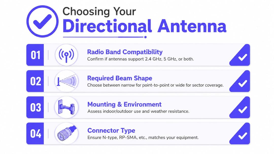
- Radio band compatibility: Confirm whether the deployment uses 2.4 GHz, 5 GHz, 6 GHz, or multiple bands. Don't assume a 5 GHz antenna covers every channel your radio may select.
- Required beam shape: Choose a narrow beam for a defined point-to-point route, a panel for a controlled face, or a sector for a wider slice of a venue.
- Mounting and environment: Check wall, pole, roof, bracket, clearance, wind exposure, and outdoor weather resistance. A building survey should identify metal cladding, plant rooms, reinforced concrete, and other likely obstructions.
- Cable path: Every connector, surge protector, and length of coax consumes link margin. Put the radio close to the antenna where practical, rather than accepting a long cable run by default.
- Connector and radio ecosystem: Match N-type, RP-SMA, or the equipment's specified connector, and confirm the access point supports the intended antenna configuration. For broader network planning, use the WiFi buying guide alongside the radio manufacturer's installation documentation.
- Protection and serviceability: Specify surge protection, grounding, connector weatherproofing, and a PoE pass-through plan for outdoor access points before the installer arrives.
UK rules reinforce the need to treat gain as an engineering and licensing input. Ofcom's licensing update distinguishes antenna gain ranges by band, including an omni-antenna range of 0 to 16 dBi in the 1.8 GHz and 3.8 to 4.2 GHz bands, and 16 to 29 dBi in the 26 GHz band, as set out in its spectrum management antenna guidance. The exact requirement depends on the service and licence, so document the calculation rather than relying on a vendor's default.
Shortlist two or three antennas that fit the beam, mounting, band, and compliance requirements. Only then compare gain, price, and availability.
Installation and Alignment Best Practices
Treat installation as part of the RF design, not as a mounting task. Before drilling, confirm the intended coverage shape and inspect the path between both ends. Review roof plans, nearby structures, mature trees, plant equipment, and likely future construction. A visual line of sight helps, but the survey should also assess clearance around the direct path, reflections from metal surfaces, and whether the mounting structure can hold alignment.
Use a rigid surface and a bracket rated for the antenna's load and orientation. Keep coaxial runs short, supported, and within the specified bend radius. Protect outdoor connectors from water ingress, and include surge protection and grounding in the site design. Moisture at a connector adds loss that can resemble a radio or alignment fault.
Align the path methodically
If the platform permits, begin with both radios unassociated. Sweep one antenna slowly across the expected bearing while monitoring received level and noise. Repeat at the other end, select the strongest stable position, then tighten the hardware without shifting the angle. Confirm the result in the radio diagnostics and with a sustained throughput test under representative channel conditions.
Record the commissioning state:
- Alignment angles and mounting orientation.
- RSSI and noise readings at handover.
- Expected throughput and channel configuration.
- Cable and connector details.
- Conditions that require a recheck, such as building work, bracket movement, or severe weather exposure.
Use the connectors library to verify connector terminology before ordering adapters or patch leads. Every unnecessary adapter adds another failure point and makes weatherproofing harder.
For repeatable operations, attach photos of the bracket, cable routing, and final antenna bearing to the site record. If neighbouring SSIDs or venue activity changes the noise floor, repeat the validation rather than adjusting alignment by RSSI alone.
A well-aligned, modest antenna usually outperforms a premium model pointed several degrees away from its partner. Commission alignment as a measured handover task, not as the final twist of a bracket after the installer has left.
Common Mistakes, Troubleshooting and Where They Fit in Secure WiFi
The most common mistake is chasing the highest gain figure. Gain without the correct beamwidth can move the problem rather than solve it. Users outside the beam may lose coverage, while users inside a metal-heavy building still face blockage, reflection, and attenuation.
A second mistake is assuming that directionality can overcome poor site geometry. Dense walls, reinforced structures, shelving, plant rooms, and metal façades can block the intended path. If the coverage hole is caused by materials, move the access point, add a wired node, or redesign the cell. Don't keep increasing antenna gain and hope the wall becomes transparent.
Troubleshoot in the right order
- Inspect connectors and cable: Check seating, damage, water ingress, adapters, and surge devices.
- Confirm alignment: Recheck both ends, mounting rigidity, and any recent work on the roof or wall.
- Review RF conditions: Compare noise, channel occupancy, neighbouring SSIDs, channel width, and transmit power.
- Check compliance: Recalculate EIRP with the installed antenna, cable, and radio settings. Ofcom requires directional-antenna submissions for certain licensed systems to include horizontal and vertical radiation patterns in 5-degree increments, as well as gain and tilt, because those details feed interference modelling and coverage approval in its business radio technical criteria.
- Test the client experience: Measure roaming, throughput, latency, and reliability where people use the service.
Directional backhaul and identity-based WiFi solve different layers of the same venue problem. The antenna carries traffic between sites or shapes the RF cell. Purple provides passwordless guest and staff access, with integrations across platforms such as Meraki, Aruba, Ruckus, Mist, and UniFi. Keep those responsibilities separate in the design. A strong link still needs secure onboarding and an access policy that suits the people using the venue.
Purple can help venues connect directional backhaul and targeted coverage to secure, passwordless WiFi for guests, staff, and multi-tenant users. Visit Purple to assess how its identity-based networking platform can fit your existing wireless infrastructure and rollout plan.