Cómo Medir la Intensidad de Señal y Cobertura WiFi
Esta guía de referencia técnica equipa a los técnicos de red y gerentes de TI con un marco práctico y neutral respecto al proveedor para auditar la intensidad de señal y cobertura WiFi utilizando herramientas de RSSI, SNR y mapeo de calor. Cubre la física de la propagación de RF, una metodología de levantamiento paso a paso y escenarios de remediación reales extraídos de entornos de hotelería y logística. Optimizar la cobertura reduce directamente los gastos generales del servicio de asistencia, apoya los requisitos de cumplimiento y desbloquea los datos de telemetría necesarios para impulsar la inteligencia operativa en todos los recintos empresariales.
Escucha esta guía
Ver transcripción del podcast

Resumen Ejecutivo
Para gerentes de TI y arquitectos de red que supervisan recintos a gran escala —ya sean de hotelería , minoristas , estadios o entornos del sector público—, ofrecer WiFi consistente y de alto rendimiento es un requisito operativo básico, no un diferenciador. La mala intensidad de señal y las brechas de cobertura impactan directamente la productividad del personal, la eficiencia operativa y la experiencia del huésped. Esta guía proporciona un marco práctico y neutral respecto al proveedor para medir la intensidad de señal WiFi, interpretar las métricas críticas de RSSI (Received Signal Strength Indicator) y SNR (Signal-to-Noise Ratio), y desplegar herramientas de mapeo de calor para auditorías de cobertura exhaustivas. Al estandarizar cómo sus equipos miden y remedian las redes inalámbricas, puede mitigar riesgos, asegurar la alineación con estándares como PCI DSS e IEEE 802.1X, y optimizar el retorno de su inversión en infraestructura inalámbrica. La guía también aborda los costos ocultos de rendimiento que surgen de un diseño de RF deficiente —costos explorados en profundidad en El Costo Oculto de los Datos de Telemetría en WLANs Corporativas .
Análisis Técnico Detallado: RSSI, SNR y la Física de la Cobertura
Medir la cobertura WiFi va mucho más allá de verificar las barras de señal en un dispositivo. Esas barras son una representación arbitraria y definida por el fabricante de la calidad de la señal y nunca deben usarse como una línea base de ingeniería. La medición efectiva de la cobertura requiere datos de RF empíricos, recopilados sistemáticamente e interpretados frente a umbrales de rendimiento definidos.
RSSI: La Línea Base de Cobertura
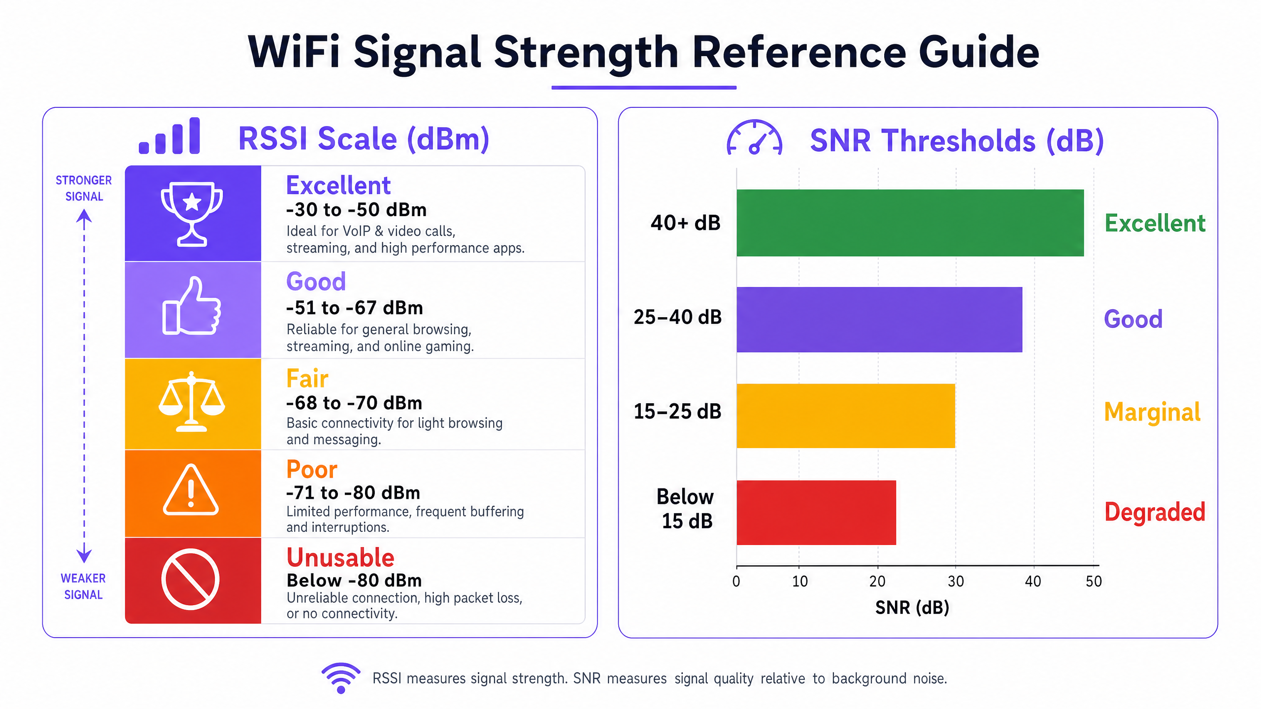
RSSI es la métrica fundamental para medir el nivel de potencia de la señal de RF recibida por el dispositivo cliente. Se expresa en decibelios relativos a un milivatio (dBm). Debido a que opera en una escala negativa, los valores más cercanos a cero representan una señal más fuerte. La escala es logarítmica: cada cambio de 3 dB representa una duplicación o reducción a la mitad de la potencia de la señal, lo que significa que la diferencia entre -67 dBm y -73 dBm no es incremental —es una reducción de cuatro veces en la potencia recibida.
Los siguientes umbrales representan los rangos operativos prácticos para implementaciones empresariales:
| Rango RSSI | Clasificación | Aplicaciones Adecuadas |
|---|---|---|
| -30 a -50 dBm | Excelente | VoIP, videoconferencia HD, datos de alto rendimiento |
| -51 a -67 dBm | Bueno | Todas las aplicaciones empresariales estándar |
| -68 a -70 dBm | Marginal | Navegación web básica, correo electrónico |
| -71 a -80 dBm | Pobre | Conectividad intermitente, alta pérdida de paquetes |
| Por debajo de -80 dBm | Inutilizable | Caídas de conexión, rendimiento inutilizable |
El umbral de -67 dBm es el mínimo estándar de la industria para una conectividad empresarial confiable. La mayoría de los dispositivos cliente empresariales están programados para iniciar un escaneo de roaming cuando la señal cae por debajo de este nivel, lo que lo convierte en el parámetro de diseño crítico para la planificación de la superposición de celdas.
SNR: El Multiplicador de Calidad
Un RSSI fuerte es una condición necesaria pero insuficiente para un buen rendimiento de la red. SNR mide la diferencia entre la intensidad de la señal recibida y el nivel de ruido de RF de fondo, expresado en decibelios (dB). Determina el esquema de modulación y codificación (MCS) que los dispositivos pueden negociar con el AP, lo que rige directamente el rendimiento alcanzable. Wi-Fi 6 (802.11ax) soporta hasta 1024-QAM, pero eso requiere un SNR de aproximadamente 35 dB o superior. Con valores bajos de SNR, los dispositivos recurren a esquemas de modulación de orden inferior, reduciendo drásticamente el rendimiento.
| Rango SNR | Clasificación | Impacto en el Rendimiento |
|---|---|---|
| > 40 dB | Excelente | Tasas de datos máximas (1024-QAM alcanzable) |
| 25 – 40 dB | Bueno | Operación confiable de alto rendimiento |
| 15 – 25 dB | Marginal | Tasas de datos reducidas, reintentos aumentados |
| < 15 dB | Degradado | Pérdida significativa de paquetes, inestabilidad de conexión |
Interferencia Co-canal y de Canal Adyacente
En entornos de alta densidad —un centro de conferencias durante un evento importante, una tienda minorista en días de mayor actividad comercial— la interferencia es la principal limitación de la capacidad de la red. La Interferencia Co-canal (CCI) ocurre cuando múltiples APs transmiten en el mismo canal dentro del alcance mutuo. Bajo el protocolo 802.11 CSMA/CA, los dispositivos deben esperar a que el canal esté libre antes de transmitir, creando contención y reduciendo el rendimiento efectivo. La Interferencia de Canal Adyacente (ACI) surge cuando los APs utilizan canales superpuestos —por ejemplo, los canales 1 y 2 en la banda de 2.4 GHz— causando superposición espectral y degradación de la señal.
La banda de 2.4 GHz ofrece solo tres canales no superpuestos (1, 6 y 11), lo que la hace estructuralmente inadecuada para implementaciones de alta densidad. La banda de 5 GHz proporciona hasta 24 canales de 20 MHz no superpuestos, y la banda de 6 GHz (Wi-Fi 6E/7) añade 59 canales adicionales, lo que las convierte en el objetivo correcto para la planificación de capacidad empresarial.
Guía de Implementación: Realización de una Auditoría de Cobertura WiFi
Una auditoría de cobertura estructurada es la base de cualquier programa de optimización. La siguiente metodología es neutral respecto al proveedor y aplicable a entornos desde un hotel de 50 habitaciones hasta un estadio de 60,000 asientos.
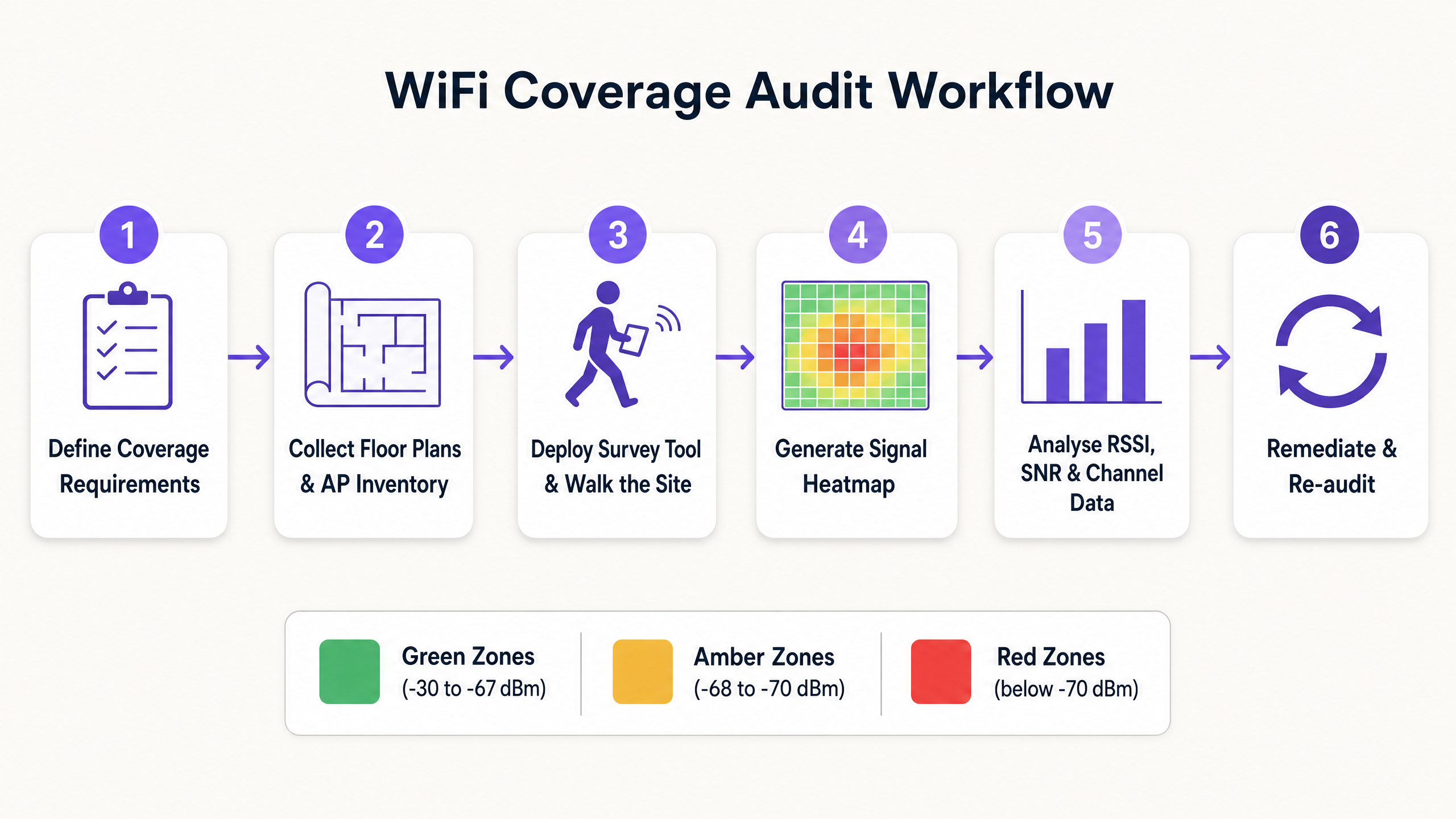
Paso 1: Definir los Requisitos de Cobertura y los Umbrales de Rendimiento
Antes de realizar cualquier levantamiento, documente los requisitos específicos para el entorno. Un almacén que utiliza escáneres de códigos de barras tiene requisitos fundamentalmente diferentes a los de un entorno clínico que soporta dispositivos de monitoreo de pacientes o un centro de conferencias que ejecuta videoconferencias de alta densidad. Defina los mimínimos aceptables de RSSI y SNR para cada tipo de aplicación, e identificar cualquier requisito de cumplimiento (por ejemplo, PCI DSS para sistemas de pago minoristas, o estándares adyacentes a HIPAA para entornos de atención médica ).
Paso 2: Recopilar planos de planta e inventario de AP
Obtenga planos de planta precisos y a escala para todas las áreas dentro del alcance. Impórtelos a su herramienta de estudio y documente el inventario actual de AP, incluyendo modelo, versión de firmware, configuraciones de potencia de transmisión y asignaciones de canal. Esta línea de base es esencial para correlacionar los hallazgos del estudio con los parámetros de configuración.
Paso 3: Seleccionar el tipo de estudio adecuado
Tres metodologías de estudio sirven para diferentes propósitos:
Estudio predictivo: Utiliza modelado de software para simular el entorno de RF basándose en planos de planta, materiales de pared y ubicación de AP. Es esencial para implementaciones nuevas y rediseños importantes. La precisión depende de la calidad de la base de datos de materiales de construcción utilizada.
Estudio pasivo: El dispositivo de estudio escucha todo el tráfico de RF en el entorno, capturando tramas de baliza de cada AP visible para mapear RSSI, utilización de canal y presencia de dispositivos no autorizados. Este es el método estándar para auditar la cobertura existente y generar mapas de calor. No requiere que el dispositivo de estudio se asocie con la red.
Estudio activo: El dispositivo de estudio se asocia con la red objetivo y transmite datos activamente (típicamente a través de iPerf o ICMP) para medir el rendimiento real, la latencia, el jitter y el rendimiento de roaming. Este es el método definitivo para validar que la red funciona según lo diseñado bajo carga.
Paso 4: Ejecutar el estudio de recorrido
Para estudios pasivos y activos, el técnico recorre toda el área de cobertura a un ritmo constante, típicamente de 0.5 a 1 metro por segundo, asegurando que la herramienta de estudio capture suficientes puntos de datos por metro cuadrado. Preste especial atención a las áreas con fuentes de atenuación conocidas: pilares de concreto, estanterías metálicas, huecos de ascensores y áreas con alto contenido de agua (por ejemplo, acuarios, jardineras grandes).
Paso 5: Generar e interpretar mapas de calor
Después del estudio, genere los siguientes mapas de calor como mínimo:
- Mapa de calor RSSI: Identifica zonas muertas y brechas de cobertura en relación con su umbral definido.
- Mapa de calor SNR: Destaca áreas donde la interferencia está degradando la calidad de la señal.
- Mapa de calor de interferencia de canal: Identifica puntos críticos de CCI y ACI.
- Mapa de calor de superposición de cobertura de AP: Valida que la superposición de celdas es suficiente para un roaming sin interrupciones.
Al revisar los mapas de calor, asegúrese de que los bordes de las celdas de cobertura mantengan una superposición del 15 al 20% en el umbral de -67 dBm. Una superposición insuficiente resulta en fallas de roaming; una superposición excesiva con alta potencia de transmisión resulta en CCI.
Paso 6: Remediar y reauditar
Documente todos los hallazgos y priorice las acciones de remediación por impacto. Los pasos comunes de remediación incluyen ajustar la potencia de transmisión de AP, modificar las asignaciones de canal, reubicar AP para superar la atenuación, agregar AP para llenar brechas de cobertura e implementar band steering para dirigir clientes capaces a 5 GHz. Después de la remediación, realice un estudio de validación para confirmar que los cambios han logrado el resultado deseado.
Mejores prácticas para la optimización de WiFi empresarial
Diseñe para la capacidad, no solo para la cobertura. En entornos empresariales modernos, el desafío rara vez es proporcionar una señal; es soportar cientos de dispositivos concurrentes con un rendimiento consistente. El diseño de alta densidad requiere más AP que operen con menor potencia de transmisión, con patrones de reutilización de canal más ajustados. Esto es particularmente relevante en lugares de hospitalidad y centros de transporte donde la densidad de dispositivos puede ser extrema.
Estandarice en 5 GHz y 6 GHz. La banda de 2.4 GHz está estructuralmente congestionada. Dirija todos los dispositivos corporativos y del personal capaces a las bandas de 5 GHz o 6 GHz utilizando band steering o separación de SSID. Reserve 2.4 GHz para dispositivos IoT heredados que no pueden operar en frecuencias más altas. Para un análisis detallado del impacto en el rendimiento del tráfico de dispositivos no administrados en WLAN corporativas, consulte El costo oculto de los datos de telemetría en las WLAN corporativas .
Implemente una autenticación robusta. Asegure que las redes corporativas estén protegidas con IEEE 802.1X y WPA3-Enterprise. Para el acceso de invitados y visitantes, implemente una solución de Guest WiFi gestionada con un Captive Portal seguro. Como se explora en Cómo un asistente de Wi-Fi habilita el acceso sin contraseña en 2026 , los marcos de autenticación modernos pueden eliminar la sobrecarga de la gestión de contraseñas mientras mantienen el cumplimiento de la seguridad.
Adopte el monitoreo continuo. Una auditoría puntual captura el entorno de RF en un solo momento. El entorno inalámbrico es dinámico: surgen nuevas fuentes de interferencia, las poblaciones de dispositivos cambian y las modificaciones físicas alteran los patrones de propagación. Implemente una plataforma de WiFi Analytics para monitorear continuamente la salud de la red, el rendimiento del cliente y las métricas de cobertura. Esto también permite la recopilación de datos de afluencia y tiempo de permanencia que respaldan iniciativas de inteligencia operativa más amplias, incluidas aquellas alineadas con programas de ciudades inteligentes como los liderados por Iain Fox en Purple .
Solución de problemas y mitigación de riesgos
Cuando surgen problemas de cobertura o rendimiento, un enfoque de diagnóstico estructurado previene diagnósticos erróneos y esfuerzos de remediación desperdiciados.
1. Determine el alcance. ¿El problema afecta a un solo usuario, a un área definida o a todo el lugar? Un problema de un solo usuario casi siempre apunta a un problema del dispositivo cliente (controlador, hardware o configuración de roaming). Un problema específico de un área apunta al entorno de RF. Un problema que afecta a todo el lugar apunta a la infraestructura (controlador, DHCP, DNS o conectividad ascendente).
2. Verifique la capa física. Confirme que los AP afectados están recibiendo suficiente energía PoE, que el cableado está intacto y que los AP no han sido obstruidos físicamente o reubicados desde la última encuesta. Una proporción sorprendentemente alta de problemas de rendimiento se remonta a cambios físicos en el entorno.
3. Analice el entorno de RF. Utilice un analizador de espectro para identificar fuentes de interferencia que no sean WiFi. Los hornos de microondas, las cámaras CCTV inalámbricas y los dispositivos Bluetooth que operan en la banda de 2.4 GHz son culpables comunes. En entornos industriales, los variadores de frecuencia y otros equipos de control de motores pueden generar un ruido de RF de banda ancha significativo.
4. Revise la configuración del AP. Verifique los niveles de potencia de transmisión, las asignaciones de canales y las versiones de firmware. Confirme que las políticas de gestión dinámica de radio (DRM) funcionan correctamente y que ningún AP ha vuelto a la configuración predeterminada de alta potencia.
5. Examine las capacidades del cliente. Los dispositivos cliente más antiguos con controladores inalámbricos desactualizados, o los dispositivos con configuraciones agresivas de ahorro de energía, con frecuencia presentan problemas de conectividad independientemente de la calidad de la red. Mantenga un registro de hardware cliente y versiones de controladores aprobados para dispositivos gestionados por la empresa.
ROI e Impacto Empresarial
Invertir en auditorías y optimización regulares de WiFi ofrece un valor empresarial medible y cuantificable en múltiples dimensiones.
Productividad del personal. La eliminación de zonas muertas e interferencias garantiza que el personal pueda acceder a aplicaciones operativas críticas sin interrupciones, ya sea la gestión de inventario en un piso de retail , el acceso a registros de pacientes en una instalación de healthcare o la coordinación operativa en un centro de transport . Incluso una reducción de 5 minutos por día en los retrasos relacionados con la conectividad en una operación de 200 personas representa más de 170 horas de productividad recuperada al año.
Reducción de la sobrecarga de soporte. Una red estable y bien diseñada genera significativamente menos tickets de mesa de ayuda. Los problemas de conectividad WiFi se encuentran constantemente entre las tres principales categorías de solicitudes de soporte de TI en grandes organizaciones. Resolver los problemas de RF subyacentes, en lugar de abordar repetidamente los síntomas, ofrece reducciones sostenidas en el volumen de soporte.
Cumplimiento y mitigación de riesgos. Para organizaciones sujetas a PCI DSS (entornos de pago minorista), GDPR (cualquier organización que procese datos personales a través de WiFi) o estándares específicos del sector, una red inalámbrica documentada y auditada regularmente es un requisito de cumplimiento. La detección de APs no autorizados, habilitada por herramientas de encuesta pasiva y monitoreo continuo, es un requisito específico de PCI DSS.
Inteligencia Operacional. Una red optimizada proporciona datos de telemetría precisos y de alta fidelidad. Estos datos, que cubren el recuento de dispositivos, los tiempos de permanencia y los patrones de movimiento, son la base del análisis de ubicaciones. Como demuestra la capacidad de mapas sin conexión de Purple ( Purple lanza el modo de mapas sin conexión para una navegación fluida y segura a los puntos de acceso WiFi ), una red inalámbrica bien instrumentada permite servicios de ubicación avanzados que impulsan tanto la eficiencia operativa como la experiencia del visitante.
Definiciones clave
RSSI (Received Signal Strength Indicator)
A measurement of the power level of the RF signal received by the client device, expressed in negative decibels relative to a milliwatt (dBm). Values closer to zero indicate a stronger signal.
The primary metric for assessing basic coverage. Used to identify dead zones and validate that signal strength meets the minimum threshold for the target application.
SNR (Signal-to-Noise Ratio)
The difference between the received signal strength (RSSI) and the background RF noise floor, expressed in decibels (dB). Determines the modulation scheme devices can negotiate, directly governing throughput.
Critical for diagnosing performance issues in environments where RSSI appears adequate but throughput is poor. The key metric for identifying interference-related degradation.
Co-Channel Interference (CCI)
Interference caused when multiple APs within range of each other transmit on the same channel, forcing devices to defer transmission under the 802.11 CSMA/CA protocol.
The primary cause of capacity degradation in high-density deployments. Mitigated through careful channel planning, dynamic radio management, and reducing AP transmit power.
Adjacent Channel Interference (ACI)
Interference caused by APs transmitting on spectrally overlapping channels (e.g., channels 1 and 2 in the 2.4 GHz band), causing signal bleed between channels.
Prevented by using only non-overlapping channels: 1, 6, and 11 in the 2.4 GHz band. Not an issue in the 5 GHz or 6 GHz bands when using 20 MHz channel widths.
Attenuation
The loss of RF signal strength as waves pass through physical objects. Attenuation varies significantly by material: glass causes ~2 dB loss, drywall ~3 dB, concrete ~10–15 dB, and metal causes near-total reflection.
Must be factored into predictive surveys and physical AP placement decisions. Particularly significant in warehouses, hospitals, and venues with metal infrastructure.
Passive Survey
A site survey method in which the surveying tool listens to all RF traffic without associating with any network, capturing beacon frames to map RSSI, channel utilisation, and rogue AP presence.
The standard method for auditing existing coverage and generating heatmaps. Does not require network credentials and can detect all visible APs including unauthorised devices.
Active Survey
A site survey method in which the surveying device associates with the target network and actively transmits data to measure real-world throughput, latency, jitter, and roaming performance.
Used to validate actual network performance under simulated load conditions. Essential for applications with strict latency or throughput requirements, such as VoIP or AGV control systems.
Roaming (802.11r / Fast BSS Transition)
The process of a client device transitioning from one AP to another as it moves through a venue. 802.11r (Fast BSS Transition) reduces the authentication overhead during roaming, minimising the transition latency.
Requires careful cell overlap design (15–20% at -67 dBm) to ensure seamless transitions. Critical for voice, video, and real-time control applications. Sticky client behaviour — where devices hold onto a weak signal — is a common roaming failure mode.
Ejemplos resueltos
A 300-room luxury hotel is experiencing frequent guest and staff complaints about dropped VoIP calls and poor video streaming in the newly renovated West Wing. The IT team has confirmed via the network management system that all APs in the wing are online and reporting normal status.
Step 1: Deploy a technician to conduct a combined passive and active site survey of the West Wing using a professional survey tool. Step 2: Generate an RSSI heatmap — this shows signal strength is generally above -67 dBm throughout the wing, ruling out basic coverage gaps. Step 3: Generate an SNR heatmap — this reveals significant areas where SNR drops below 15 dB, particularly in corridors and meeting rooms. Step 4: Generate a Channel Interference heatmap — this identifies severe Co-Channel Interference (CCI) caused by the newly installed APs operating at maximum transmit power (23 dBm) on the same 5 GHz channels as adjacent APs. Step 5: Remediation — implement a dynamic radio management (DRM) profile to automatically reduce transmit power to 8–12 dBm and assign non-overlapping channels. Disable 2.4 GHz radios on every other AP to reduce CCI on the legacy band. Step 6: Conduct a validation active survey to confirm that SNR has improved above 25 dB across the wing and that roaming performance meets the VoIP threshold.
A large retail distribution centre is deploying a fleet of autonomous guided vehicles (AGVs) that require continuous, low-latency WiFi connectivity. During initial testing, the AGVs frequently disconnect when transitioning between aisles, causing operational disruptions.
Step 1: Document the AGV connectivity requirements — minimum RSSI of -65 dBm, SNR above 25 dB, and roaming latency below 50 ms for the control protocol. Step 2: Conduct an active survey along all planned AGV routes, with the survey tool configured to simulate the AGV client profile. Step 3: Analysis reveals that the existing APs, mounted 15 metres high on the ceiling with omnidirectional antennas, provide adequate signal in empty aisles but the RSSI drops to -78 dBm when aisles are fully stocked with metal shelving and liquid products — materials with high RF attenuation coefficients. Step 4: The channel plan also shows CCI between APs sharing channels in adjacent aisles. Step 5: Remediation — redesign the WLAN using directional patch antennas (e.g., 8 dBi patch) mounted at the ends of aisles at a height of 2 metres, directing RF energy down the corridors. Implement a dedicated SSID for AGVs with 802.11r (Fast BSS Transition) enabled to reduce roaming latency. Step 6: Validate with an active survey along all AGV routes under full inventory load conditions.
Preguntas de práctica
Q1. A hospital IT manager is receiving complaints from nursing staff about dropped calls on their VoIP handsets in a specific ward. A passive survey confirms that RSSI throughout the ward is consistently between -55 dBm and -62 dBm. What is the most likely root cause, and what diagnostic step should be taken next?
Sugerencia: RSSI is well within the acceptable range. Consider what other metric determines whether that signal can support VoIP traffic.
Ver respuesta modelo
The issue is almost certainly low SNR rather than a coverage gap. An RSSI of -55 to -62 dBm is excellent, so the signal is not the problem. The next step is to generate an SNR heatmap for the ward. Low SNR in this scenario is likely caused by Co-Channel Interference (CCI) from adjacent APs, or potentially from non-WiFi interference sources such as medical equipment operating in the 2.4 GHz band. A spectrum analysis should also be conducted to identify non-WiFi interference sources.
Q2. You are designing a WLAN for a high-density conference centre that will host events with up to 2,000 concurrent devices. Your predictive survey indicates that 60 APs are required to achieve the necessary capacity. How should you approach the 2.4 GHz radio configuration?
Sugerencia: Consider the number of non-overlapping channels available in the 2.4 GHz band relative to the number of APs.
Ver respuesta modelo
The 2.4 GHz radios on the majority of APs should be disabled. With only three non-overlapping channels (1, 6, and 11) available in the 2.4 GHz band, deploying 60 APs all transmitting on 2.4 GHz in a single space would create catastrophic Co-Channel Interference, rendering the band unusable. A common approach is to enable 2.4 GHz on approximately one in four APs to provide basic coverage for legacy devices, while directing all capable clients to the 5 GHz and 6 GHz bands where sufficient non-overlapping channels exist to support the full AP count.
Q3. A retail store manager reports that WiFi performance near the front entrance is poor. A passive survey reveals an RSSI of -77 dBm at the entrance. The nearest AP is located 18 metres away, behind a structural concrete pillar. What is the remediation approach?
Sugerencia: Consider the attenuation characteristics of the physical obstacle and the options available for improving coverage.
Ver respuesta modelo
The concrete pillar is causing significant RF attenuation, creating a coverage shadow at the entrance. At -77 dBm, the signal is in the 'poor' range and insufficient for reliable connectivity. The primary remediation option is to install an additional AP near the entrance to provide direct, unobstructed coverage. If cabling to that location is not feasible, the existing AP could be relocated to a position with line-of-sight to the entrance. Increasing the transmit power of the existing AP is unlikely to be effective — the attenuation from a concrete pillar is typically 10–15 dB, and increasing transmit power by that amount would likely cause CCI with other APs in the store.