La Mecánica de la Orientación WiFi: Trilateración y RSSI Explicados
Esta guía autorizada detalla la mecánica técnica de la orientación WiFi, explicando cómo la trilateración y las mediciones de RSSI determinan la ubicación del dispositivo. Proporciona estrategias de implementación accionables, metodologías de calibración y mejores prácticas arquitectónicas para líderes de TI que implementan servicios de ubicación en recintos empresariales.
Escucha esta guía
Ver transcripción del podcast

Resumen Ejecutivo
Para los operadores de recintos empresariales, la implementación de servicios de ubicación interiores efectivos requiere más que simplemente cubrir un espacio con puntos de acceso. La mecánica fundamental de la orientación WiFi —trilateración y mediciones del Indicador de Fuerza de Señal Recibida (RSSI)— dictan los requisitos arquitectónicos para cualquier implementación exitosa. Esta guía ofrece una inmersión profunda en los principios técnicos de cómo su infraestructura inalámbrica existente determina la posición del dispositivo, las variables ambientales críticas que impactan la precisión y los estándares de implementación necesarios para ofrecer inteligencia de ubicación confiable.
Comprender esta mecánica es esencial para los gerentes de TI y arquitectos de red encargados de ofrecer navegación paso a paso, seguimiento de activos o análisis de afluencia. Exploramos la relación logarítmica entre la fuerza de la señal y la distancia, la necesidad de una calibración rigurosa y la integración de plataformas de análisis agnósticas al hardware como Purple para extraer valor comercial accionable de su entorno de RF.
Escuche nuestro podcast complementario:
Inmersión Técnica Profunda
Los Fundamentos de RSSI y la Trilateración
En su esencia, la orientación WiFi se basa en la infraestructura inalámbrica existente para determinar la ubicación física de un dispositivo cliente. El mecanismo principal para esto es la trilateración, que con frecuencia, e incorrectamente, se denomina triangulación. Mientras que la triangulación calcula la posición basándose en ángulos, la trilateración determina la posición midiendo distancias desde puntos de referencia conocidos.
En un contexto WiFi, estos puntos de referencia son sus puntos de acceso (AP). La estimación de la distancia se deriva del Indicador de Fuerza de Señal Recibida (RSSI). RSSI es una medida de la potencia presente en una señal de radio recibida, expresada en decibelios relativos a un milivatio (dBm).
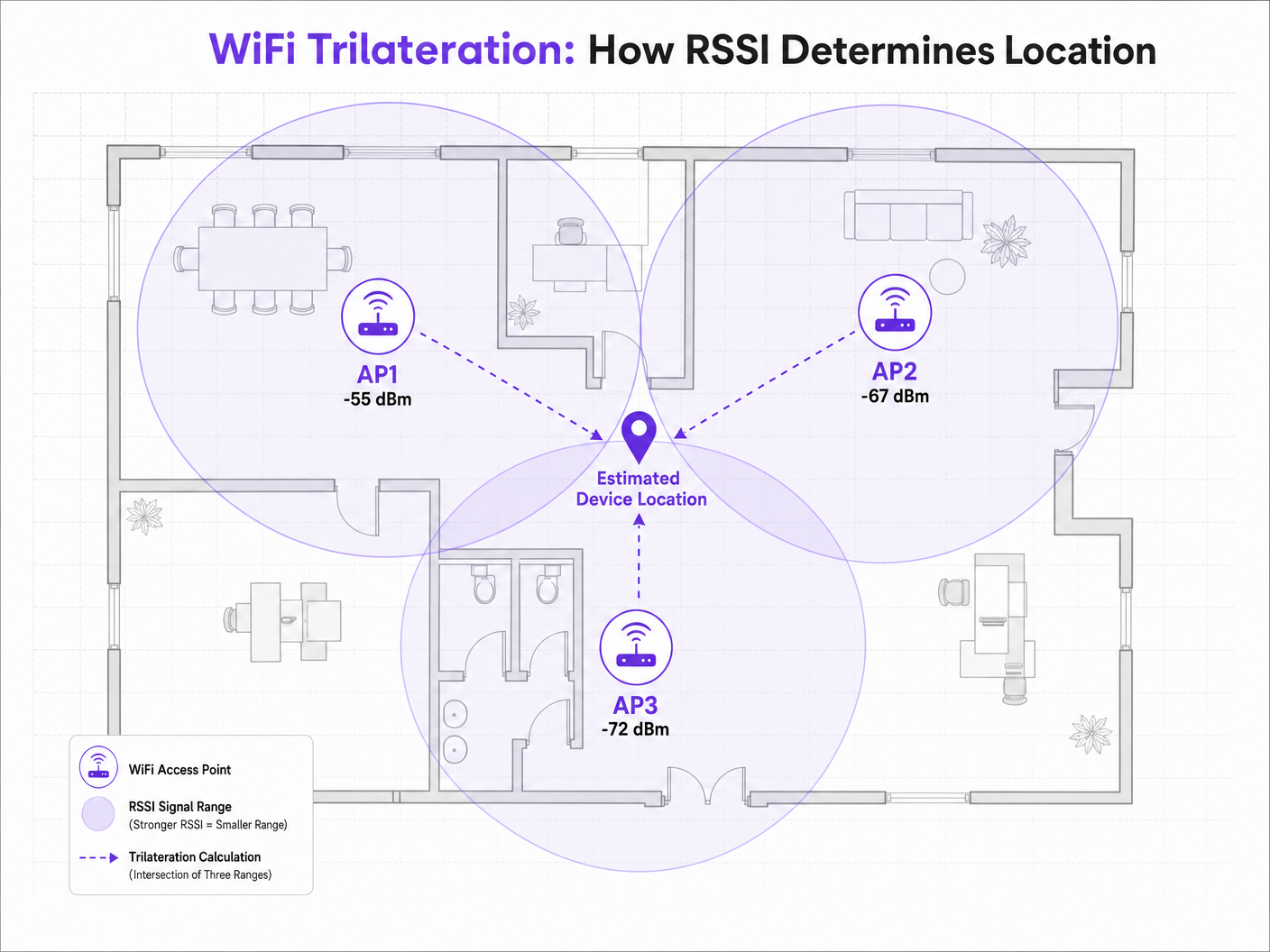
Cuando un dispositivo cliente —como un smartphone que emite solicitudes de sondeo— es detectado por un AP, el AP registra el RSSI. Debido a que las señales de radiofrecuencia (RF) se atenúan (pierden potencia) a medida que viajan por el espacio, el valor de RSSI sirve como un indicador de distancia. Si tres o más AP detectan el mismo dispositivo y registran su RSSI, el motor de posicionamiento puede calcular la distancia estimada desde cada AP, dibujando círculos virtuales de probabilidad. La intersección de estos círculos representa la ubicación estimada del dispositivo.
El Modelo de Pérdida de Trayectoria
La relación entre RSSI y la distancia no es lineal; sigue un modelo logarítmico de pérdida de trayectoria. La fórmula estándar utilizada por los motores de posicionamiento es:
RSSI = -10 * n * log10(d) + A
Donde:
- d es la distancia desde el punto de acceso.
- n es el exponente de pérdida de trayectoria, que representa la rapidez con la que la señal se degrada en el entorno específico. En un vacío de espacio libre, n es exactamente 2.0. En entornos interiores densos, n puede oscilar entre 3.0 y 4.5.
- A es el RSSI de referencia medido exactamente a 1 metro del AP.
Esta fórmula destaca por qué la calibración ambiental es crítica. Una implementación en un entorno de Hospitalidad con paredes de concreto tendrá un exponente de pérdida de trayectoria significativamente diferente al de un piso de Retail abierto. Asumir un valor n estándar en entornos diversos es la principal causa de una precisión deficiente en la orientación.
2.4 GHz vs 5 GHz para Posicionamiento
Aunque la banda de 2.4 GHz ofrece una mejor penetración a través de obstáculos físicos, esta característica es en realidad perjudicial para el posicionamiento de precisión. La mayor huella de propagación significa círculos de estimación de distancia más grandes, lo que resulta en un área de intersección más amplia y una menor resolución posicional.
La banda de 5 GHz se atenúa más rápido, proporcionando límites de señal más ajustados y estimaciones de distancia más granulares. Para una precisión óptima en la orientación, los motores de posicionamiento deben priorizar los datos RSSI de 5 GHz. Este principio también se aplica a los estándares más nuevos; si bien Wi-Fi 6 mejora la eficiencia general de la red, la mecánica fundamental del posicionamiento RSSI sigue siendo la misma, aunque la introducción de la banda de 6 GHz en Wi-Fi 6E ofrece una densidad de canales aún mayor y posibles beneficios de resolución. Para más información, consulte nuestra guía: Wi-Fi 6 vs Wi-Fi 5: ¿Resuelve la Interferencia de Canales? .
Guía de Implementación
Densidad y Ubicación de Puntos de Acceso
El modo de falla más común en las implementaciones de orientación es la densidad insuficiente de AP. Una red diseñada puramente para conectividad (por ejemplo, proporcionar acceso a Guest WiFi ) a menudo carece de la densidad requerida para una trilateración confiable.
Para un posicionamiento confiable, un dispositivo cliente debe ser "escuchado" por un mínimo de tres AP simultáneamente con un RSSI de -75 dBm o mejor.
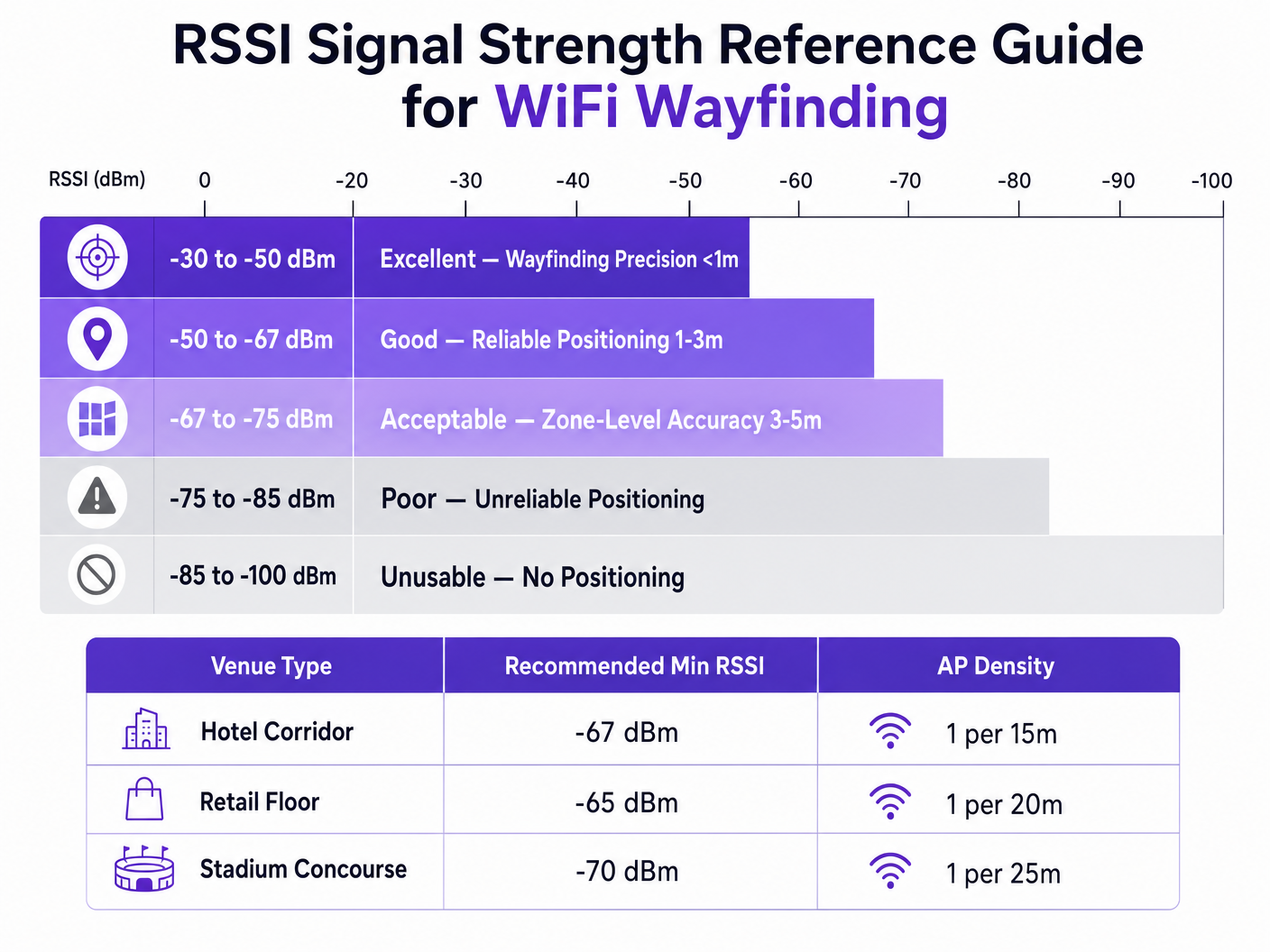
Para lograr una precisión objetivo de 3 a 5 metros, una regla general es implementar un AP por cada 15 a 20 metros cuadrados, dependiendo del entorno. Además, los AP deben colocarse en el perímetro del área objetivo, no solo en el centro de un pasillo, para asegurar que la intersección de los círculos de señal cree un punto definitivo en lugar de una línea recta.
Metodologías de Calibración
Distancia precisala estimación de la ubicación requiere calibrar el motor de posicionamiento al entorno de RF específico. Existen dos enfoques principales:
- Huella de RF: Esto implica recorrer físicamente el lugar con un dispositivo de estudio, registrar los valores de RSSI en coordenadas conocidas y construir una tabla de consulta completa. El motor de posicionamiento luego compara las lecturas de RSSI en tiempo real con esta base de datos. Esto proporciona la mayor precisión, pero requiere mucha mano de obra y debe repetirse si el entorno físico cambia (por ejemplo, exhibiciones minoristas de temporada).
- Posicionamiento Basado en Modelo: Este enfoque utiliza la fórmula de pérdida de trayectoria combinada con parámetros ambientales (tipos de paredes, alturas de techo) definidos en el sistema. Es más rápido de implementar y mantener, y aunque es ligeramente menos preciso que la huella de RF, generalmente es suficiente para análisis a nivel de zona y orientación general.
Mejores Prácticas
Mitigación de la Interferencia por Trayectos Múltiples
En entornos con superficies altamente reflectantes —como escaparates de vidrio, accesorios metálicos o asientos de estadio— las señales de RF rebotan, llegando al receptor a través de múltiples trayectos. Esta interferencia por trayectos múltiples distorsiona la lectura de RSSI, ya que el receptor mide un agregado de las señales directas y reflejadas, en lugar de la distancia limpia de línea de visión.
La mitigación de trayectos múltiples requiere una combinación de ubicación estratégica de AP (evitando esquinas altamente reflectantes), calibración rigurosa y algoritmos de filtrado inteligentes dentro del motor de posicionamiento que puedan descartar picos anómalos de RSSI.
Privacidad y Cumplimiento
Al recopilar datos de ubicación a través de direcciones MAC (incluso pasivamente mediante solicitudes de sondeo), los equipos de TI deben garantizar el cumplimiento de los marcos de privacidad regionales como GDPR.
La implementación de la aleatorización de direcciones MAC por parte de los sistemas operativos móviles modernos evita el seguimiento a largo plazo de dispositivos individuales sin autenticación. Sin embargo, no impide el análisis agregado de afluencia. Para proporcionar orientación individual paso a paso o interacción personalizada, los lugares deben obtener el consentimiento explícito.
Aquí es donde la integración de un Captive Portal se vuelve esencial. Al requerir que los usuarios se autentiquen —quizás aprovechando una solución como How a wi fi assistant Enables Passwordless Access in 2026 — los lugares pueden asociar legalmente un dispositivo con un individuo y proporcionar servicios de ubicación con consentimiento. La plataforma de Purple actúa como un proveedor de identidad gratuito bajo la licencia Connect, simplificando este requisito de cumplimiento mientras ofrece WiFi Analytics enriquecidos.
Solución de Problemas y Mitigación de Riesgos
Cuando la precisión de la orientación se degrada, los equipos de TI deben evaluar sistemáticamente los siguientes vectores:
- Deriva Ambiental: ¿Han ocurrido cambios físicos en el lugar (nuevas paredes, inventario denso) que invalidan la calibración original?
- Niveles de Potencia de AP: ¿Los algoritmos de Gestión de Recursos de Radio (RRM) están ajustando dinámicamente la potencia de transmisión? Los motores de posicionamiento dependen de puntos de referencia estables; los ajustes dinámicos agresivos de potencia distorsionarán los cálculos de distancia.
- Variación del Dispositivo Cliente: Diferentes fabricantes de smartphones utilizan diseños de antena variados, lo que significa que un Samsung y un iPhone en la misma ubicación exacta pueden reportar diferentes valores de RSSI. Los motores de ubicación avanzados utilizan la creación de perfiles de dispositivos para normalizar estas lecturas.
ROI e Impacto Comercial
El caso de negocio para implementar una robusta orientación WiFi va mucho más allá de simplemente mostrar un punto azul en un mapa. Para un Director de Tecnología o Director de Recinto, el ROI se materializa a través de la eficiencia operativa y la toma de decisiones basada en datos.
En un centro de Transport , el posicionamiento preciso permite la gestión dinámica de colas y el envío de personal basado en la densidad de pasajeros en tiempo real. En un entorno de atención médica, facilita el seguimiento de activos para equipos médicos de alto valor, reduciendo el desperdicio en adquisiciones.
Al estandarizar en una plataforma agnóstica de hardware como Purple, las organizaciones pueden extraer esta inteligencia de ubicación sin estar atadas a un único proveedor de infraestructura, asegurando flexibilidad a largo plazo y maximizando el retorno de sus inversiones inalámbricas existentes. Como se destacó en nuestro reciente anuncio, Purple Appoints Iain Fox as VP Growth – Public Sector to Drive Digital Inclusion and Smart City Innovation , la aplicación de esta tecnología se está expandiendo rápidamente a la infraestructura de ciudades inteligentes, demostrando su valor escalable.
Definiciones clave
RSSI (Received Signal Strength Indicator)
A measurement of the power present in a received radio signal, expressed in decibels relative to a milliwatt (dBm).
The fundamental metric used by positioning engines to estimate the distance between a client device and an access point.
Trilateration
The process of determining absolute or relative locations of points by measurement of distances, using the geometry of circles, spheres or triangles.
The mathematical algorithm used by location engines to calculate a device's position based on distance estimates from multiple APs.
Path-Loss Exponent (n)
A variable in the RF propagation model that represents the rate at which signal strength degrades over distance in a specific environment.
Critical for calibration; an open stadium will have a lower path-loss exponent than a dense office environment with concrete walls.
RF Fingerprinting
A calibration technique where a venue is physically surveyed to record actual RSSI values at specific coordinates, creating a lookup database.
Used when high-precision wayfinding is required, though it carries a high operational maintenance cost.
Multipath Interference
A phenomenon in radio physics where RF signals reach the receiving antenna by two or more paths due to reflection off surfaces.
A major source of inaccuracy in wayfinding, particularly in venues with glass, metal, or complex architectural features.
MAC Address Randomisation
A privacy feature in modern mobile OS where the device broadcasts a temporary, randomized MAC address during probe requests.
Impacts the ability to track individual devices over time without network authentication, requiring venues to adapt their analytics strategies.
Probe Request
A frame sent by a client device to determine which access points are within range.
The primary mechanism for passive location tracking, allowing APs to record the RSSI of devices even if they are not connected to the network.
Model-Based Positioning
A location calculation method that relies on mathematical algorithms and environmental assumptions rather than physical site surveys.
The preferred deployment model for scalable, multi-site analytics where zone-level accuracy is sufficient.
Ejemplos resueltos
A 400-room resort hotel is experiencing highly inaccurate wayfinding in its guest corridors, with the 'blue dot' frequently jumping between adjacent floors. The network was originally designed for basic connectivity with APs placed every 30 metres in a straight line down the centre of the hallways.
The IT team must redesign the RF architecture for location services. First, increase AP density to approximately one every 15 metres to ensure a minimum of three APs can 'hear' a client device at -67 dBm or better. Second, stagger the AP placement (e.g., alternating sides of the corridor or utilizing adjacent rooms) rather than a straight line. A straight-line deployment causes the trilateration circles to intersect at two distinct points, creating ambiguity. Finally, implement RF fingerprinting calibration specifically in the corridors to account for the high path-loss exponent caused by fire doors and concrete walls.
A large retail chain wants to deploy zone-level analytics to measure dwell time in specific departments (e.g., Electronics vs. Apparel) using their existing Cisco infrastructure. They want to avoid the operational overhead of manual RF fingerprinting across 50 locations.
Deploy a model-based positioning engine integrated with the existing Cisco wireless LAN controllers via API. The network architect should define the specific environmental parameters (path-loss exponent 'n') for the typical retail floor layout. Ensure that the WLCs are configured to report RSSI data from both associated and unassociated clients (probe requests). Overlay the Purple analytics platform to consume this API feed, mapping the logical AP coordinates to the physical floor plan to establish the analytical zones.
Preguntas de práctica
Q1. You are designing the WiFi infrastructure for a new conference centre. The primary requirement is highly accurate turn-by-turn wayfinding for attendees. The architect proposes placing high-density APs exclusively in the centre of the main exhibition halls to minimize cabling costs. Do you approve this design?
Sugerencia: Consider how trilateration circles intersect when APs are placed in a centralized cluster versus a perimeter deployment.
Ver respuesta modelo
No, this design should be rejected. For accurate trilateration, APs must be placed on the perimeter of the space to provide diverse angles of signal intersection. Centralized AP placement will result in overlapping signal circles that fail to create a definitive intersection point, leading to high positional ambiguity at the edges of the hall.
Q2. Following a recent firmware update to your wireless LAN controllers, the operations team reports that the dwell time analytics in the retail stores have become erratic, with devices appearing to 'teleport' between zones. No physical changes have been made to the stores.
Sugerencia: Consider what automated features a WLC firmware update might enable or alter regarding RF management.
Ver respuesta modelo
Investigate the Radio Resource Management (RRM) or dynamic transmit power control settings on the WLC. Firmware updates often alter the aggressiveness of these algorithms. If the APs are rapidly fluctuating their transmit power to optimize connectivity, the location engine's distance calculations (which rely on a stable reference power) will be entirely skewed, causing the 'teleporting' effect. RRM should be tuned to ensure stable transmit power in location-critical zones.
Q3. A hospital IT director wants to track the location of expensive mobile ultrasound machines. They currently have a legacy WiFi network designed for basic coverage (-75 dBm minimum). They are debating between upgrading the WiFi network for high-density location services or deploying a parallel BLE (Bluetooth Low Energy) beacon network.
Sugerencia: Evaluate the cost and accuracy trade-offs between upgrading a legacy WiFi network versus overlaying a targeted BLE solution for asset tracking.
Ver respuesta modelo
For precise asset tracking (e.g., knowing exactly which room a machine is in), BLE is often the more cost-effective and accurate solution in this scenario. Upgrading a legacy WiFi network to the density required for high-precision wayfinding (1 AP per 15 sqm) requires significant cabling and hardware investment. Deploying battery-powered BLE beacons on the assets and BLE receivers in the rooms provides higher accuracy (due to shorter range and lower power) without disrupting the existing WiFi infrastructure.