Cómo cambiar los canales WiFi para prevenir interferencias
Esta guía técnica exhaustiva ofrece a gerentes de TI, arquitectos de red y directores de operaciones de recintos un enfoque definitivo y paso a paso para identificar fuentes de interferencia WiFi y cambiar estratégicamente los canales WiFi para eliminarlas. Cubre la planificación de bandas de 2.4 GHz y 5 GHz, análisis de espectro, gestión de recursos de radio (Radio Resource Management) y consideraciones de DFS, basándose en los estándares IEEE 802.11 y escenarios de implementación reales. La implementación de estas estrategias proporciona mejoras medibles en el rendimiento de la red, la estabilidad del cliente y el ROI de la infraestructura sin requerir gastos de capital en nuevo hardware.
Escucha esta guía
Ver transcripción del podcast
Resumen Ejecutivo
Para entornos empresariales — desde amplios recintos de Hospitalidad hasta densos espacios de Venta al por menor — un WiFi fiable ya no es un beneficio; es infraestructura crítica. La interferencia sigue siendo la principal culpable de las conexiones caídas, la alta latencia y el bajo rendimiento, impactando directamente tanto la eficiencia operativa como la experiencia del WiFi para Invitados . Esta guía proporciona a arquitectos de red y gerentes de TI un enfoque definitivo y paso a paso para identificar fuentes de interferencia y cambiar estratégicamente los canales WiFi para mitigarlas.
Al implementar las mejores prácticas neutrales al proveedor para la gestión del espectro, las organizaciones pueden maximizar el ROI de su infraestructura, asegurar un roaming de clientes sin interrupciones y soportar la creciente densidad de dispositivos IoT y de usuario sin comprometer la seguridad o los estándares de cumplimiento, incluyendo PCI DSS y GDPR. El principio fundamental es sencillo: la interferencia es un problema de gestión del espectro, no un problema de hardware. La configuración correcta de la infraestructura existente, en la mayoría de los casos, resolverá los problemas de rendimiento que las organizaciones atribuyen erróneamente a una densidad insuficiente de AP o a equipos obsoletos.
Análisis Técnico Detallado
Comprender la capa física de las redes IEEE 802.11 es esencial antes de realizar cualquier cambio de configuración. El espectro de radiofrecuencia (RF) es un medio compartido regido por el protocolo CSMA/CA (Carrier Sense Multiple Access with Collision Avoidance), y la interferencia generalmente se divide en dos categorías distintas: Interferencia Co-Canal (CCI) e Interferencia de Canal Adyacente (ACI).
La Interferencia Co-Canal (CCI) ocurre cuando múltiples puntos de acceso o clientes transmiten en el mismo canal exacto. Aunque los protocolos 802.11 utilizan CSMA/CA para gestionar esto — los dispositivos escuchan antes de transmitir — una CCI excesiva obliga a los dispositivos a esperar por tiempo de aire libre, reduciendo drásticamente el rendimiento y aumentando la latencia. Es fundamentalmente un problema de congestión más que un verdadero ruido de RF, y el mecanismo CSMA/CA puede manejarlo hasta cierto punto con elegancia.
La Interferencia de Canal Adyacente (ACI) es mucho más destructiva. Ocurre cuando los AP operan en frecuencias superpuestas — por ejemplo, los canales 2 y 4 en la banda de 2.4 GHz. Debido a que las transmisiones se superponen pero no pueden ser decodificadas por CSMA/CA, se tratan como ruido puro, elevando el nivel de ruido y causando pérdida de paquetes y retransmisiones. En un recinto concurrido, la ACI puede reducir el rendimiento efectivo entre un 60 y un 70% y es el error de configuración más común encontrado en implementaciones empresariales.
El Dilema de los 2.4 GHz
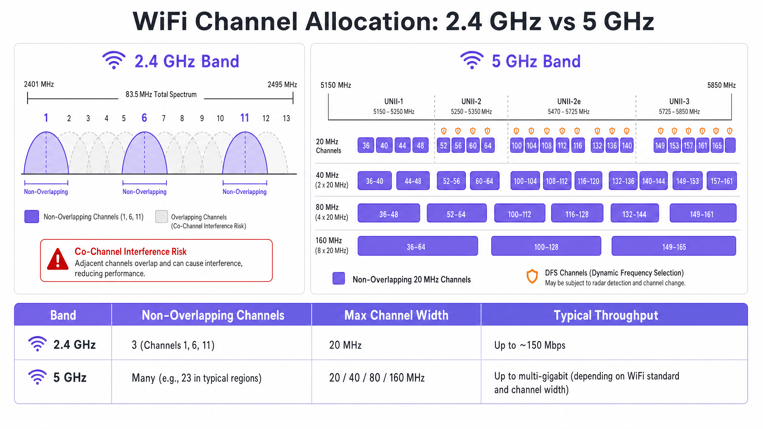
La banda de 2.4 GHz ofrece un mejor alcance y penetración de paredes, pero está severamente limitada por un espectro reducido — aproximadamente 83.5 MHz en total. Aunque hay de 11 a 14 canales dependiendo del dominio regulatorio, solo tres son verdaderamente no superpuestos: Canales 1, 6 y 11. Usar cualquier otro canal en una implementación multi-AP garantiza ACI. Además, esta banda está saturada de interferencias no-WiFi, incluyendo dispositivos Bluetooth, hornos de microondas y teléfonos inalámbricos DECT que operan en el mismo espectro. Para un análisis detallado de cómo Bluetooth Low Energy coexiste con la infraestructura WiFi, consulte nuestra guía sobre BLE Low Energy Explicado para Empresas . Para un tratamiento más amplio de la selección de bandas de frecuencia, consulte Frecuencias Wi Fi: Una Guía de Frecuencias Wi-Fi en 2026 .
La Ventaja de los 5 GHz
La banda de 5 GHz ofrece significativamente más espectro, proporcionando numerosos canales de 20 MHz no superpuestos a través de las sub-bandas UNII-1, UNII-2, UNII-2e y UNII-3. Esta banda es el valor predeterminado correcto para el tráfico de clientes empresariales. Sin embargo, introduce dos complejidades clave: las compensaciones de la agregación de canales y la Selección Dinámica de Frecuencia (DFS).
La agregación de canales — combinando canales de 20 MHz en anchos de 40, 80 o 160 MHz — aumenta el rendimiento máximo de un solo cliente, pero reduce el número total de canales independientes disponibles. En entornos de alta densidad, esto causa una CCI severa. Los canales DFS (principalmente UNII-2 y UNII-2e) requieren que los AP monitoreen las señales de radar y desocupen inmediatamente el canal si se detectan, causando desconexiones de clientes. Esta es una consideración crítica para recintos cercanos a aeropuertos, estaciones meteorológicas o instalaciones militares.
Guía de Implementación
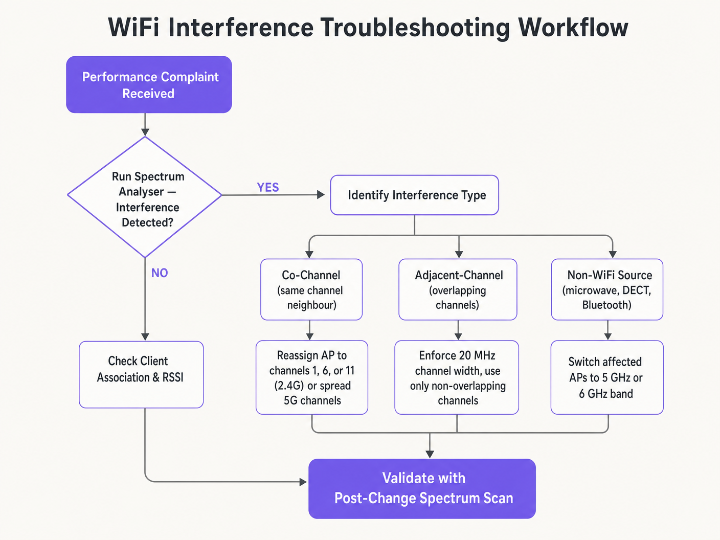
Cambiar los canales WiFi nunca debe basarse en conjeturas. Requiere un enfoque sistemático y basado en datos.
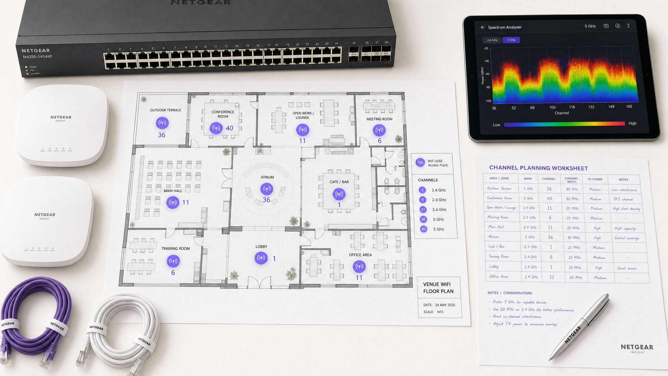
Paso 1: Realizar un Análisis de Espectro
Antes de realizar cualquier cambio de configuración, establezca una línea base empírica. Despliegue un analizador de espectro — ya sea hardware dedicado o las herramientas integradas en su controlador WLAN empresarial — para inspeccionar el entorno de RF en ambas bandas. Documente lo siguiente: APs no autorizados o vecinos y sus asignaciones de canal, el nivel de ruido en cada canal, la presencia de fuentes de interferencia no-WiFi y los niveles actuales de potencia de transmisión de los AP. Esta línea base es su punto de referencia para medir el impacto de los cambios posteriores.
Paso 2: Formular un Plan de Canales
Para la banda de 2.4 GHz: Restrinja el conjunto de canales estrictamente a los canales 1, 6 y 11. Establezca todos los anchos de canal en 20 MHz — esto no es negociable. Si la densidad de AP es lo suficientemente alta como para causar una CCI significativa incluso con el esquema 1-6-11, considere deshabilitar la radio de 2.4 GHz en APs alternos en un patrón de tablero de ajedrez, reduciendo efectivamente a la mitad la densidad de AP de 2.4 GHz mientras mantiene la cobertura a través de los AP restantes.
Para la banda de 5 GHz: Maximice el uso de los canales no superpuestos disponibles. En implementaciones de alta densidad —centros de conferencias, estadios, centros de Transporte — imponga anchos de canal de 20 MHz para maximizar el número de canales independientes. Solo aumente a 40 MHz en áreas de baja densidad donde la CCI no sea una preocupación. Evalúe cuidadosamente la inclusión de canales DFS según su ubicación específica y la proximidad a fuentes de radar. Consulte la lista de disponibilidad de canales de su autoridad reguladora nacional para su región específica.
Paso 3: Configurar Puntos de Acceso
Acceda a su controlador de LAN inalámbrica (WLC) o al panel de control de gestión en la nube para aplicar el plan de canales. La mayoría de las plataformas empresariales ofrecen funciones de Gestión de Recursos de Radio (RRM) o Auto-RF que asignan dinámicamente canales y niveles de potencia.
| Enfoque | Ideal para | Riesgo |
|---|---|---|
| Plan Estático Manual | Lugares complejos, de alta densidad o adyacentes a radares | Requiere una re-inspección periódica a medida que cambia el entorno |
| Auto-RF / RRM | Implementaciones más simples y de menor densidad | Puede causar cambios de canal en entornos de RF volátiles |
| Híbrido | La mayoría de las implementaciones empresariales | Requiere una configuración cuidadosa de las restricciones |
En entornos altamente complejos, un plan de canales estático manual basado en un estudio predictivo suele ofrecer una mayor estabilidad que depender únicamente de Auto-RF. La potencia de transmisión debe ajustarse en paralelo —reduzca la potencia de transmisión del AP a 10–14 dBm en 5 GHz en implementaciones densas para reducir el tamaño de las celdas y la interferencia entre APs.
Paso 4: Validar y Monitorear
Después de aplicar los cambios, realice un estudio de recorrido posterior a la implementación para validar el nuevo plan de canales. Monitoree los indicadores clave de rendimiento (KPIs) a través de su plataforma de Análisis de WiFi , centrándose en las tasas de reintento, la utilización del tiempo de aire por AP, el recuento de asociaciones de clientes y el comportamiento de roaming. Un entorno de RF bien ajustado debería mostrar tasas de reintento inferiores al 10% y una utilización del tiempo de aire inferior al 70% durante los períodos pico.
Mejores Prácticas
Imponga anchos de 20 MHz en alta densidad. En entornos como centros de conferencias o estadios, priorice la capacidad —más canales no superpuestos— sobre el rendimiento máximo de un solo cliente de canales más anchos. El rendimiento agregado de la red será significativamente mayor.
Implemente la dirección de banda de forma agresiva. Configure la dirección de banda para alejar a los clientes compatibles con 5 GHz de la banda congestionada de 2.4 GHz. La mayoría de los controladores empresariales modernos lo soportan de forma nativa. Reserve 2.4 GHz para dispositivos IoT y hardware heredado que no puede operar en 5 GHz.
Deshabilite las tasas de datos heredadas. Deshabilite las tasas de datos 802.11b (1, 2, 5.5, 11 Mbps) en todos los SSIDs. Estas tasas heredadas consumen un tiempo de aire desproporcionado y ralentizan toda la red. Establecer una tasa de datos mínima de 12 o 24 Mbps obliga a los clientes a hacer roaming antes y reduce la sobrecarga de los marcos de gestión.
Programe auditorías de RF regulares. El entorno de RF es dinámico. Nuevas redes vecinas, modificaciones de edificios y nuevos equipos cambian el panorama de interferencias. Programe auditorías de RF trimestrales para mantener su plan de canales actualizado.
Integre la seguridad y la gestión de red. Asegúrese de que la detección y mitigación de APs no autorizados estén habilitadas para evitar que dispositivos no autorizados causen interferencias o brechas de seguridad. Para un contexto de seguridad de red más amplio, incluido el filtrado de contenido en redes de invitados, revise ¿Qué es el filtrado DNS? Cómo bloquear contenido dañino en el WiFi de invitados . Para estrategias de optimización específicas de oficina, consulte Wi-Fi de Oficina: Optimice su Red Wi-Fi Moderna de Oficina .
Solución de Problemas y Mitigación de Riesgos
Síntoma: Señal fuerte, bajo rendimiento. Esta es la característica distintiva de la Interferencia Co-Canal. El piso de ruido es bajo pero el tiempo de aire está saturado. Audite las asignaciones de canales y la potencia de transmisión del AP. Reduzca la potencia de TX e imponga anchos de canal de 20 MHz para liberar tiempo de aire y mejorar la reutilización espacial.
Síntoma: Desconexiones aleatorias de clientes en zonas específicas. Revise los registros de eventos DFS inmediatamente. Si los APs en esa zona están en canales UNII-2 o UNII-2e y están cerca de una fuente de radar, se les exigirá legalmente que desocupen el canal, desconectando a los clientes. Excluya esos canales DFS específicos del plan de canales para las zonas afectadas.
Síntoma: El plan de canales cambia automáticamente. Esto es un cambio de canal causado por un algoritmo Auto-RF excesivamente sensible que reacciona a interferencias transitorias. Restrinja la configuración de sensibilidad de RRM, aumente el temporizador de retención o migre a un plan de canales estático basado en datos de estudio.
Síntoma: Bajo rendimiento en áreas específicas a pesar de una buena señal. La interferencia no-WiFi de hornos de microondas, teléfonos DECT o equipos industriales puede estar elevando el piso de ruido. Un analizador de espectro identificará estas fuentes. La solución es eliminar la fuente o migrar los APs afectados a la banda de 5 GHz o 6 GHz, que es inmune a la mayoría de los interferentes no-WiFi de 2.4 GHz.
ROI e Impacto Comercial
Optimizar los canales WiFi es una mejora de infraestructura de costo cero que produce retornos inmediatos y medibles. Las organizaciones que implementan una planificación adecuada de canales de RF suelen reportar una reducción del 30–40% en los tickets de soporte relacionados con WiFi dentro del primer trimestre. En entornos de Salud , un entorno de RF correctamente ajustado garantiza un flujo ininterrumpido de datos de telemetría críticos y apoya el cumplimiento de los requisitos de comunicación de dispositivos clínicos. En Comercio Minorista , garantiza el funcionamiento sin interrupciones de los sistemas de punto de venta móviles, análisis de ubicación precisos y aplicaciones confiables de gestión de inventario.
Desde la perspectiva del gasto de capital, una planificación correcta de los canales elimina con frecuencia la necesidad percibida de hardware AP adicional. Muchas organizaciones que creen tener una densidad de APproblema de calidad en realidad tienen un problema de planificación de canales. Resolver la configuración de RF primero —antes de adquirir hardware adicional— es una práctica estándar en cualquier evaluación de red rigurosa. Un entorno de RF correctamente ajustado también extiende el ciclo de vida operativo de la infraestructura existente, aplazando costosos ciclos de actualización de hardware y entregando un retorno directo y cuantificable sobre la inversión de capital existente.
Definiciones clave
Co-Channel Interference (CCI)
Interference that occurs when multiple access points or client devices transmit on the exact same frequency channel simultaneously.
Managed by CSMA/CA, but causes congestion and reduced throughput when excessive. The primary symptom is high airtime utilisation with low throughput.
Adjacent-Channel Interference (ACI)
Interference caused by devices transmitting on overlapping but non-identical frequency channels, creating RF noise that CSMA/CA cannot decode or manage.
More destructive than CCI. Raises the noise floor, causes packet loss, and forces retransmissions. Caused by using channels other than 1, 6, and 11 on 2.4 GHz.
Dynamic Frequency Selection (DFS)
An IEEE 802.11h mechanism that requires WiFi access points to monitor for radar signals on certain 5 GHz channels and immediately vacate the channel if radar is detected.
Affects UNII-2 and UNII-2e channels. Critical consideration for venues near airports, weather stations, or military sites, where frequent radar detection causes client disconnections.
Radio Resource Management (RRM)
Automated algorithms within enterprise WLAN controllers that dynamically adjust channel assignments and transmit power levels based on real-time RF conditions.
Useful for adapting to changing RF environments, but can cause 'channel churn' — frequent channel changes — in volatile environments, disrupting client connectivity.
Channel Bonding
The process of combining multiple adjacent 20 MHz channels into wider 40, 80, or 160 MHz channels to increase peak single-client throughput.
Reduces the total number of available non-overlapping channels, increasing CCI risk in dense deployments. Should be avoided in high-density enterprise environments.
Band Steering
A WLAN controller feature that encourages dual-band capable client devices to associate with the 5 GHz band rather than the congested 2.4 GHz band.
Essential for load balancing in enterprise deployments. Preserves the limited 2.4 GHz spectrum for IoT devices and legacy hardware that cannot operate on 5 GHz.
CSMA/CA
Carrier Sense Multiple Access with Collision Avoidance. The medium access control protocol used by IEEE 802.11 WiFi, requiring devices to listen for clear airtime before transmitting.
The mechanism that governs how WiFi devices share the RF medium. High CCI forces devices to wait longer for clear airtime, directly reducing throughput and increasing latency.
Noise Floor
The aggregate level of background RF energy present in a given frequency band, measured in dBm. A higher noise floor reduces the effective Signal-to-Noise Ratio (SNR) for WiFi transmissions.
Raised by ACI, non-WiFi interference, and poor channel planning. A high noise floor forces devices to use lower modulation schemes and data rates, reducing throughput.
Spatial Reuse
The ability of multiple access points to simultaneously transmit on the same channel without interfering with each other, enabled by physical separation and appropriate transmit power levels.
The fundamental mechanism that allows high-density WiFi networks to scale. Maximised by reducing AP transmit power and using the minimum necessary channel widths.
Ejemplos resueltos
A 200-room hotel is experiencing widespread complaints of slow WiFi during the evening peak. The current deployment uses 40 MHz channels on the 2.4 GHz band across 80 APs, and Auto-RF is enabled. The WLAN controller logs show frequent channel changes throughout the evening.
Phase 1 — Immediate remediation: Reconfigure all 2.4 GHz radios to 20 MHz channel widths immediately. Restrict the 2.4 GHz channel pool to channels 1, 6, and 11 only within the controller. This alone will eliminate ACI across the deployment.
Phase 2 — Stabilise Auto-RF: Review the Auto-RF event logs. If APs are changing channels more than once per hour, the algorithm is reacting to transient interference. Increase the RRM hold-down timer and reduce the sensitivity threshold. If churn persists, migrate to a static channel plan.
Phase 3 — Band steering: Enable aggressive band steering to push dual-band devices to 5 GHz. This reduces 2.4 GHz load significantly during peak periods.
Phase 4 — Validation: Deploy a spectrum analyser post-change and monitor retry rates and airtime utilisation via the WiFi analytics dashboard for 48 hours to confirm improvement.
A large retail chain has deployed APs every 12 metres across a 4,000 sq metre distribution centre. Even on the 5 GHz band using 20 MHz channels, CCI is high, throughput is poor, and mobile scanning devices are experiencing frequent disconnections during peak shift hours.
Step 1 — Audit transmit power: The APs are almost certainly configured at maximum TX power (typically 20–23 dBm). At 12-metre spacing, this creates massive cell overlap. Reduce TX power to 10–12 dBm on 5 GHz to shrink cell sizes and reduce inter-AP interference.
Step 2 — Disable legacy data rates: Disable all 802.11b/g data rates below 12 Mbps. This forces scanning devices to roam to the nearest AP rather than staying associated with a distant AP at a low data rate, which consumes disproportionate airtime.
Step 3 — Review channel plan: Ensure the 5 GHz channel plan uses the maximum number of non-overlapping channels available. With high AP density, every unique channel matters.
Step 4 — Validate with post-change survey: Conduct a walkthrough survey with a spectrum analyser to confirm reduced inter-AP overlap and improved SNR across the floor.
Preguntas de práctica
Q1. You are deploying a new wireless network in a multi-tenant office building. Your spectrum scan shows heavy utilisation on channels 1, 6, and 11 from neighbouring tenants. A junior engineer suggests using channels 3, 8, and 13 to 'avoid the congestion'. How do you respond, and what is the correct configuration?
Sugerencia: Consider the difference between Co-Channel Interference (CCI) and Adjacent-Channel Interference (ACI), and which is more harmful to network performance.
Ver respuesta modelo
The junior engineer's suggestion is incorrect and would cause severe performance degradation. Channels 3, 8, and 13 overlap with channels 1, 6, and 11 respectively, which would introduce Adjacent-Channel Interference — the most destructive form of WiFi interference. ACI manifests as pure RF noise that CSMA/CA cannot manage, causing packet loss and retransmissions. The correct configuration is to deploy on channels 1, 6, and 11. While this will cause Co-Channel Interference with the neighbouring tenants, CSMA/CA can handle CCI gracefully by having devices take turns. The aggregate performance will be significantly better than with ACI.
Q2. A stadium deployment is using 80 MHz channels on the 5 GHz band to advertise 'Gigabit WiFi' speeds during events. Users report slow loading times, frequent disconnections, and poor video streaming quality during peak occupancy. The AP hardware is modern WiFi 6 equipment. What is the architectural flaw, and what is the remediation?
Sugerencia: Evaluate the trade-off between peak single-client throughput and overall network capacity in a high-density environment.
Ver respuesta modelo
The architectural flaw is the use of 80 MHz channel widths in a high-density environment. Each 80 MHz channel bonds four 20 MHz channels together, drastically reducing the total number of non-overlapping channels available across the deployment. With many APs forced to reuse the same wide channels, Co-Channel Interference becomes severe. The solution is to reduce channel widths to 20 MHz across all APs. This increases the number of independent channels available, reduces CCI, and significantly improves aggregate network capacity. The peak throughput per client will decrease, but the number of clients that can be served simultaneously — and the quality of their experience — will increase substantially.
Q3. Your hospital network experiences intermittent client disconnections affecting medical devices in wards near the hospital's rooftop helipad. The affected APs are configured to use channels 52, 56, 60, and 64. What is the most likely cause, and what is the correct remediation?
Sugerencia: Consider the regulatory requirements for the specific 5 GHz channels in use and what systems operate near a helipad.
Ver respuesta modelo
Channels 52, 56, 60, and 64 are UNII-2 DFS channels. The helicopters using the helipad, or associated aviation radar systems, are likely triggering DFS radar detection events on the APs in that zone. When radar is detected, the APs are legally required to immediately vacate those channels, causing client disconnections. The correct remediation is to exclude all DFS channels from the channel plan for APs in the zones near the helipad. Reconfigure those APs to use UNII-1 channels (36, 40, 44, 48) or UNII-3 channels (149, 153, 157, 161, 165), which are not subject to DFS requirements.