Comprendiendo los algoritmos de selección de BSSID y canales
Esta guía de referencia técnica autorizada desmitifica la arquitectura BSSID y los algoritmos de selección dinámica de canales para implementaciones inalámbricas empresariales. Proporciona estrategias de implementación accionables para arquitectos de TI y equipos de operaciones de recintos para eliminar clientes "pegajosos", mitigar la interferencia de co-canal y construir una base de RF resiliente. Un plan estable de BSSID y canales es también un requisito previo directo para análisis de ubicación precisos e inteligencia de negocios a través de plataformas como Purple.
Escucha esta guía
Ver transcripción del podcast
Resumen Ejecutivo
Para los líderes de TI empresariales que gestionan entornos complejos —desde estadios de alta densidad hasta extensos campus hospitalarios— la cobertura inalámbrica bruta ya no es el desafío principal. Los puntos críticos de falla en las implementaciones inalámbricas modernas ocurren en el límite de roaming, impulsados por una gestión deficiente de la transición de BSSID y una asignación subóptima de canales.
Esta guía de referencia técnica proporciona un análisis profundo y neutral del proveedor sobre la mecánica del Basic Service Set Identifier (BSSID) y los algoritmos de selección dinámica de canales. Al comprender cómo los dispositivos cliente interpretan los BSSID y cómo los controladores empresariales gestionan el espectro de RF, los arquitectos de TI pueden eliminar los "clientes pegajosos", mitigar la interferencia de co-canal y asegurar un roaming sin interrupciones en cualquier escala de recinto. Además, una base de RF estable es un requisito previo directo para extraer datos de ubicación precisos a través de WiFi Analytics , impactando directamente la inteligencia de negocios y el ROI. Ya sea que opere una cadena hotelera, una propiedad minorista o una instalación del sector público, los principios de esta guía se aplican universalmente.
Análisis Técnico Detallado
La distinción entre BSSID y SSID
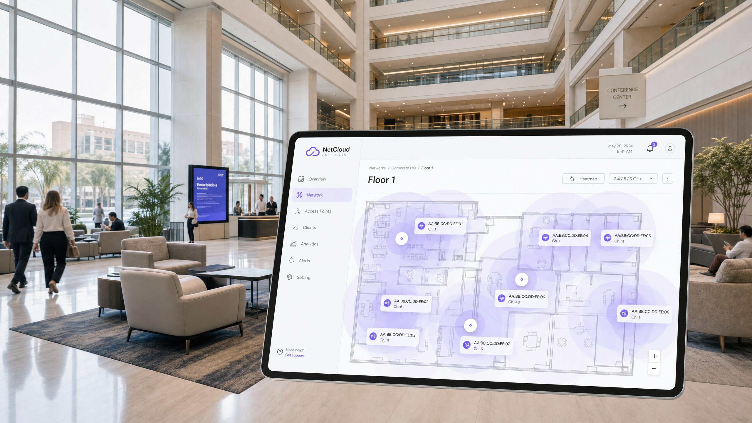
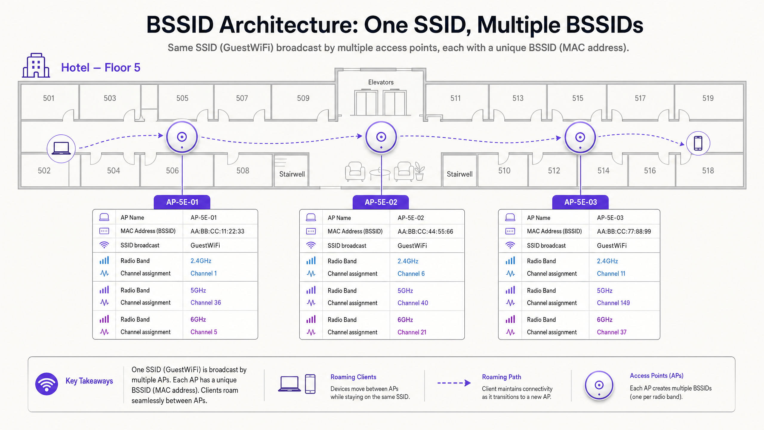
Cuando un usuario se conecta a su red Guest WiFi , ve el SSID —el Service Set Identifier. Esta es la etiqueta legible por humanos transmitida por la red, como "Hotel_Guest" o "RetailWiFi". El SSID es puramente un identificador lógico. La asociación 802.11 real ocurre en la capa física con el BSSID.
El BSSID (Basic Service Set Identifier) es la dirección MAC de la interfaz de radio específica en un punto de acceso que transmite ese SSID. En un entorno multi-AP, un solo SSID es transmitido por docenas o cientos de BSSID únicos. Un punto de acceso de doble radio que transmite un SSID presentará dos BSSID distintos —uno por banda de radio. Un punto de acceso Wi-Fi 6E de triple radio presentará tres.
Esta distinción tiene implicaciones operativas significativas. Cuando se soluciona un problema de roaming, no se investiga el SSID, sino la transición de BSSID. Las herramientas de diagnóstico del lado del cliente, como wpa_cli en Linux o la utilidad Wireless Diagnostics de macOS, expondrán el BSSID específico (dirección MAC) al que está asociado un dispositivo, el canal y el RSSI.
El mecanismo de Roaming: ¿Quién tiene realmente el control?
Este es el aspecto más incomprendido de la arquitectura inalámbrica empresarial. El estándar 802.11 sitúa la decisión de roaming completamente en el dispositivo cliente. La infraestructura de red no puede forzar a un cliente a hacer roaming. Solo puede influir en las condiciones que hacen que el roaming sea más o menos probable.
Un dispositivo cliente evalúa el Received Signal Strength Indicator (RSSI) y el Signal-to-Noise Ratio (SNR) de su BSSID actual frente a los BSSID vecinos. Cuando el BSSID actual se degrada por debajo de un umbral específico del dispositivo —típicamente alrededor de -70 dBm para dispositivos Apple iOS y -75 dBm para muchos dispositivos Android— el cliente inicia un escaneo para un BSSID mejor transmitiendo Probe Requests. Los puntos de acceso cercanos responden con Probe Responses. El cliente evalúa estas respuestas e inicia una autenticación y reasociación 802.11 al BSSID seleccionado.
Si la planificación de canales es deficiente, el cliente puede experimentar interferencia de canal adyacente, corrompiendo los marcos de baliza de los BSSID vecinos. Esto lleva al fenómeno del "cliente pegajoso" —un dispositivo se aferra a un BSSID débil y distante porque no puede escuchar claramente la alternativa más fuerte y cercana. El resultado es un rendimiento degradado, llamadas VoIP caídas y sesiones de aplicación fallidas.
Selección de Canales: La Base de la Arquitectura de RF
La Restricción de 2.4 GHz
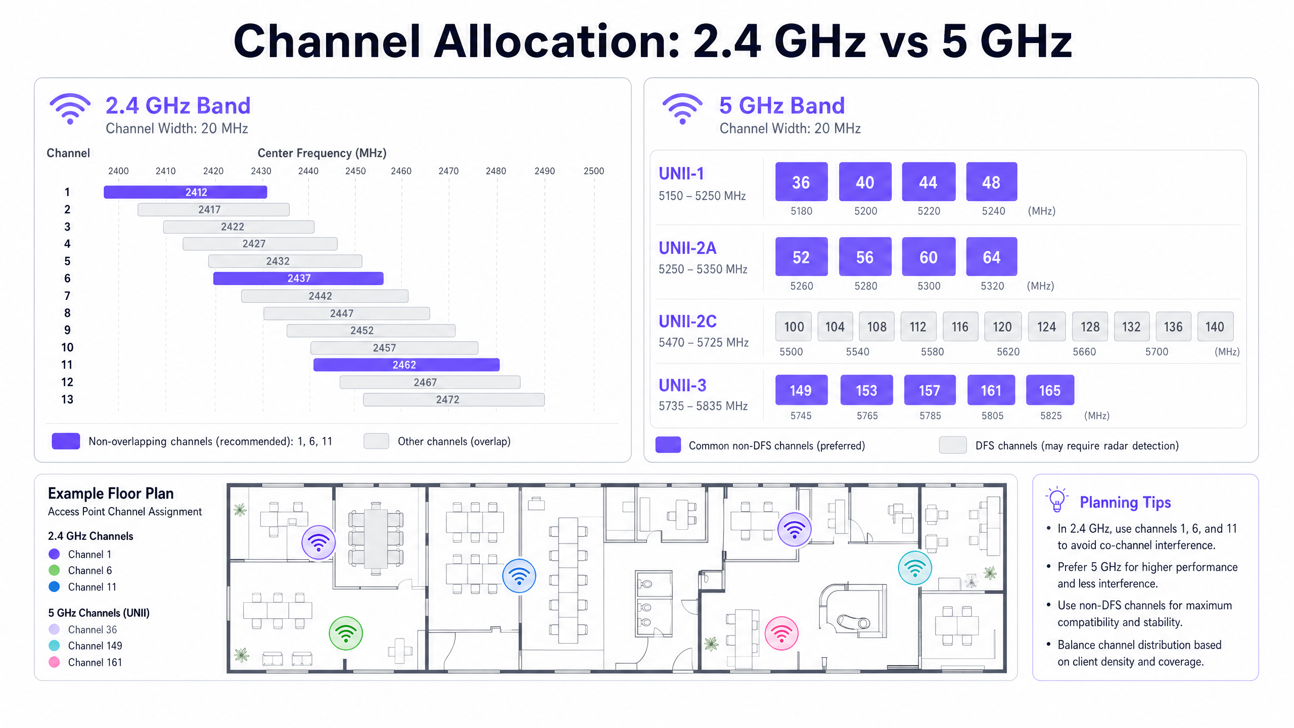
La banda de 2.4 GHz abarca 83.5 MHz de espectro, desde 2.400 GHz hasta 2.4835 GHz. Cada canal 802.11 tiene un ancho de 20 MHz. Con un espaciado de 5 MHz entre las frecuencias centrales de los canales, el resultado es una superposición significativa entre canales adyacentes. Solo los canales 1, 6 y 11 no se superponen en la banda de 2.4 GHz.
El uso de cualquier canal que no sea 1, 6 u 11 en la banda de 2.4 GHz crea Interferencia de Canal Adyacente (ACI). La ACI es categóricamente peor que la Interferencia de Co-Canal (CCI) porque corrompe completamente los paquetes de datos, requiriendo retransmisiones. La CCI, por el contrario, obliga a los dispositivos a compartir el tiempo de aire de forma cooperativa a través de CSMA/CA, lo que degrada el rendimiento pero no corrompe los paquetes. La regla es absoluta: las implementaciones de 2.4 GHz deben usar solo los canales 1, 6 y 11.
Para una comprensión más amplia de cómo interactúan las bandas de frecuencia en entornos empresariales modernos, consulte nuestra guía sobre Frecuencias Wi-Fi: Una guía de frecuencias Wi-Fi en 2026 .
La Oportunidad de 5 GHz y la Complejidad de DFS
La banda de 5 GHz ofrece considerablemente más espectro. En el dominio regulatorio del Reino Unido y la UE, hay hasta 19 canales de 20 MHz no superpuestos disponibles en UNII-1 (5.150–5.250 GHz), UNII-2A (5.250–5.350 GHz), UNII-2C (5.470–5.725 GHz) y UNII-3 (5.735–5.835 GHz).
Sin embargo, los canales UNII-2A y UNII-2C caen dentro del rango DFS (Dynamic Frequency Selection). Estos canales se comparten con radares meteorológicos, radares militares y sistemas de control de tráfico aéreo. Si un punto de acceso detecta un pulso de radar en un canal DFS, debe desocupar inmediatamente el canal y permanecer en silencio en él durante 30 minutos. Este es un mandato regulatorio bajo ETSI EN 301 893 en Europa y FCC Parte 15 en los Estados Unidos.
Para recintos cerca de aeropuertos, miinstalaciones militares o estaciones meteorológicas —comunes en implementaciones de Hospitalidad y Transporte —, los eventos DFS pueden ocurrir varias veces al día, causando cambios impredecibles en el canal del AP y desconexiones de clientes.
Asignación Dinámica de Canales (DCA)
Los controladores de LAN inalámbrica empresariales modernos abordan la gestión de canales mediante algoritmos de Asignación Dinámica de Canales (DCA). Estos algoritmos evalúan continuamente:
| Métrica | Descripción | Impacto |
|---|---|---|
| Utilización del Canal | Porcentaje de tiempo que el medio está ocupado | La alta utilización activa la consideración de cambio de canal |
| Nivel de Ruido | Interferencia de RF no 802.11 (Bluetooth, microondas, etc.) | El nivel de ruido elevado reduce la SNR efectiva |
| RSSI del AP Vecino | Intensidad de la señal de los AP de canal compartido y adyacentes | La alta superposición activa el reequilibrio del canal |
| Eventos DFS | Detección de radar en el canal actual | Cambio de canal inmediato obligatorio |
Si bien el DCA es esencial para mantener un entorno de RF saludable, las configuraciones de algoritmos excesivamente agresivas causan inestabilidad en la red. Cada vez que un AP cambia de canal, todos los clientes conectados se desconectan temporalmente y deben volver a asociarse. En un centro de conferencias durante una presentación magistral, o en el piso de ventas de un comercio minorista durante las horas pico, esto es inaceptable desde el punto de vista operativo.
El enfoque recomendado es configurar el DCA para que se ejecute de forma programada —típicamente durante las ventanas de mantenimiento nocturnas— con un umbral de interferencia del 30% o superior para los cambios no programados. Los eventos obligatorios de evasión de radar DFS son la única excepción a esta disciplina de programación.
Guía de Implementación
Los siguientes pasos de implementación neutrales al proveedor se aplican a implementaciones empresariales en entornos de Hospitalidad , Comercio Minorista , Atención Médica y del sector público.
Paso 1 — Deshabilitar Tasas de Datos Heredadas. Elimine las tasas de datos 802.11b (1, 2, 5.5 y 11 Mbps) de todos los perfiles de radio de los puntos de acceso. Estas tasas heredadas consumen un tiempo de aire desproporcionado y son el principal impulsor del comportamiento de "cliente pegajoso". Cuando se deshabilitan, la tasa de conexión mínima viable aumenta, forzando a los clientes a alcanzar su umbral de roaming en la ubicación física correcta.
Paso 2 — Reducir la Potencia de Transmisión del AP. Ejecutar los AP con la máxima potencia de transmisión (20 dBm) crea celdas de tamaño excesivo e impide un roaming BSSID adecuado. Reduzca la potencia de transmisión de 2.4 GHz a 8–12 dBm y la potencia de transmisión de 5 GHz a 12–17 dBm, calibrada para coincidir con la potencia de transmisión del dispositivo cliente más débil en su entorno.
Paso 3 — Restringir Anchos de Canal. En entornos de alta densidad, restrinja los canales de 5 GHz a 20 MHz. Si bien la unión de canales de 40 MHz y 80 MHz aumenta el rendimiento teórico de un solo dispositivo, reduce los canales no superpuestos disponibles y eleva el nivel de ruido, causando una CCI severa en implementaciones densas.
Paso 4 — Configurar Ventanas de Mantenimiento de DCA. Configure el algoritmo DCA de su controlador para que se ejecute durante las ventanas de mantenimiento nocturnas. Configure un umbral de interferencia del 30% para los disparadores no programados. Esto evita cambios de canal disruptivos durante las horas operativas mientras se mantiene la higiene de RF.
Paso 5 — Planificar la Estrategia de Retorno de DFS. Para lugares con proximidad de radar conocida, excluya los canales DFS del grupo DCA para los AP de misión crítica. Confíe en los canales no DFS UNII-1 (36, 40, 44, 48) y UNII-3 (149, 153, 157, 161, 165) como plan de canal principal. Para obtener orientación sobre la modernización más amplia del control de acceso a la red, consulte La lista de verificación para migrar de NAC heredado a NAC nativo de la nube .
Paso 6 — Habilitar Band Steering. Configure el band steering para dirigir a los clientes con capacidad de doble banda a la banda de 5 GHz, liberando el espectro de 2.4 GHz para dispositivos heredados y equipos IoT. Para obtener contexto sobre la coexistencia de IoT y BLE en entornos empresariales, consulte BLE Low Energy Explained for Enterprise .
Mejores Prácticas
Las siguientes mejores prácticas se alinean con los estándares IEEE 802.11, los requisitos de certificación de Wi-Fi Alliance y las directrices de implementación empresarial neutrales al proveedor.
Umbrales Mínimos de RSSI: Configure los puntos de acceso para rechazar la asociación de clientes con un RSSI inferior a -80 dBm. Esto evita que los clientes débiles se asocien con un AP distante y consuman tiempo de aire a bajas tasas de datos. La mayoría de los controladores empresariales exponen esto como un umbral de "RSSI mínimo" o "exclusión de cliente".
Transición Rápida de BSS 802.11r: Habilite 802.11r (Transición Rápida de BSS) en todos los SSIDs que admitan aplicaciones de voz o en tiempo real. Esto reduce el tiempo de transferencia de roaming de 50–200 ms (re-asociación estándar) a menos de 50 ms, evitando caídas de llamadas VoIP durante las transiciones de BSSID.
Reporte de Vecinos 802.11k y 802.11v: Habilite 802.11k (Gestión de Recursos de Radio) y 802.11v (Gestión de Transición de BSS) para proporcionar a los clientes listas de AP vecinos y recomendaciones de transición. Si bien el cliente aún toma la decisión final de roaming, estos protocolos le proporcionan la información necesaria para tomar una decisión más rápida e informada.
WPA3 y OWE: Para redes de invitados, implemente WPA3-SAE o Cifrado Inalámbrico Oportunista (OWE) para proporcionar cifrado por sesión sin requerir una contraseña. Esto se alinea con las obligaciones de protección de datos GDPR para los datos de invitados en tránsito y es un requisito de PCI DSS para cualquier segmento de red que maneje datos de titulares de tarjetas.
Auditorías de RF Regulares: Realice un estudio de RF pasivo cada 12 meses o después de cualquier cambio físico significativo en el lugar (nuevas particiones, instalaciones de equipos, reordenamientos de muebles). Los cambios físicos alteran la propagación de RF y pueden invalidar su plan de canales.
Solución de Problemas y Mitigación de Riesgos
La Trampa DFS
En implementaciones de hospitalidad cerca de aeropuertos o estaciones meteorológicas, los eventos DFS son un riesgo común y subestimado. Cuando un AP detecta radar en un canal DFS, debe desocuparlo inmediatamente. Si el canal de respaldosi el canal está asignado estáticamente a una frecuencia ya congestionada, el AP causará una cascada de CCI en los AP adyacentes.
Mitigación: Mantenga una lista dinámica de canales de respaldo seguros dentro de su configuración DCA. Considere excluir los canales DFS por completo en los AP que dan servicio a áreas de misión crítica, como vestíbulos de hoteles, escenarios de conferencias o zonas de puntos de venta minoristas.
La trampa de alta potencia
Contrariamente a la intuición, ejecutar los AP a la máxima potencia de transmisión es una de las causas más comunes del bajo rendimiento inalámbrico. Los AP de alta potencia crean celdas grandes con una superposición significativa, lo que provoca CCI y evita que los clientes se conecten al AP más cercano.
Mitigación: Implemente el Control de Potencia de Transmisión (TPC) y calibre la potencia del AP para crear celdas que se superpongan aproximadamente entre un 15 y un 20% en la línea de contorno de -67 dBm. Esto proporciona una cobertura perfecta sin interferencias excesivas.
La trampa del canal ancho
En entornos densos, los proveedores suelen recomendar configuraciones de canal de 80 MHz o 160 MHz para maximizar los puntos de referencia de rendimiento. En la práctica, reducen el número de canales no superpuestos disponibles a 2-3 en la banda de 5 GHz, lo que garantiza una CCI grave en cualquier implementación con más de un puñado de AP.
Mitigación: Restrinja los anchos de canal a 20 MHz en entornos de alta densidad. Reserve configuraciones de 40 MHz u 80 MHz para áreas de baja densidad con una separación física significativa entre los AP.
ROI e impacto empresarial
Un entorno de RF meticulosamente planificado tiene un impacto directo y medible en los resultados empresariales en todo tipo de recintos.
Satisfacción del huésped e ingresos: En entornos de hostelería, la calidad del WiFi se clasifica constantemente entre los tres factores principales en las encuestas de satisfacción del huésped. El roaming BSSID sin interrupciones evita las videollamadas caídas, los tiempos de espera de las aplicaciones y las interrupciones de la transmisión. Para los operadores de hoteles, esto afecta directamente las puntuaciones de las reseñas y las tasas de reserva repetidas.
Precisión de los análisis: La plataforma WiFi Analytics de Purple se basa en asociaciones BSSID de clientes consistentes para generar recuentos precisos de afluencia, métricas de tiempo de permanencia y mapas de calor a nivel de zona. Si los clientes pierden constantemente las conexiones debido a la interferencia del canal, los datos de asociación subyacentes se fragmentan y no son fiables. Un entorno de RF estable no es solo un requisito de rendimiento, es un requisito de calidad de los datos.
Eficiencia operativa: Un plan de canales y una configuración de roaming bien ajustados reducen significativamente el volumen de tickets de soporte relacionados con "WiFi lento" o "se desconecta constantemente". En implementaciones de grandes recintos, esto puede representar una reducción medible en los costos de soporte de nivel 1. Para obtener orientación sobre la optimización de implementaciones a escala de oficina, consulte Office Wi Fi: Optimize Your Modern Office Wi-Fi Network .
Postura de cumplimiento: La gestión adecuada de los canales y los estándares de cifrado (WPA3, 802.1X) respaldan directamente el cumplimiento de PCI DSS para operadores minoristas y de hostelería, y el cumplimiento de GDPR para cualquier organización que procese datos personales a través de WiFi para invitados. Un registro de auditoría de RF documentado también respalda los requisitos de certificación ISO 27001.
Escuche el podcast informativo para ejecutivos anterior para una explicación de 10 minutos, al estilo de un consultor, sobre la arquitectura BSSID y la estrategia de selección de canales.
Definiciones clave
BSSID (Basic Service Set Identifier)
The MAC address of the specific radio interface on an access point broadcasting an SSID. In a multi-AP deployment, each radio presents a unique BSSID, even when all APs broadcast the same SSID.
IT teams encounter BSSIDs when troubleshooting roaming failures, analysing client association logs, or interpreting WiFi analytics data. A client's BSSID association history reveals its physical movement path through a venue.
SSID (Service Set Identifier)
The human-readable network name broadcasted to end users (e.g., 'Purple_Guest'). A single SSID is typically supported by hundreds of underlying BSSIDs in an enterprise deployment.
Users interact with SSIDs; network engineers troubleshoot BSSIDs. Conflating the two is the most common source of roaming misdiagnosis.
Co-Channel Interference (CCI)
Interference caused when two or more access points operating on the exact same frequency channel can hear each other's transmissions. CCI forces APs to share airtime via CSMA/CA.
CCI is manageable through cell size reduction (transmit power control). It degrades throughput proportionally but does not corrupt packets.
Adjacent Channel Interference (ACI)
Interference caused when APs operate on overlapping but different frequency channels (e.g., channels 1 and 3 in 2.4 GHz). ACI corrupts data transmissions, requiring retransmissions.
ACI is categorically worse than CCI and must be eliminated through strict channel planning. In 2.4 GHz, using any channel other than 1, 6, or 11 creates ACI.
DFS (Dynamic Frequency Selection)
A regulatory requirement mandating that WiFi equipment detect radar systems on certain 5 GHz channels and immediately vacate to a non-radar channel. Governed by ETSI EN 301 893 in Europe and FCC Part 15 in the US.
DFS events cause unpredictable AP channel changes and client disconnections. Venues near airports, weather stations, or military installations are particularly susceptible.
RSSI (Received Signal Strength Indicator)
A measurement of the power level of a received radio signal, typically expressed in negative dBm (e.g., -65 dBm). Higher absolute values (closer to 0) indicate stronger signals.
RSSI is the primary metric client devices use to evaluate BSSID quality and trigger roaming decisions. A common roaming threshold is -70 dBm.
SNR (Signal-to-Noise Ratio)
The difference in dB between the received signal strength and the background RF noise floor. A higher SNR enables higher-order modulation schemes (e.g., 1024-QAM) and greater throughput.
SNR is a more reliable performance indicator than raw RSSI. A strong signal (-60 dBm) in a high-noise environment (-80 dBm noise floor) yields only 20 dB SNR, which limits throughput significantly.
DCA (Dynamic Channel Assignment)
An automated algorithm used by wireless LAN controllers to assign and periodically reassign channels to access points based on current RF conditions, including utilization, noise floor, and neighbour interference.
DCA must be tuned to prevent excessive channel changes during operational hours. Overly aggressive DCA settings cause client disconnections across the entire deployment.
Sticky Client
A client device that maintains association with a distant, weak BSSID rather than roaming to a closer, stronger access point. Typically caused by oversized AP cells (high transmit power) or enabled legacy data rates.
Sticky clients are the most common cause of poor WiFi performance complaints in enterprise venues. They consume disproportionate airtime at low data rates, degrading performance for all users on the channel.
Ejemplos resueltos
A 400-room luxury hotel is experiencing persistent complaints of dropped VoIP calls when staff move between the lobby and the conference centre. The network uses a single SSID across 150 access points, all running at 20 dBm transmit power with legacy data rates enabled.
Phase 1 — Diagnosis: Conducted a packet capture using Wireshark on the affected corridor. Analysis confirmed devices were holding onto the lobby AP's BSSID until signal degraded to -85 dBm — well past the point where the conference centre AP was available at -62 dBm. Root cause: oversized cells and legacy data rates enabling low-rate associations at distance.
Phase 2 — Remediation:
- Disabled 802.11b legacy data rates (1, 2, 5.5, 11 Mbps) across all AP radio profiles.
- Reduced 2.4 GHz transmit power from 20 dBm to 11 dBm on lobby and corridor APs.
- Reduced 5 GHz transmit power from 20 dBm to 15 dBm.
- Enabled 802.11r Fast BSS Transition on the staff SSID.
- Verified adjacent APs in the transition zone were on non-overlapping channels (1 and 6 in 2.4 GHz; 36 and 40 in 5 GHz).
Phase 3 — Validation: Re-ran packet capture post-change. Devices now roamed at -68 dBm, well within the VoIP quality threshold. Call drop rate reduced to zero in the affected corridor.
A retail chain has deployed new Wi-Fi 6 access points across a dense shopping mall with 40 retail units. Despite strong signal strength readings, customers and staff report massive latency and poor throughput, particularly in the 2.4 GHz band.
Phase 1 — Diagnosis: RF spectrum analysis using a dedicated spectrum analyser revealed severe co-channel and adjacent channel interference across the 2.4 GHz band. Investigation of the controller configuration revealed the DCA algorithm had assigned channels 1, 4, 7, and 11 across the deployment — a four-channel plan that introduces adjacent channel interference between channels 1 and 4, and between 7 and 11.
Phase 2 — Remediation:
- Reconfigured the 2.4 GHz DCA profile to strictly use channels 1, 6, and 11 only.
- Enabled Band Steering to push 5 GHz-capable clients (estimated 85% of devices) away from the congested 2.4 GHz spectrum.
- Reduced 2.4 GHz transmit power to 10 dBm to shrink cell sizes and reduce CCI between adjacent units.
- Restricted 5 GHz channel width to 20 MHz to maximise channel reuse across the dense deployment.
Phase 3 — Validation: Post-change spectrum analysis confirmed elimination of adjacent channel interference. Average 2.4 GHz latency reduced from 280 ms to 18 ms. Staff device throughput increased from 2 Mbps to 24 Mbps average.
Preguntas de práctica
Q1. You are deploying a high-density WiFi network in a 50,000-seat stadium. The vendor's pre-sales engineer recommends using 80 MHz channels on the 5 GHz band to maximise theoretical throughput for the high volume of concurrent users. Do you accept this recommendation?
Sugerencia: Consider how many non-overlapping 80 MHz channels are available in the 5 GHz band, and how that impacts co-channel interference when hundreds of APs are deployed in close physical proximity.
Ver respuesta modelo
No. In a high-density environment, using 80 MHz channels reduces the available non-overlapping spectrum to approximately 5–6 channels in the 5 GHz band. With hundreds of APs in a stadium, this guarantees severe co-channel interference as dozens of APs compete for the same channels. The correct approach is to mandate 20 MHz channel widths to maximise channel reuse. While individual device throughput is theoretically lower, the aggregate network capacity and per-user experience will be significantly better due to reduced CCI.
Q2. Your hospital IT team reports that roaming works correctly for laptops and modern smartphones, but older VoIP communication badges worn by nursing staff constantly drop calls when moving down corridors, despite showing strong signal strength on their display.
Sugerencia: Consider who makes the roaming decision, what metrics they use, and what specific characteristics of legacy devices might cause them to roam later than modern devices.
Ver respuesta modelo
The issue is a classic 'sticky client' problem specific to legacy devices. The VoIP badges are holding onto a distant BSSID because: (1) legacy data rates (1–11 Mbps) are enabled, allowing the badge to maintain a connection at very low rates over a long distance; and (2) AP transmit power is likely high, creating large cells that the badge can still 'hear' at -80 dBm. To fix this, disable legacy 802.11b data rates across all AP profiles and reduce AP transmit power to 10–12 dBm. Additionally, enable 802.11r Fast BSS Transition on the staff SSID to reduce the handoff latency below the VoIP packet loss threshold.
Q3. A hotel located 1.5 miles from a regional airport is experiencing random, widespread AP channel changes and client disconnections every afternoon between 14:00 and 17:00. The events are not correlated with peak usage. What is the likely cause and how do you resolve it?
Sugerencia: Consider what shared spectrum exists in the 5 GHz band and what external systems might be active in the afternoon near an airport.
Ver respuesta modelo
The APs are almost certainly operating on DFS (Dynamic Frequency Selection) channels and are detecting radar pulses from the nearby airport's approach radar systems, which are typically active during afternoon peak arrival periods. When radar is detected, the AP must immediately vacate the channel under ETSI EN 301 893 regulations. The solution is to exclude all DFS channels (UNII-2A: 52–64; UNII-2C: 100–140) from the DCA channel pool for this venue, relying exclusively on UNII-1 (36, 40, 44, 48) and UNII-3 (149, 153, 157, 161, 165) non-DFS channels. This eliminates radar-triggered channel changes entirely.