Resolviendo la interferencia de co-canal en implementaciones empresariales
Esta guía de referencia técnica proporciona a los arquitectos de red y directores de TI estrategias prácticas para identificar, mitigar y resolver la interferencia de co-canal en entornos empresariales de alta densidad. Cubre principios de diseño de RF, estrategias de asignación de canales, optimización de la potencia de transmisión y cómo aprovechar las plataformas de análisis para mantener un rendimiento inalámbrico óptimo en lugares complejos como hoteles, cadenas minoristas, estadios e instalaciones del sector público. Dominar la resolución de CCI es un requisito previo para ofrecer WiFi para invitados de nivel empresarial y conectividad operativa a escala.
Escucha esta guía
Ver transcripción del podcast
Resumen Ejecutivo
La interferencia de co-canal (CCI) sigue siendo uno de los desafíos más omnipresentes y malinterpretados en las implementaciones inalámbricas de alta densidad. Para los CTOs y arquitectos de red que gestionan infraestructuras en entornos de Retail , Hospitality , Healthcare y Transport , la CCI se manifiesta no solo como una métrica técnica, sino como una experiencia de usuario degradada, un rendimiento reducido y, en última instancia, un impacto negativo en los resultados. Las puntuaciones de satisfacción de los huéspedes disminuyen, los sistemas de punto de venta móviles se detienen y los flujos de trabajo clínicos se interrumpen, todo ello atribuible a un plan de canales que nunca fue diseñado correctamente.
Esta guía proporciona un marco técnico integral para identificar, mitigar y resolver la interferencia de co-canal. Yendo más allá del diseño teórico de RF, exploramos estrategias de implementación prácticas, mejores prácticas neutrales al proveedor alineadas con los estándares IEEE 802.11, y el papel crítico de WiFi Analytics en el mantenimiento de una salud de red óptima. Ya sea que esté implementando Guest WiFi en un hotel de 400 habitaciones u optimizando un campus corporativo, dominar la resolución de CCI es esencial para ofrecer conectividad de nivel empresarial.
Análisis Técnico Detallado
Comprendiendo la Interferencia de Co-Canal
La interferencia de co-canal ocurre cuando dos o más puntos de acceso (APs) operan en el mismo canal de frecuencia y sus áreas de cobertura se superponen significativamente. A diferencia de la interferencia de canal adyacente, que es causada por bandas de frecuencia superpuestas, la CCI obliga a los dispositivos a compartir el mismo medio. WiFi opera como un medio semidúplex utilizando Acceso Múltiple con Detección de Portadora y Prevención de Colisiones (CSMA/CA). Cuando múltiples APs y sus clientes asociados comparten un canal, deben esperar a que el canal esté libre antes de transmitir. Este mecanismo de contención — diseñado para prevenir colisiones — se convierte en el cuello de botella en implementaciones densas. Cada AP adicional en el mismo canal se suma al dominio de contención, degradando exponencialmente el rendimiento efectivo.
El estándar IEEE 802.11 no define un número máximo de APs por canal, lo que significa que la responsabilidad de gestionar la reutilización de canales recae enteramente en el arquitecto de red. En la práctica, un solo canal de 20 MHz en la banda de 2.4 GHz puede soportar quizás dos o tres APs en proximidad cercana antes de que el rendimiento se degrade notablemente. Más allá de ese umbral, la red es efectivamente estrangulada por el propio protocolo CSMA/CA.
El Desafío de 2.4 GHz vs. 5 GHz
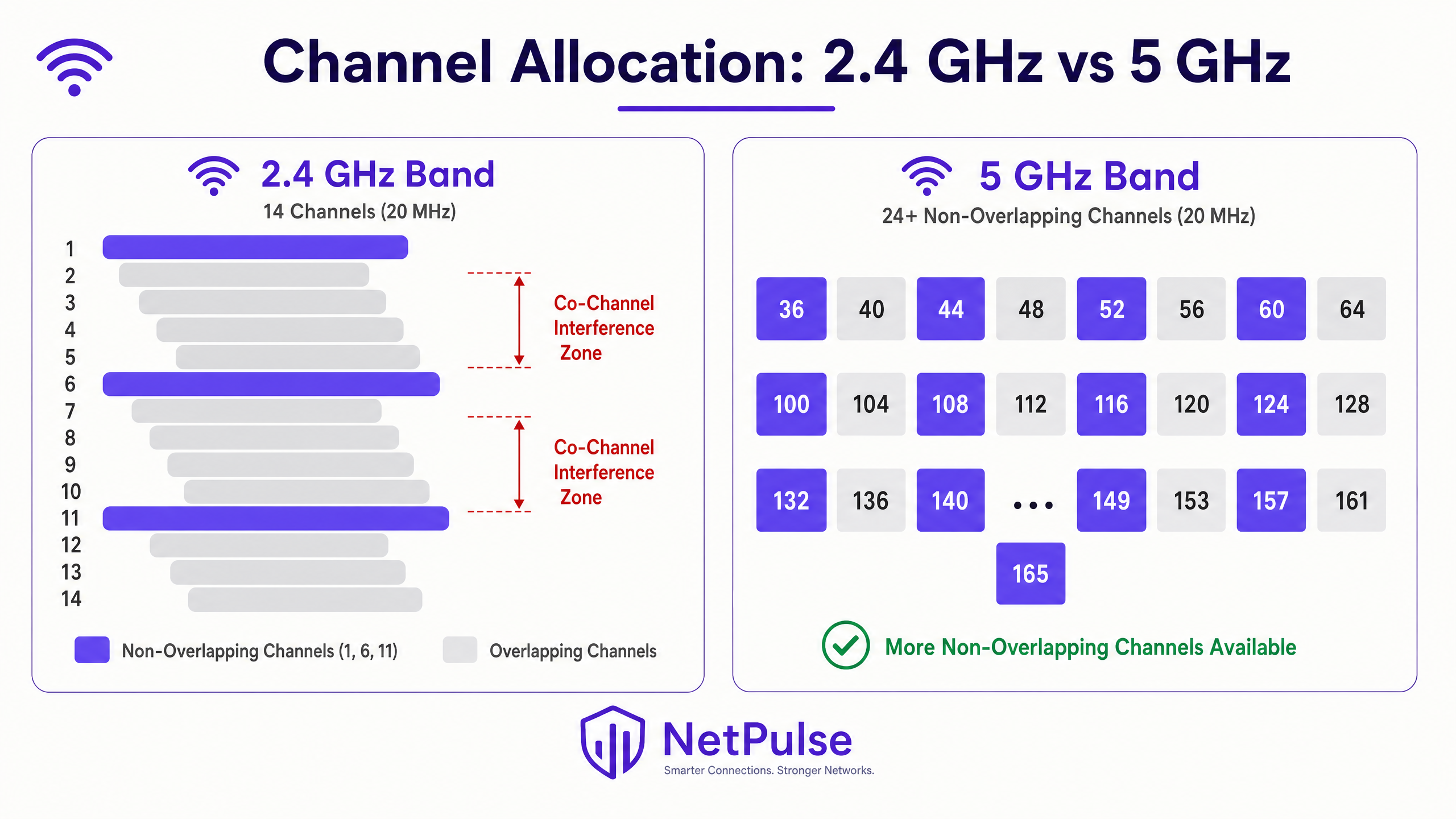
La banda de 2.4 GHz es notoriamente susceptible a la CCI debido a su espectro limitado. En la mayoría de los dominios regulatorios, solo hay tres canales no superpuestos (1, 6 y 11) utilizando anchos de canal de 20 MHz. En implementaciones de alta densidad — como pisos de tiendas minoristas, alas de conferencias de hoteles o pasillos de estadios — reutilizar estos tres canales sin causar superposición es un desafío matemático que no puede resolverse solo con la ubicación de los APs.
La banda de 5 GHz ofrece un alivio significativo, proporcionando 24 o más canales de 20 MHz no superpuestos, dependiendo de las regulaciones regionales de Selección Dinámica de Frecuencia (DFS). Sin embargo, la tentación de usar canales más anchos — 40 MHz, 80 MHz o 160 MHz — para lograr tasas de datos pico más altas a menudo reintroduce la CCI. Con anchos de canal de 80 MHz, el número de canales no superpuestos en la banda de 5 GHz se reduce de 24 a aproximadamente seis. Para implementaciones empresariales, estandarizar en canales de 20 MHz en 2.4 GHz y canales de 20 MHz o 40 MHz en 5 GHz es una mejor práctica fundamental para maximizar la reutilización de canales y minimizar la interferencia. Para más contexto sobre el uso moderno del espectro, revise Wi Fi Frequencies: A Guide to Wi-Fi Frequencies in 2026 .
La banda de 6 GHz introducida por Wi-Fi 6E (IEEE 802.11ax) y Wi-Fi 7 (IEEE 802.11be) proporciona 59 canales adicionales de 20 MHz no superpuestos, lo que representa una oportunidad transformadora para implementaciones de alta densidad. Sin embargo, la adopción de 6 GHz requiere actualizaciones de hardware tanto para AP como para clientes, lo que la convierte en una inversión a medio plazo en lugar de una solución inmediata para la infraestructura existente.
Guía de Implementación
Paso 1: Realizar un Estudio de Sitio RF Exhaustivo
Antes de realizar cualquier cambio de configuración, establezca una línea base. Un estudio de sitio RF activo y pasivo es fundamental. Los estudios pasivos capturan el entorno RF existente — fuerza de la señal, nivel de ruido, utilización del canal y fuentes de interferencia — sin conectarse a la red. Los estudios activos miden el rendimiento real y el comportamiento de roaming. Este no es un evento único; los entornos cambian. Las estructuras temporales en lugares de hospitalidad, los cambios estacionales de inventario en el comercio minorista o el nuevo equipo en entornos de atención médica pueden alterar significativamente la propagación de RF.
Herramientas como Ekahau, NetSpot o aplicaciones de estudio específicas del proveedor proporcionan la visualización necesaria para identificar zonas de interferencia, brechas de cobertura y conflictos de canales. El resultado de un estudio de sitio debe informar directamente la ubicación de los APs, la asignación de canales y la configuración de la potencia de transmisión.
Paso 2: Optimizar la Potencia de Transmisión (Tx Power)
Una idea errónea común es que aumentar la potencia de transmisión del AP mejora la cobertura y resuelve los problemas de conectividad. En realidad, exacerba la CCI. Si la señal de un AP llega más lejos de lo necesario, interfiere con los APs vecinos.ng celdas y crea un entorno de RF asimétrico.
Coincidir con las Capacidades del Cliente: Los dispositivos móviles (smartphones, tablets) suelen transmitir a 10–15 dBm. Si un AP transmite a 25 dBm, el cliente puede escuchar al AP claramente, pero el AP tiene dificultades para escuchar al cliente — el clásico problema del nodo oculto. Esto lleva a retransmisiones, una reducción del rendimiento efectivo y un aumento de la utilización del canal.
Pautas para el Ajuste de Potencia:
| Banda | Potencia de Tx Recomendada | Razón |
|---|---|---|
| 2.4 GHz | 10–14 dBm | Coincide con la capacidad de Tx del smartphone; reduce el tamaño de la celda |
| 5 GHz | 14–17 dBm | Ligeramente superior para compensar la pérdida de trayectoria a mayor frecuencia |
| 6 GHz | 17–20 dBm | Una mayor pérdida de trayectoria requiere un poco más de potencia |
La potencia de 2.4 GHz generalmente debe ser 3–6 dB menor que la de 5 GHz para fomentar la dirección de banda, empujando a los clientes capaces a la banda de 5 GHz menos congestionada.
Paso 3: Implementar la Gestión Dinámica de Radio
Los controladores WLAN empresariales modernos cuentan con algoritmos de gestión dinámica de radio — Radio Resource Management (RRM) de Cisco, Adaptive Radio Management (ARM) de Aruba, y equivalentes de Juniper Mist, Extreme Networks, entre otros. Estos sistemas monitorean continuamente el entorno de RF y ajustan dinámicamente las asignaciones de canal y la potencia de transmisión para mitigar la CCI.
Sin embargo, estos sistemas requieren una sintonización cuidadosa. Depender completamente de la configuración automática predeterminada en un entorno de alta densidad como un estadio o un centro de transporte a menudo conduce a la inestabilidad. Los parámetros clave de sintonización incluyen:
- Umbral de Cambio de Canal: El nivel de interferencia requerido para activar un cambio de canal. Si se establece demasiado bajo, el sistema cambia de canal constantemente en respuesta a interferencias transitorias (hornos de microondas, dispositivos Bluetooth), causando desconexiones de clientes.
- Intervalo de Cambio de Potencia: Con qué frecuencia el sistema ajusta la potencia de transmisión. En entornos estables, los ajustes menos frecuentes reducen la interrupción del cliente.
- Límites Mínimos y Máximos de Potencia: Límites estrictos que impiden que el algoritmo establezca niveles de potencia fuera de sus parámetros de diseño.
Paso 4: Desactivar las Tasas de Datos Básicas Heredadas
Si su radio de 2.4 GHz todavía tiene 1, 2, 5.5 y 11 Mbps habilitados como tasas básicas (obligatorias), los marcos de gestión — balizas, respuestas de sondeo y acuses de recibo — se transmiten a estas bajas tasas. Una sola baliza a 1 Mbps consume 10 veces el tiempo de aire de la misma baliza a 11 Mbps. En cientos de APs y miles de clientes, esta sobrecarga es significativa.
Desactivar las tasas por debajo de 12 Mbps obliga a todos los marcos de gestión y datos a utilizar una modulación más eficiente. También reduce eficazmente la celda de cobertura del AP, ya que solo los clientes lo suficientemente cerca para alcanzar 12 Mbps o más pueden asociarse. Esto crea un mecanismo natural para reducir la huella de CCI de cada AP.
Paso 5: Implementar 802.11k/v/r para un Roaming sin Interrupciones
Los clientes "pegajosos" — dispositivos que se niegan a conectarse a un AP más cercano — son un factor importante de la CCI. Un cliente asociado a un AP distante con una baja tasa de datos consume un tiempo de aire desproporcionado, degradando el rendimiento para todos los demás clientes en ese canal.
- 802.11k (Medición de Recursos de Radio): Proporciona a los clientes un informe de vecinos, informándoles de los APs cercanos y sus intensidades de señal.
- 802.11v (Gestión de Transición BSS): Permite a la red enviar sugerencias de roaming a los clientes, pidiéndoles efectivamente que se muevan a un AP mejor.
- 802.11r (Transición Rápida BSS): Reduce la latencia del roaming preautenticando a los clientes con los APs de destino, lo cual es crítico para aplicaciones de voz y video.
Estos protocolos trabajan en conjunto para asegurar que los clientes estén siempre asociados con el AP óptimo, reduciendo el consumo de tiempo de aire por cliente y mitigando la CCI.
Mejores Prácticas
Desactivar Tasas de Datos Básicas Inferiores: Desactivar las tasas de datos heredadas (1, 2, 5.5 y 11 Mbps) obliga a los clientes a utilizar esquemas de modulación más eficientes. Esto reduce el tiempo de aire requerido para los marcos de gestión y la transmisión de datos, reduciendo eficazmente la celda de cobertura efectiva del AP. Esta es una optimización fundamental para cualquier implementación empresarial moderna, como se detalla en Office Wi Fi: Optimize Your Modern Office Wi-Fi Network .
Aprovechar los Canales DFS: En la banda de 5 GHz, utilice los canales de Selección Dinámica de Frecuencia (DFS) (52–144 en la mayoría de los dominios regulatorios) para expandir el espectro no superpuesto disponible. Asegúrese de que sus APs y dispositivos cliente soporten DFS, y monitoree los eventos de radar que puedan forzar cambios de canal. En entornos donde los eventos de radar son frecuentes (cerca de aeropuertos o instalaciones militares), considere restringirse a canales no DFS.
Ubicación Estratégica de APs: Evite colocar APs en pasillos largos donde las señales de RF se propagan sin obstáculos, creando el efecto de pasillo. En su lugar, coloque los APs dentro de las habitaciones o áreas de cobertura específicas donde se congregan los usuarios. Utilice la estructura física del edificio — paredes, pisos, estanterías — como atenuadores de RF naturales para crear límites de celda.
Considerar BLE para Servicios de Ubicación: Si implementa servicios basados en ubicación junto con WiFi, comprenda cómo Bluetooth Low Energy interactúa con su infraestructura inalámbrica. Consulte BLE Low Energy Explained for Enterprise para estrategias de integración detalladas que eviten la interferencia entre balizas BLE y radios WiFi.
Segmentar el Tráfico de Invitados y Corporativo: Asegúrese de que el tráfico de Guest WiFi esté correctamente segmentado de la infraestructura corporativa utilizando VLANs y SSIDs separados. Reducir el número de SSIDs transmitidos por AP (idealmente no más de tres) disminuye la sobrecarga de los marcos de gestión y mejora la eficiencia general del canal.
Solución de Problemas y Mitigación de Riesgos
El Problema del Cliente "Pegajoso"
Los clientes que se niegan a conectarse a un AP más cercano con una señal más fuerte contribuyen significativamente a la CCI. A medida que un cliente "pegajoso" se aleja, su tasa de datos disminuye, consumiendo más tiempo de aire para transmitir la misma cantidad de datos. Más allá de habilitar 802.11k/v, revise su porcentaje de superposición de celdas. Las celdas deben superponerse aproximadamente entre un 15 y un 20% para una itinerancia fluida. Una mayor superposición da a los clientes menos incentivos para itinerar hasta que la calidad de la señal ya esté gravemente degradada.
Puntos de Acceso No Autorizados
Los APs no autorizados introducidos por empleados o invitados —routers de consumo conectados a puertos Ethernet— pueden devastar un plan de canales cuidadosamente diseñado. Implemente Sistemas de Prevención de Intrusiones Inalámbricas (WIPS) continuos para detectar y suprimir APs no autorizados. Asegure que su postura de control de acceso a la red sea robusta y considere revisar recursos sobre la modernización de su infraestructura NAC: La lista de verificación para migrar de NAC heredado a NAC nativo de la nube o A Lista de Verificação para Migrar de NAC Legado para NAC Nativo da Nuvem .
Fuentes de Interferencia No-WiFi
No toda la interferencia proviene de otros APs. Hornos de microondas, dispositivos Bluetooth, monitores para bebés y teléfonos DECT operan en la banda de 2.4 GHz. Los analizadores de espectro pueden identificar estas fuentes de interferencia no-802.11, que los algoritmos RRM pueden malinterpretar como interferencia WiFi y responder de manera inapropiada. Identificar y eliminar o reubicar estas fuentes suele ser más efectivo que los cambios de canal.
Modos de Falla Comunes
| Modo de Falla | Causa Raíz | Mitigación |
|---|---|---|
| Altas tasas de reintento (>10%) | CCI o nodo oculto | Reducir potencia Tx; revisar plan de canales |
| Bajo rendimiento a pesar de señal fuerte | Demasiados clientes por AP; CCI | Añadir APs; reducir ancho de canal |
| Cambios constantes de canal | Umbrales RRM demasiado bajos | Aumentar umbral de interferencia |
| Clientes sin itinerancia | Sin 802.11k/v; superposición excesiva de celdas | Habilitar 802.11k/v; ajustar potencia Tx |
| Caídas intermitentes en 5 GHz | Evento de radar DFS | Monitorear eventos DFS; considerar canales no-DFS |
ROI e Impacto Comercial
Resolver la CCI ofrece retornos medibles y cuantificables. En un entorno minorista, la conectividad confiable permite transacciones fluidas en puntos de venta móviles, consultas de inventario en tiempo real y actualizaciones de señalización digital. Una sola interrupción del POS durante las horas pico de ventas puede costar miles de libras en ventas perdidas y disrupción operativa. En la hostelería, el rendimiento de la red influye directamente en las puntuaciones de las reseñas de los huéspedes en plataformas como TripAdvisor y Google, siendo la conectividad un factor de satisfacción del huésped que se clasifica constantemente entre los tres primeros.
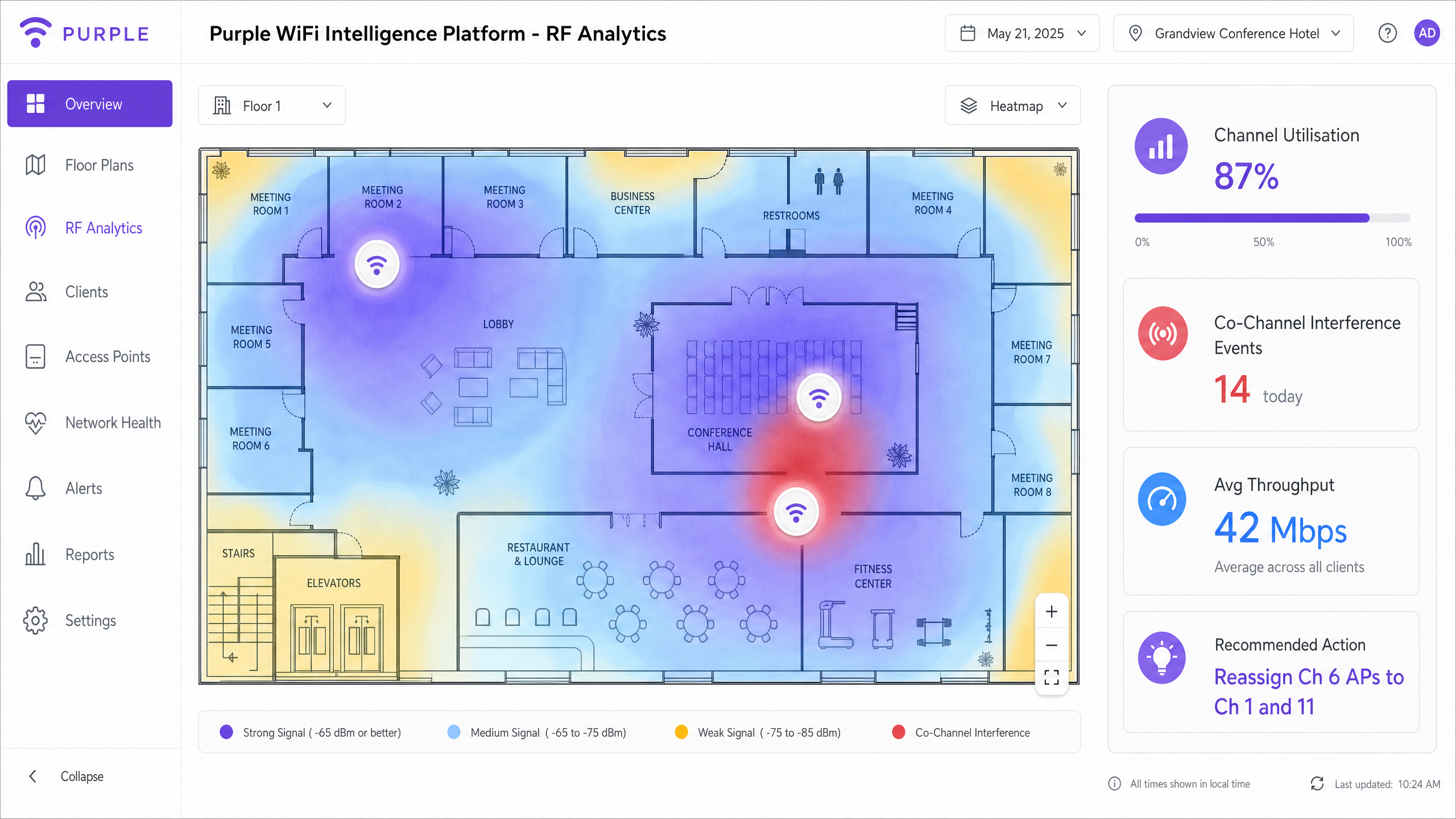
Al aprovechar WiFi Analytics para monitorear continuamente la utilización del canal, el número de clientes por AP, las tasas de reintento y los eventos de interferencia, los equipos de TI pueden pasar de la resolución de problemas reactiva a la gestión proactiva de la red. Los indicadores clave de rendimiento a seguir después de la remediación incluyen:
- Utilización del Canal: Apuntar por debajo del 50% para un rendimiento confiable; por encima del 70% indica un problema de capacidad.
- Tasa de Reintento: Apuntar por debajo del 5%; por encima del 10% indica interferencia significativa o problemas de cobertura.
- Rendimiento Promedio del Cliente: Establecer una línea base antes y después de los cambios para cuantificar la mejora.
- Volumen de Tickets de Soporte: Los tickets relacionados con WiFi deberían disminuir de manera medible dentro de los 30 días posteriores a la remediación.
La inversión en un estudio de sitio de RF profesional y la remediación del plan de canales generalmente se amortiza en uno o dos trimestres gracias a la reducción de los gastos generales de soporte de TI y la mejora de la continuidad operativa.
Definiciones clave
Co-Channel Interference (CCI)
Interference caused when multiple access points and clients operate on the same frequency channel, forcing them to share airtime via CSMA/CA and wait for the channel to clear before transmitting. CCI scales with the number of APs on the same channel.
The primary cause of degraded performance in dense deployments. Often misdiagnosed as an 'internet speed' or 'bandwidth' issue by end-users and non-technical stakeholders.
Adjacent-Channel Interference (ACI)
Interference caused by overlapping frequency bands — for example, using channels 1 and 3 simultaneously in the 2.4 GHz band. Unlike CCI, ACI is caused by spectral overlap rather than channel sharing.
Easily avoided by adhering strictly to non-overlapping channels (1, 6, 11 in 2.4 GHz). ACI is less common in well-managed enterprise networks but frequently seen in environments with rogue APs.
Carrier Sense Multiple Access with Collision Avoidance (CSMA/CA)
The protocol WiFi uses to manage access to the RF medium. Devices must listen for a clear channel before transmitting, and use random backoff timers to avoid simultaneous transmissions.
Understanding CSMA/CA is fundamental to understanding why CCI destroys throughput. It is a polite, orderly protocol that fails under heavy contention — the more devices sharing a channel, the longer each must wait.
Dynamic Frequency Selection (DFS)
A regulatory mechanism that allows WiFi devices to share spectrum with radar systems in the 5 GHz band. APs must monitor for radar signals and vacate the channel within 10 seconds if detected.
Crucial for enterprise deployments to unlock additional non-overlapping channels in the 5 GHz band. Requires careful monitoring; unexpected DFS events can cause client disconnects if not managed properly.
Hidden Node Problem
Occurs when two client devices can hear the AP but cannot hear each other, leading them to transmit simultaneously and cause collisions at the AP. Results in high retry rates and reduced throughput.
Often caused by APs transmitting at significantly higher power levels than client devices. Mitigated by matching AP Tx power to client Tx capability.
Radio Resource Management (RRM)
Automated systems within enterprise WLAN controllers that dynamically adjust channel assignments and transmit power based on continuous RF monitoring. Examples include Cisco RRM and Aruba ARM.
Useful in dynamic environments but requires careful threshold tuning. Default settings are rarely optimal for high-density venues and can cause instability if too aggressive.
Airtime Fairness
A WLAN feature that allocates equal transmission time to all associated clients, regardless of their data rate. Prevents slower (legacy or distant) clients from monopolising the channel at the expense of faster clients.
Critical in mixed-device environments (e.g., a hotel with both modern smartphones and legacy IoT sensors). Without airtime fairness, a single slow client can halve the effective throughput for all other clients on the channel.
BSS Transition Management (802.11v)
An IEEE 802.11 protocol that allows a WLAN controller to send roaming suggestions to client devices, recommending they associate with a different (closer or less congested) AP.
Part of the 802.11k/v/r suite of roaming protocols. Directly addresses the sticky client problem by giving the network a mechanism to influence client roaming decisions.
Channel Utilisation
The percentage of time a given RF channel is occupied by transmissions (both 802.11 and non-802.11). A key metric for diagnosing CCI.
Target below 50% for reliable performance. Above 70% indicates a capacity problem requiring channel plan remediation or additional AP density with reduced cell sizes.
Ejemplos resueltos
A 400-room luxury hotel is experiencing severe connectivity issues in the conference centre during a major tech summit. 800 attendees report slow speeds and frequent disconnects despite dense AP placement. The IT team has already tried rebooting all APs.
Step 1: Conduct an immediate spectrum analysis using a laptop-based tool (Ekahau, Metageek Chanalyzer) to baseline channel utilisation and interference levels. The analysis reveals 2.4 GHz channel utilisation at 94% and significant CCI on 5 GHz due to 80 MHz channel widths across all APs.
Step 2: Disable 2.4 GHz radios on every other AP in the high-density conference area. With 800 devices in a confined space, the 2.4 GHz band is beyond saturation. Reducing the number of competing APs on three channels immediately reduces contention.
Step 3: Reduce 5 GHz channel widths from 80 MHz to 20 MHz across all conference centre APs. This increases available non-overlapping channels from approximately 6 to 24, allowing each AP to operate on a unique channel.
Step 4: Lower AP transmit power to 12 dBm (2.4 GHz) and 15 dBm (5 GHz) to shrink cell sizes and encourage clients to associate with the nearest AP rather than a distant one.
Step 5: Disable basic data rates below 12 Mbps on all radios.
Step 6: Validate with a post-change spectrum analysis. Channel utilisation should drop below 60% and retry rates below 8%.
A national retail chain has deployed APs down the centre of every aisle in a large warehouse-style store. Staff report poor roaming on handheld scanners and persistent connectivity drops near the loading bay.
Step 1: Conduct a passive RF survey to visualise coverage and identify the hallway effect. The survey confirms that APs at opposite ends of 60-metre aisles are on the same channel and interfering with each other.
Step 2: Relocate APs to a staggered deployment pattern, positioning them above the racking rather than in the aisle centre. This uses the metal racking as a natural RF attenuator, creating distinct coverage cells per aisle section.
Step 3: Implement directional antennas (downtilt patch antennas) on specific APs near the loading bay to focus RF energy downward and limit horizontal propagation into adjacent cells.
Step 4: Adjust RRM profiles to react less aggressively to transient interference from loading bay equipment (forklifts, metal doors).
Step 5: Enable 802.11k and 802.11v on the WLAN controller to assist handheld scanner roaming decisions.
Step 6: Validate roaming performance by walking the floor with a handheld scanner and monitoring association events in the WLAN controller.
Preguntas de práctica
Q1. You are designing the WiFi network for a new high-density university lecture hall with 500 seats. The architect insists on hiding all APs above a metal-mesh drop ceiling for aesthetic reasons. The university requires reliable 4K video streaming for remote lectures. How do you address the architectural constraint without compromising RF performance?
Sugerencia: Consider the impact of metal mesh on RF propagation, the resulting requirement for Tx power, and the asymmetric coverage problem this creates.
Ver respuesta modelo
The metal mesh will severely attenuate the RF signal, potentially by 10–20 dB depending on mesh density. To compensate, APs would need to transmit at maximum power, which increases CCI in adjacent spaces and creates a significant hidden node problem for clients trying to transmit back through the mesh. The recommended approach is to negotiate the use of APs with external directional antennas (downtilt patch antennas) mounted below the ceiling tile, with the AP body concealed above the mesh. Alternatively, specify aesthetically designed APs (e.g., Cisco Meraki or Aruba with low-profile enclosures) that can be mounted flush below the ceiling. If the architect is immovable on the metal mesh, specify APs with external antenna ports and route antenna cables through the mesh to below-ceiling mounting points. Under no circumstances should RF design be compromised for aesthetics when 4K streaming reliability is a stated requirement.
Q2. A retail client is upgrading their POS tablets to a new model that only supports 2.4 GHz WiFi. They currently operate a well-managed dual-band network with 30 APs in a medium-sized store. What changes should you make to accommodate the new tablets without degrading overall network performance for other devices?
Sugerencia: Focus on band steering, basic data rates, and the impact of adding 2.4 GHz-only devices to an already constrained band.
Ver respuesta modelo
First, ensure band steering is aggressively enabled to push all capable devices (smartphones, modern laptops) to the 5 GHz band, clearing airtime on 2.4 GHz for the POS tablets. Second, audit the 2.4 GHz channel plan to ensure strict adherence to channels 1, 6, and 11 with no deviations. Third, disable basic data rates below 12 Mbps on the 2.4 GHz band to force the POS tablets to transmit more efficiently, reducing their airtime consumption per transaction. Fourth, consider disabling 2.4 GHz radios on select APs if the density is too high — creating fewer, larger 2.4 GHz cells while maintaining dense 5 GHz coverage. Finally, monitor 2.4 GHz channel utilisation post-deployment and set an alert threshold at 60% to catch degradation before it impacts POS performance.
Q3. After deploying a new WLAN controller, the automated Radio Resource Management feature is constantly changing channels every 15–20 minutes, causing brief disconnects for VoIP users and complaints from the operations team. The IT manager wants to disable RRM entirely. What is your recommendation?
Sugerencia: Consider the trade-off between RRM stability and the long-term benefit of automated channel management in a dynamic environment.
Ver respuesta modelo
Disabling RRM entirely is not recommended. Without automated channel management, the network will gradually degrade as the RF environment changes (new equipment, seasonal changes, rogue APs). The correct approach is to tune the RRM thresholds rather than disable the feature. Increase the interference threshold required to trigger a channel change — the algorithm is currently reacting to transient interference that does not warrant a channel change. Extend the minimum time between channel changes to at least 60 minutes. Consider implementing a scheduled maintenance window for channel changes, restricting automated changes to off-peak hours (e.g., 02:00–04:00). Enable event logging for all RRM-triggered changes to identify the specific interference source causing the frequent triggers. Once the root cause is identified (often a non-WiFi interference source like a microwave or DECT phone), address it directly.