How to Identify and Resolve Co-Channel Interference (CCI)
Co-channel interference (CCI) is the leading cause of degraded throughput and elevated latency in high-density enterprise WiFi deployments, occurring when multiple access points share the same frequency channel and are forced into CSMA/CA contention. This guide provides network architects, IT managers, and venue operations directors with a structured, vendor-neutral framework for identifying CCI through RF diagnostics and analytics, and resolving it through channel planning, transmit power optimisation, data rate management, and physical AP placement. Mastering CCI resolution is a prerequisite for delivering reliable guest WiFi, operational connectivity, and measurable ROI across hotels, retail chains, stadiums, and public-sector facilities.
Listen to this guide
View podcast transcript

कार्यकारी सारांश (Executive Summary)
को-चॅनेल इंटरफेरन्स (CCI) हा हाय-डेन्सिटी एंटरप्राइझ वायरलेस डिप्लॉयमेंट्समधील सर्वात व्यापक आणि चुकीचा समजला जाणारा परफॉर्मन्स अडथळा आहे. जेव्हा एकाच फ्रिक्वेन्सी चॅनेलवर कार्यरत असलेले दोन किंवा अधिक ॲक्सेस पॉइंट्स एकमेकांच्या क्लिअर चॅनेल असेसमेंट (CCA) रेंजमध्ये येतात, तेव्हा हे घडते. यामुळे त्या चॅनेलवरील सर्व डिव्हाइसेसना CSMA/CA द्वारे नियंत्रित कंटेंशन क्यूमध्ये जाणे भाग पडते. याचा परिणाम कव्हरेज फेल्युअरमध्ये होत नाही — सिग्नलची ताकद चांगली दिसू शकते — तर कॅपॅसिटी कोलमडण्यात होतो: एकूण थ्रूपुट कमी होतो, रिट्राय रेट वाढतात आणि लोड असताना लेटन्सी अनपेक्षितपणे वाढते.
हॉस्पिटॅलिटी , रिटेल आणि इव्हेंट्समधील व्हेन्यू ऑपरेटर्ससाठी, याचा थेट व्यावसायिक परिणाम होतो. २०० खोल्यांचे हॉटेल जिथे प्रत्येक फ्लोअरवरील AP चॅनेल ६ शेअर करतो, तिथे पीक चेक-इन कालावधीत पाहुण्यांच्या समाधानाचा स्कोअर कमी होईल. रिटेल वातावरणात जिथे मोबाईल POS टर्मिनल्स गर्दीच्या २.४ GHz चॅनेलवर शेकडो खरेदीदारांच्या डिव्हाइसेसशी स्पर्धा करतात, तिथे सर्वात महत्त्वाच्या क्षणी ट्रान्झॅक्शन फेल्युअरचा धोका असतो.
याचे रिझोल्यूशन फ्रेमवर्क सुस्थापित आहे: क्लायंट्सना ५ GHz वर स्थलांतरित करणे, २० MHz किंवा ४० MHz चॅनेल विड्थ्स प्रमाणित करणे, क्लायंट डिव्हाइसच्या क्षमतेशी जुळण्यासाठी ट्रान्समिट पॉवर कमी करणे, लेगसी डेटा रेट्स निष्क्रिय करणे आणि इमारतीच्या संरचनेचा नैसर्गिक RF ॲटेन्युएटर्स म्हणून वापर करणे. Purple's WiFi Analytics सारखे ॲनालिटिक्स प्लॅटफॉर्म्स रिॲक्टिव्ह ट्रबलशूटिंगकडून प्रोॲक्टिव्ह RF मॅनेजमेंटकडे जाण्यासाठी आवश्यक असणारी सततची व्हिझिबिलिटी प्रदान करतात. हे मार्गदर्शक प्रोडक्शन वातावरणात ते फ्रेमवर्क अंमलात आणण्यासाठी तांत्रिक खोली आणि अंमलबजावणीची विशिष्टता प्रदान करते.
तांत्रिक सखोल विश्लेषण (Technical Deep-Dive)
को-चॅनेल इंटरफेरन्सचे भौतिकशास्त्र (The Physics of Co-Channel Interference)
Wi-Fi हे IEEE 802.11 मानकाद्वारे नियंत्रित सामायिक, हाफ-डुप्लेक्स माध्यम म्हणून कार्य करते. करिअर सेन्स मल्टिपल ॲक्सेस विथ कोलिजन अव्हायडन्स (CSMA/CA) प्रोटोकॉलनुसार प्रत्येक डिव्हाइसला — ॲक्सेस पॉइंट्स आणि क्लायंट स्टेशन्स दोन्ही — ट्रान्समिट करण्यापूर्वी क्लिअर चॅनेल असेसमेंट करणे आवश्यक असते. चॅनेल व्यस्त असल्याचे आढळल्यास (CCA थ्रेशोल्डच्या वर, सामान्यतः 802.11n आणि नंतरच्या आवृत्तीसाठी -८२ dBm), डिव्हाइस ट्रान्समिशन पुढे ढकलते आणि रँडम बॅकऑफ कालावधीत प्रवेश करते.
जेव्हा एकाच चॅनेलवर कार्यरत असलेले दोन किंवा अधिक AP एकमेकांच्या CCA रेंजमध्ये असतात तेव्हा CCI उद्भवतो. IEEE 802.11 स्पेसिफिकेशननुसार, जर नॉईज फ्लोअरच्या वर ४ dB वर 802.11 प्रिएम्बल आढळला, तर रिसिव्हिंग स्टेशनने ट्रान्समिशन पुढे ढकलले पाहिजे. एका दाट डिप्लॉयमेंटमध्ये, याचा अर्थ असा आहे की ५०-मीटरच्या त्रिज्येतील चॅनेल ३६ वरील प्रत्येक AP त्याच्या संपूर्ण कव्हरेज झोनमधील सर्व ट्रान्समिशन प्रभावीपणे अनुक्रमित (serialising) करत आहे. जितके जास्त AP चॅनेल शेअर करतील, तितका प्रत्येक डिव्हाइसला जास्त वेळ वाट पाहावी लागेल आणि प्रति क्लायंट प्रभावी थ्रूपुट कमी होईल.
हे मूलभूतपणे कव्हरेजच्या समस्येपेक्षा वेगळे आहे. चॅनेल वाटप (channel allocation) न बदलता — फक्त अधिक APs जोडून CCI च्या लक्षणांवर उपाय शोधण्याचा प्रयत्न करणारी IT टीम परिस्थिती सुधारण्याऐवजी ती अधिक बिघडवेल.
CCI विरुद्ध Adjacent-Channel Interference (ACI)
या दोन बिघाडांच्या प्रकारांमध्ये अनेकदा गल्लत केली जाते, परंतु त्यांच्यासाठी वेगवेगळ्या निवारण धोरणांची आवश्यकता असते.
| पॅरामीटर | Co-Channel Interference (CCI) | Adjacent-Channel Interference (ACI) |
|---|---|---|
| कारण | CCA रेंजमध्ये एकाच चॅनेलवर अनेक APs असणे | ओव्हरलॅप होणाऱ्या परंतु भिन्न चॅनेलवर APs असणे (उदा. Ch 1 आणि Ch 2) |
| कार्यपद्धती | CSMA/CA स्पर्धा — डिव्हाइसेस थांबतात आणि वाट पाहतात | अंशतः फ्रिक्वेन्सी ओव्हरलॅपमुळे सिग्नल खराब होतो |
| शोध | उच्च चॅनेल वापर, वाढलेला रिट्राय दर, लोड असताना कमी थ्रुपुट | खराब झालेले फ्रेम्स, उच्च त्रुटी दर, खराब SNR |
| प्राथमिक उपाय | चॅनेलचा पुनर्वापर नियोजन, पॉवर कमी करणे, बँड स्टीयरिंग | ओव्हरलॅप न होणाऱ्या चॅनेलचा वापर करणे (2.4 GHz मध्ये 1, 6, 11) |
| दाट उपयोजनांमधील तीव्रता | अत्यंत उच्च — AP च्या घनतेनुसार वाढते | मध्यम — योग्य चॅनेल निवडीसह टाळता येण्याजोगे |
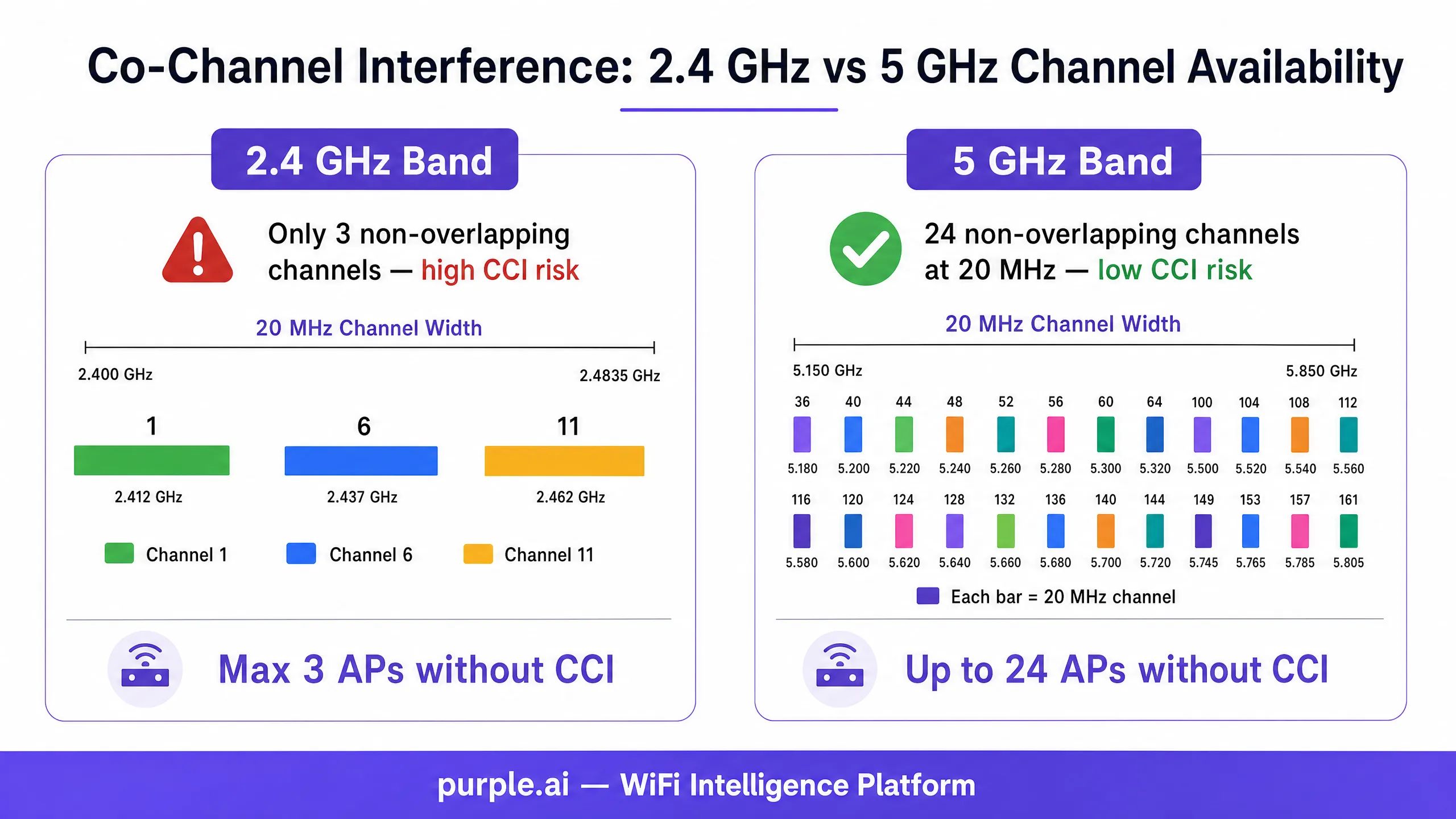
2.4 GHz बँडमध्ये, केवळ तीन ओव्हरलॅप न होणारे 20 MHz चॅनेल्स आहेत: 1, 6, आणि 11. 2.4 GHz वर परस्पर CCA रेंजमध्ये तीनपेक्षा जास्त APs असलेले कोणतेही उपयोजन असल्यास व्याख्यानुसार तिथे CCI चा अनुभव येईल. 5 GHz बँडमध्ये, 24 पर्यंत ओव्हरलॅप न होणारे 20 MHz चॅनेल्स उपलब्ध आहेत (प्रादेशिक नियामक निर्बंध आणि DFS आवश्यकतांच्या अधीन), ज्यामुळे दाट उपयोजनांसाठी हा प्राथमिक बँड बनतो.
चॅनेलची रुंदी: छुपे CCI गुणक
एंटरप्राइझ उपयोजनांमधील सर्वात सामान्य कॉन्फिगरेशन त्रुटींपैकी एक म्हणजे 5 GHz बँडमध्ये 80 MHz किंवा 160 MHz चॅनेल रुंदीचा वापर करणे. जरी रुंद चॅनेल्स वैयक्तिक क्लायंटसाठी उच्च पीक थ्रुपुट देतात — जे विक्रेत्यांच्या बेंचमार्क चाचण्यांमध्ये आकर्षक वाटते — तरीही ते उपलब्ध ओव्हरलॅप न होणाऱ्या चॅनेल्सची संख्या कमालीची कमी करतात.
| चॅनेलची रुंदी | ओव्हरलॅप न होणारे 5 GHz चॅनेल्स (US) | ओव्हरलॅप न होणारे 5 GHz चॅनेल्स (EU) |
|---|---|---|
| 20 MHz | 24 | 19 |
| 40 MHz | 12 | 9 |
| 80 MHz | 6 | 4 |
| 160 MHz | 2 | 1 |
तीन मजल्यांवर पसरलेल्या 60 APs असलेल्या ठिकाणी, 80 MHz चॅनेल्स वापरल्याने उपलब्ध ओव्हरलॅप न होणाऱ्या चॅनेल्सचा पूल 24 वरून 6 वर येतो. प्रति मजला 10 APs असल्यास, प्रत्येक चॅनेलचा प्रति मजला अंदाजे 1.7 वेळा पुनर्वापर करावा लागतो — ज्यामुळे CCI ची खात्री असते. 20 MHz चॅनेल्सवर स्विच केल्याने पुनर्वापर आवश्यक होण्यापूर्वी 24 पर्यंत युनिक चॅनेल वाटप करता येतात, ज्यामुळे चॅनेल पुनर्वापर अंतरामध्ये 4 पट सुधारणा होते.
एंटरप्राइझ उपयोजनांसाठी योग्य दृष्टीकोन म्हणजे 2.4 GHz मध्ये 20 MHz चॅनेल्स (अनिवार्य) आणि 5 GHz मध्ये 20 MHz किंवा 40 MHz चॅनेल्स प्रमाणित करणे. 80 MHz हे 6 GHz उपयोजनांसाठी (Wi-Fi 6E आणि Wi-Fi 7) राखीव ठेवा जेथे विस्तारित स्पेक्ट्रम — US मध्ये 59 पर्यंत ओव्हरलॅप न होणारे 20 MHz चॅनेल्स — पुरेशी जागा प्रदान करतो.
ट्रान्समिट पॉवर आणि हिडन नोड समस्या
एंटरप्राइझ डिप्लॉयमेंट्समध्ये हाय ट्रान्समिट पॉवर हा CCI वाढवणारा दुसरा सर्वात सामान्य घटक आहे. "अधिक पॉवर म्हणजे उत्तम कव्हरेज" हा समज वैयक्तिकरित्या योग्य असला, तरी मल्टि-AP वातावरणात तो अत्यंत चुकीचा ठरतो.
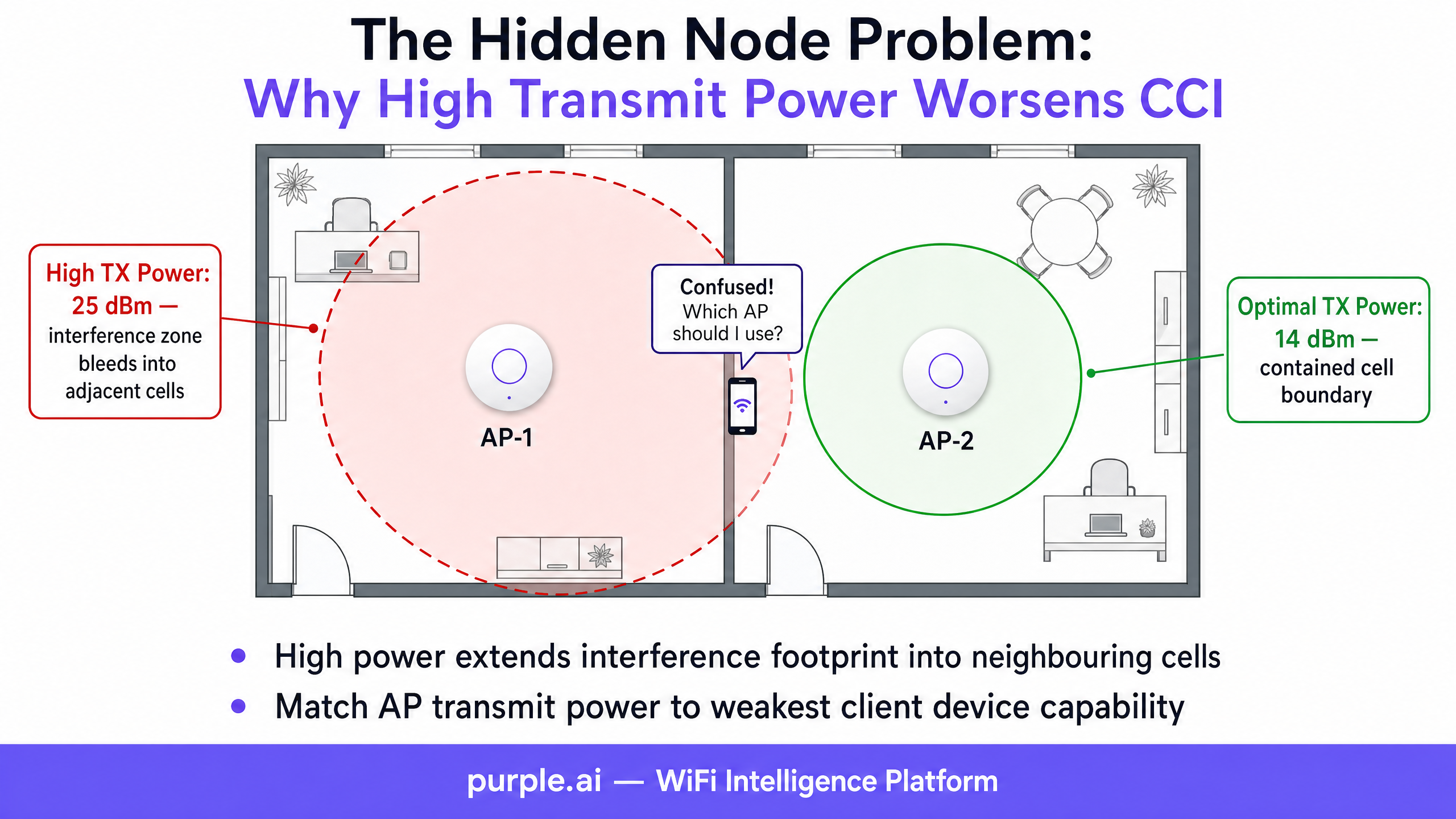
हिडन नोड समस्या ही AP आणि क्लायंट ट्रान्समिट पॉवरमधील विषमतेमुळे उद्भवते. छतावर बसवलेला एंटरप्राइझ AP कदाचित 20–25 dBm वर ट्रान्समिट करू शकतो, तर सामान्य स्मार्टफोन 12–15 dBm वर ट्रान्समिट करतो. AP क्लायंटचा आवाज ऐकू शकतो, परंतु क्लायंटचा सिग्नल शेजारील APs पर्यंत पोहोचण्याइतका लांब जात नाही. ते शेजारील APs — क्लायंट ट्रान्समिट करत असल्याची माहिती नसताना — स्वतःचे ट्रान्समिशन एकाच वेळी सुरू करू शकतात, ज्यामुळे इच्छित AP वर कोलिजन (collisions) होतात.
शिवाय, हाय-पॉवर AP त्याचे CCA फूटप्रिंट खूप मोठ्या भौतिक क्षेत्रावर विस्तारित करतो, ज्यामुळे अधिक डिव्हाइसेस त्याच्या कंटेंशन डोमेनमध्ये येण्यास भाग पडतात. 25 dBm वर ट्रान्समिट करणारा AP 80-100 मीटर त्रिज्येचा CCA झोन तयार करू शकतो, ज्यामध्ये अनेक मजल्यांवरील आणि शेजारील खोल्यांमधील APs समाविष्ट होतात. ट्रान्समिट पॉवर 14 dBm पर्यंत कमी केल्याने तो झोन 30-40 मीटरपर्यंत मर्यादित होतो, ज्यामुळे संपूर्ण ठिकाणी एकाच वेळी बरेच ट्रान्समिशन करणे शक्य होते.
एंटरप्राइझ डिप्लॉयमेंट्ससाठी शिफारस केलेले ट्रान्समिट पॉवर टार्गेट्स 2.4 GHz साठी 10–14 dBm आणि 5 GHz साठी 14–17 dBm आहेत. या आकड्यांकडे सुरुवातीचे बिंदू म्हणून पाहिले पाहिजे; इष्टतम मूल्य हे AP ची घनता, इमारतीचे साहित्य आणि वातावरणातील सर्वात कमकुवत क्रिटिकल क्लायंट डिव्हाइसच्या ट्रान्समिट पॉवर क्षमतेवर अवलंबून असते.
डेटा रेट मॅनेजमेंट आणि एअरटाइम कार्यक्षमता
लेगसी बेसिक डेटा रेट्स हे CCI मध्ये महत्त्वपूर्ण पण अनेकदा दुर्लक्षित योगदान देणारे घटक आहेत. 802.11 मानकांमध्ये, मॅनेजमेंट फ्रेम्स — बीकन्स, प्रोब रिस्पॉन्स आणि ॲकनॉलेजमेंट्स — सर्वात कमी अनिवार्य बेसिक रेटवर ट्रान्समिट केल्या जातात. जर 1 Mbps हा बेसिक रेट म्हणून सक्षम केला असेल, तर प्रत्येक बीकन आणि ॲकनॉलेजमेंट चॅनेलवर 54 Mbps च्या तुलनेत 54 पट जास्त वेळ घेते. हा मॅनेजमेंट फ्रेम ओव्हरहेड असा एअरटाइम वापरतो जो अन्यथा डेटा ट्रान्समिशनसाठी वापरला जाऊ शकतो, ज्यामुळे चॅनेलचा वापर प्रभावीपणे वाढतो आणि CCI ची समस्या अधिक गंभीर होते.
शिफारस केलेले कॉन्फिगरेशन म्हणजे 2.4 GHz मध्ये 12 Mbps पेक्षा कमी आणि 5 GHz मध्ये 24 Mbps पेक्षा कमी असलेले सर्व बेसिक रेट्स अक्षम करणे. हे मॅनेजमेंट फ्रेम्सना अधिक कार्यक्षम मॉड्युलेशन वापरण्यास भाग पाडते, प्रभावी सेल त्रिज्या कमी करते (केवळ 12 Mbps किंवा त्याहून अधिक मिळवण्याइतके जवळ असलेले क्लायंटच असोसिएट होऊ शकतात) आणि एकूण एअरटाइम कार्यक्षमता सुधारते. हाय-डेन्सिटी डिप्लॉयमेंट्समध्ये, हा एकच कॉन्फिगरेशन बदल चॅनेलचा वापर 15-25% ने कमी करू शकतो.
रेडिओ रिसोर्स मॅनेजमेंट (RRM) आणि ऑटोमेशन
आधुनिक एंटरप्राइझ WLAN कंट्रोलर्स — Cisco Catalyst Center (पूर्वीचे DNA Center), Aruba Central, Juniper Mist, आणि Extreme Networks ExtremeCloud — यामध्ये स्वयंचलित Radio Resource Management (RRM) क्षमता समाविष्ट असतात. हे सिस्टम्स चॅनेलचा वापर, इंटरफेरन्सची पातळी आणि AP लोडचे सतत निरीक्षण करतात, आणि CCI कमी करण्यासाठी चॅनेल असाइनमेंट्स आणि ट्रान्समिट पॉवर डायनॅमिकली ॲडजस्ट करतात.
RRM हे एक मौल्यवान साधन आहे, परंतु हाय-डेन्सिटी वातावरणात यासाठी काळजीपूर्वक ट्यूनिंग करणे आवश्यक आहे. डीफॉल्ट RRM कॉन्फिगरेशन्स हे सामान्य-उद्देशीय उपयोजनांसाठी डिझाइन केलेले असतात आणि ते तात्पुरत्या इंटरफेरन्स इव्हेंट्सवर — जसे की हॉटेलच्या किचनमध्ये मायक्रोवेव्ह ओव्हन सुरू होणे, किंवा तात्पुरत्या Bluetooth डिव्हाइसमुळे निर्माण होणारा थोड्या वेळाचा इंटरफेरन्स स्पाइक — अत्यंत आक्रमकपणे प्रतिक्रिया देऊ शकतात. ३० सेकंदांच्या इंटरफेरन्स इव्हेंटला प्रतिसाद म्हणून केलेला आक्रमक चॅनेल बदल ट्रान्झिशन दरम्यान सर्व संबंधित क्लायंट्सना विस्कळीत करेल, ज्यामुळे सपोर्ट तिकिटे आणि वापरकर्त्यांच्या तक्रारी वाढतील.
सुरुवातीच्या उपयोजनानंतर बेसलाइन स्थापित करण्यासाठी ५-७ दिवस RRM मॉनिटरिंग मोडमध्ये चालवणे आणि त्यानंतर खालील ट्यूनिंग पॅरामीटर्स लागू करणे ही सर्वोत्तम पद्धत आहे:
- किमान चॅनेल बदलण्याची वेळ (Minimum channel change interval): किमान ६० मिनिटे; स्थिर वातावरणासाठी १२० मिनिटे शिफारसित.
- चॅनेल बदलण्यासाठी इंटरफेरन्स थ्रेशोल्ड (Interference threshold for channel change): तात्पुरत्या इंटरफेरन्सला मिळणाऱ्या प्रतिक्रिया रोखण्यासाठी डीफॉल्ट (साधारणपणे १०%) वरून ३५-५०% पर्यंत वाढवा.
- ट्रान्समिट पॉवर ॲडजस्टमेंट संवेदनशीलता (Transmit power adjustment sensitivity): जलद पॉवर ऑसिलेशन रोखण्यासाठी "low" किंवा "medium" वर सेट करा.
- शेड्युल केलेले चॅनेल बदल (Scheduled channel changes): अंदाज लावता येण्याजोग्या ऑक्युपन्सी पॅटर्न असलेल्या वातावरणात (कॉन्फरन्स सेंटर्स, ऑफिसेस), चॅनेल बदल केवळ मेंटेनन्स विंडोजपुरते (स्थानिक वेळेनुसार ०२:००-०५:००) मर्यादित ठेवा.
Cisco RRM कॉन्फिगरेशनवरील व्हेंडर-विशिष्ट मार्गदर्शनासाठी, Cisco Wireless APs: 2026 Guide to Products & Deployment चा संदर्भ घ्या.
फिजिकल प्लेसमेंट: द हॉलवे इफेक्ट आणि स्ट्रक्चरल अटेन्युएशन
फिजिकल प्लेसमेंटच्या टप्प्यावरील RF डिझाइनमधील त्रुटी सॉफ्टवेअर कॉन्फिगरेशनद्वारे पूर्णपणे दुरुस्त केल्या जाऊ शकत नाहीत. हॉस्पिटॅलिटी आणि हेल्थकेअर वातावरणात सर्वात सामान्य फिजिकल प्लेसमेंट त्रुटी म्हणजे हॉलवे डिप्लॉयमेंट पॅटर्न: कॉरिडॉरच्या मध्यभागी ठराविक अंतराने माउंट केलेले APs.
८०-मीटर कॉरिडॉर असलेल्या हॉटेलमध्ये, कॉरिडॉरच्या एका टोकाला चॅनेल ३६ वर कार्यरत असलेल्या AP ची त्याच कॉरिडॉरच्या दुसऱ्या टोकावरील APs शी — जे देखील चॅनेल ३६ वर आहेत — थेट लाईन-ऑफ-साईट असेल, ज्यामध्ये अत्यंत कमी पाथ लॉस (path loss) होतो. याचा परिणाम चॅनेल प्लॅन कितीही काळजीपूर्वक डिझाइन केला असला तरीही, संपूर्ण फ्लोअरवर गंभीर CCI मध्ये होतो.
योग्य पद्धत म्हणजे APs गेस्ट रूम्स किंवा पेशंट बेजच्या आत, कॉरिडॉरच्या आलटून-पालटून बाजूला (staggered) माउंट करणे. यामुळे प्रत्येक AP तो ज्या खोलीत आहे त्या खोलीला आणि लगतच्या खोल्यांना कव्हर करतो, आणि खोलीच्या भिंती १०-१५ dB चे RF अटेन्युएशन प्रदान करतात ज्यामुळे एक नैसर्गिक सेल बाउंड्री तयार होते. ही पद्धत परस्पर CCA रेंजमधील APs ची संख्या संभाव्य १०-१५ (कॉरिडॉर डिप्लॉयमेंट) वरून २-४ (इन-रूम डिप्लॉयमेंट) पर्यंत कमी करते, ज्यामुळे CCI नाट्यमयरित्या कमी होते.
रिटेल आणि वेअरहाउस वातावरणात, रॅकिंगच्या रांगांच्या वर AP बसवणे — ऐवजी गल्लीबोळात बसवण्यापेक्षा — मेटल शेल्व्हिंगचा वापर नैसर्गिक RF ॲटेन्युएटर म्हणून करते. गल्लीच्या दिशेने खाली निर्देशित केलेले डायरेक्शनल अँटेना RF फूटप्रिंटला अधिक मर्यादित करतात, ज्यामुळे अनेक गल्ल्यांमध्ये इंटरफेरन्स पसरण्यास प्रतिबंध होतो.
अंमलबजावणी मार्गदर्शक
पायरी १: बेसलाइन RF मूल्यांकन
कोणतेही कॉन्फिगरेशन बदल करण्यापूर्वी, सर्वसमावेशक RF बेसलाइन मूल्यांकन करा. सर्व उपयोजित APs मधील चॅनेल वापर, नॉईज फ्लोअर आणि इंटरफेरन्सचे स्रोत कॅप्चर करण्यासाठी स्पेक्ट्रम ॲनालायझर (Ekahau Sidekick, MetaGeek Chanalyzer, किंवा समतुल्य) वापरा. कॅप्चर करायचे मुख्य मेट्रिक्स:
- प्रति AP चॅनेल वापर: ५०% पेक्षा जास्त वापर असलेल्या कोणत्याही AP ला CCI जोखीम म्हणून चिन्हांकित करा.
- प्रति AP रिट्राय दर: १०% पेक्षा जास्त रिट्राय दर हे कॉन्टेंशन किंवा इंटरफेरन्स दर्शवतात.
- सिग्नल-टू-नॉईज रेशो (SNR): डेटा क्लायंटसाठी लक्ष्य SNR > २५ dB; व्हॉइस आणि व्हिडिओसाठी > ३५ dB.
- प्रति चॅनेल को-चॅनेल AP संख्या: CCA रेंजमध्ये किती AP प्रत्येक चॅनेल शेअर करतात ते ओळखा.
- रॉग AP इन्व्हेंटरी: तुमच्या नियोजित चॅनेलवर कार्यरत असलेले शेजारील नेटवर्क ओळखा.
Purple's WiFi Analytics सारखे प्लॅटफॉर्म या मेट्रिक्सच्या सततच्या मॉनिटरिंगला स्वयंचलित करू शकतात, रिअल-टाइम डॅशबोर्ड प्रदान करतात आणि चॅनेल वापर किंवा रिट्राय दर निर्धारित मर्यादा ओलांडतात तेव्हा अलर्ट देतात.
पायरी २: बँड स्टिअरिंग आणि क्लायंट वितरण
सर्व APs वर बँड स्टिअरिंग सक्षम आणि योग्यरित्या कॉन्फिगर केले असल्याची खात्री करा. बँड स्टिअरिंग ड्युअल-बँड सक्षम क्लायंटना (२०१५ नंतर उत्पादित केलेली बहुतांश उपकरणे) २.४ GHz ऐवजी ५ GHz रेडिओशी जोडण्यासाठी प्रोत्साहित करते. यामुळे गर्दीच्या २.४ GHz बँडवरील क्लायंटचा भार कमी होतो आणि मोठ्या ५ GHz चॅनेल पूलमध्ये ट्रॅफिक वितरित होते.
कॉन्फिगरेशनचे विचार:
- असिस्टेड रोमिंगला सपोर्ट करण्यासाठी 802.11k (नेबर रिपोर्ट) आणि 802.11v (BSS ट्रान्झिशन मॅनेजमेंट) सक्षम करा.
- बँड स्टिअरिंगची आक्रमकता "मध्यम" वर सेट करा — अत्यंत आक्रमक स्टिअरिंगमुळे ५ GHz कव्हरेजच्या टोकावर असलेल्या क्लायंटसाठी असोसिएशन अयशस्वी होऊ शकते.
- २.४ GHz विरुद्ध ५ GHz क्लायंट वितरण गुणोत्तराचे निरीक्षण करा; चांगल्या प्रकारे कॉन्फिगर केलेल्या उपयोजनामध्ये ५ GHz वर ८०%+ क्लायंटचे लक्ष्य ठेवा.
सुरक्षित नेटवर्क ॲक्सेस कंट्रोलची आवश्यकता असलेल्या वातावरणासाठी, तुमच्या वायरलेस आर्किटेक्चरसह ऑथेंटिकेशन समाकलित करण्याच्या मार्गदर्शनासाठी How to Implement 802.1X Authentication with Cloud RADIUS आणि 10 Best Network Access Control (NAC) Solutions for 2026 पहा.
पायरी ३: चॅनेल प्लॅन ऑप्टिमायझेशन
थेट बदल करण्यापूर्वी साईट सर्व्हे टूल (Ekahau AI Pro, iBwave Wi-Fi, किंवा समतुल्य) वापरून स्टॅटिक चॅनेल प्लॅन विकसित करा. चॅनेल प्लॅनमध्ये खालील गोष्टींचा विचार करणे आवश्यक आहे:
- प्रति मजला AP घनता: को-चॅनेल APs एकमेकांच्या CCA रेंजच्या बाहेर ठेवण्यासाठी आवश्यक असलेल्या किमान चॅनेल रीयुज अंतराची गणना करा.
- बांधकाम साहित्य: काँक्रीट आणि धातूमुळे १५-२५ dB चे क्षीणन (attenuation) होते; ड्रायवॉलमुळे ३-५ dB चे क्षीणन होते. सेलच्या सीमा निश्चित करण्यासाठी संरचनात्मक घटकांचा वापर करा.
- बाह्य हस्तक्षेपाचे स्रोत: शेजारील नेटवर्कचे सर्वेक्षण करा आणि लक्षणीय बाह्य वापर असलेले चॅनेल्स टाळा.
- DFS चॅनेल्स: ५ GHz बँडमध्ये, DFS चॅनेल्स (५२-१४४) अतिरिक्त नॉन-ओव्हरलॅपिंग चॅनेल्स प्रदान करतात परंतु यासाठी रडार शोध अनुपालनाची (radar detection compliance) आवश्यकता असते. कार्यक्षम वातावरणामुळे (विमानतळ, लष्करी तळ) DFS चॅनेल्स अव्यवहार्य ठरतात का याचे मूल्यांकन करा.
देखभाल विंडो दरम्यान चॅनेल प्लॅन लागू करा आणि ४८ तासांच्या आत पोस्ट-डिप्लॉयमेंट सर्वेक्षणासह त्याचे प्रमाणीकरण करा.
पायरी ४: ट्रान्समिट पॉवर कमी करणे
सर्वात जास्त घनता असलेल्या क्षेत्रांपासून सुरुवात करून, AP ट्रान्समिट पॉवर पद्धतशीरपणे कमी करा. खालील प्रक्रियेचा वापर करा:
१. वातावरणातील सर्वात कमकुवत गंभीर क्लायंट डिव्हाइसची ट्रान्समिट पॉवर ओळखा (सामान्यतः स्मार्टफोन १२-१५ dBm वर असतो). २. जुळण्यासाठी AP ट्रान्समिट पॉवर सेट करा: ५ GHz साठी १४ dBm, २.४ GHz साठी १०-१२ dBm. ३. बदलानंतरच्या सर्वेक्षणाचा वापर करून कव्हरेजचे प्रमाणीकरण करा, सर्व क्लायंटच्या ठिकाणी किमान सिग्नल सामर्थ्य -६७ dBm असल्याची खात्री करा. ४. कव्हरेजमधील त्रुटी आढळल्यास २ dBm च्या पटीत पॉवर वाढवा.
पायरी ५: डेटा रेट कॉन्फिगरेशन
सर्व SSIDs वरील जुने मूळ डेटा रेट्स निष्क्रिय करा:
- २.४ GHz: १, २, ५.५ आणि ११ Mbps निष्क्रिय करा. किमान मूळ दर १२ Mbps वर सेट करा.
- ५ GHz: ६, ९ आणि १२ Mbps निष्क्रिय करा. किमान मूळ दर २४ Mbps वर सेट करा.
- वातावरणात अजूनही अस्तित्वात असू शकणाऱ्या जुन्या उपकरणांच्या सुसंगततेसाठी ५४ Mbps हा समर्थित दर म्हणून कायम ठेवा.
पायरी ६: फास्ट रोमिंग प्रोटोकॉल सक्षम करणे
APs दरम्यान अखंड क्लायंट रोमिंग सुनिश्चित करण्यासाठी 802.11k आणि 802.11v सोबत 802.11r (फास्ट BSS ट्रान्झिशन) सक्षम करा. व्हॉइस आणि व्हिडिओ ट्रॅफिक असलेल्या वातावरणात (कॉन्फरन्स सेंटर्स, आरोग्य सेवा सुविधा), 802.11r रोमिंग लेटन्सी २००-५०० ms वरून ५० ms पेक्षा कमी करते, ज्यामुळे हँडऑफ दरम्यान कॉल ड्रॉप होण्यास प्रतिबंध होतो. लक्षात ठेवा की काही जुन्या क्लायंट्सना 802.11r सह सुसंगततेच्या समस्या असू शकतात; मोठ्या प्रमाणावर डिप्लॉयमेंट करण्यापूर्वी स्टेजिंग वातावरणात चाचणी घ्या.
पायरी ७: सतत देखरेख आणि अलर्टिंग
CCI च्या पुनरावृत्तीचा शोध घेण्यासाठी सतत देखरेख ठेवणारे सोल्यूशन तैनात करा. मुख्य अलर्ट मर्यादा:
- कोणत्याही AP रेडिओवर सलग ५ मिनिटांपेक्षा जास्त काळ चॅनेलचा वापर > ५०% असणे.
- कोणत्याही AP रेडिओवर रिट्राय रेट > १५% असणे.
- १०% पेक्षा जास्त संबंधित क्लायंटसाठी क्लायंट SNR < २० dB असणे.
- व्यवस्थापित चॅनेल प्लॅनमधील चॅनेलवर अनधिकृत (Rogue) AP आढळणे.
Guest WiFi ॲनालिटिक्स प्लॅटफॉर्म जे WLAN कंट्रोलर API सह समाकलित होतात, ते वापरकर्त्याच्या अनुभवाच्या डेटासह हे मेट्रिक्स दर्शवू शकतात, ज्यामुळे IT टीम्सना RF इव्हेंट्सचा अतिथींच्या समाधानाच्या परिणामांशी संबंध जोडणे शक्य होते.
सर्वोत्तम पद्धती
खालील वेंडर-न्यूट्रल शिफारसी एंटरप्राइझ डिप्लॉयमेंटमधील CCI व्यवस्थापनासाठी सध्याच्या उद्योग जगतातील सहमती दर्शवतात.
Spectrum Management: नेहमी 5 GHz ला प्राधान्य द्या आणि जिथे Wi-Fi 6E किंवा Wi-Fi 7 इन्फ्रास्ट्रक्चर तैनात केले आहे, तिथे हाय-डेन्सिटी क्लायंट ट्रॅफिकसाठी 6 GHz ला प्राधान्य द्या. IoT डिव्हाइसेस, जुने क्लायंट्स आणि इमारतीचे साहित्य किंवा रेंजच्या मर्यादांमुळे 5 GHz कव्हरेज अपुरे असलेल्या वातावरणासाठी 2.4 GHz राखीव ठेवा.
Channel Width Discipline: 2.4 GHz मध्ये अपवादाशिवाय 20 MHz चॅनेल वापरा. प्रति मजला 10 पेक्षा जास्त APs असलेल्या एंटरप्राइझ उपयोजनांसाठी 5 GHz मध्ये 20 MHz किंवा 40 MHz वापरा. 5 GHz मध्ये 80 MHz चा वापर केवळ अत्यंत कमी-डेन्सिटी उपयोजनांमध्ये करा (परस्पर CCA रेंजमध्ये 6 पेक्षा कमी APs). स्पेक्ट्रमची उपलब्धता असेल तिथे 6 GHz मध्ये 80 MHz किंवा 160 MHz वापरा.
Power Control: मल्टि-AP वातावरणात APs कधीही कमाल ट्रान्समिट पॉवरवर चालवू नका. उद्दिष्ट हे सेलच्या सीमेपर्यंत पुरेसे कव्हरेज देणारी किमान पॉवर पातळी असणे हे आहे, हार्डवेअर सपोर्ट करत असलेली कमाल पॉवर पातळी नाही.
SSID Proliferation: प्रत्येक अतिरिक्त SSID मुळे मॅनेजमेंट फ्रेम ओव्हरहेड वाढतो. प्रत्येक SSID दर 100 ms ला (बाय डीफॉल्ट) किमान बेसिक रेटवर बीकन ब्रॉडकास्ट करतो. प्रति AP 8 SSIDs असलेले उपयोजन सिंगल-SSID उपयोजनाच्या तुलनेत 8 पट जास्त बीकन ओव्हरहेड निर्माण करते. SSIDs आवश्यकतेनुसार किमान पातळीवर आणा — सामान्यतः कॉर्पोरेट ॲक्सेससाठी एक, guest WiFi साठी एक आणि IoT साठी एक — आणि ट्रॅफिक वेगळे करण्यासाठी स्वतंत्र SSIDs ऐवजी VLAN टॅगिंग वापरा.
Pre-Deployment Survey: पोस्ट-डिप्लॉयमेंट ॲक्टिव्ह सर्वेक्षणाद्वारे प्रमाणित केलेल्या प्री-डिप्लॉयमेंट प्रेडिक्टिव सर्वेक्षणाशिवाय APs कधीही तैनात करू नका. RHO Wireless केस स्टडी — ज्यामध्ये कोणत्याही सर्वेक्षणाशिवाय 267,000 स्क्वेअर फूट सुविधेत 11 APs स्थापित केले गेले, ज्यामुळे 11 पैकी 8 APs मध्ये गंभीर CCI निर्माण झाली — ही पायरी वगळल्याने होणारा खर्च दर्शवते. याच्या दुरुस्तीसाठी 6 APs बंद करावे लागले आणि उर्वरित 5 ची पुनर्रचना करावी लागली, ज्यामुळे मोठ्या प्रमाणावर ऑपरेशनल व्यत्यय आला.
Standards Compliance: तुमचे वायरलेस उपयोजन सध्याच्या सुरक्षा मानकांना सपोर्ट करत असल्याची खात्री करा. क्लायंट डिव्हाइस सुसंगतता अनुमती देत असलेल्या सर्व SSIDs वर WPA3 (IEEE 802.11i चे उत्तराधिकारी) सक्षम केले पाहिजे. पेमेंट कार्ड डेटा हाताळणाऱ्या वातावरणासाठी, PCI DSS 4.0 ला वायरलेस नेटवर्क सेगमेंटेशन आणि रोग (rogue) AP शोधणे आवश्यक आहे. सार्वजनिक-क्षेत्र आणि आरोग्य सेवा उपयोजनांसाठी, GDPR आणि NHS DSPT अनुपालन आवश्यकता अतिथी आणि रुग्णांच्या WiFi डेटा कॅप्चर आणि स्टोअर करण्याच्या पद्धतीवर परिणाम करतात — Purple's Guest WiFi प्लॅटफॉर्म या अनुपालन आवश्यकतांना नेटिव्हली सपोर्ट करण्यासाठी डिझाइन केले आहे.
Troubleshooting & Risk Mitigation
Common Failure Modes
Symptom: केवळ पीक अवर्स दरम्यान अधूनमधून कनेक्टिव्हिटी खंडित होणे. हे क्लासिक CCI चे लक्षण आहे. ऑफ-पीक कालावधीत कव्हरेज आणि सिग्नलची ताकद पुरेशी दिसते, परंतु चॅनेलचा वापर 50-60% पेक्षा जास्त झाल्यावर थ्रूपुट कोलमडतो. निदान: पीक आणि ऑफ-पीक कालावधी दरम्यान चॅनेल वापर डेटा कॅप्चर करा आणि तुलना करा. उपाय: चॅनेल प्लॅन ऑप्टिमायझेशन आणि ट्रान्समिट पॉवर कमी करणे.
लक्षण: स्टिकी क्लायंट्स जवळच्या AP कडे रोम करण्यास नकार देतात. जवळच्या AP ऐवजी दूरच्या AP शी जोडले जाणारे क्लायंट्स असिमेट्रिक ट्रॅफिक पॅटर्न तयार करतात, ज्यामुळे दूरच्या AP च्या चॅनेलवरील चॅनेल वापर वाढतो. याचे मूळ कारण सामान्यतः 802.11k/v चा अभाव किंवा जास्त प्रमाणात सेल ओव्हरलॅप (> २०%) असणे हे असते, ज्यामुळे क्लायंट्सना रोम करण्यासाठी कोणतेही प्रोत्साहन मिळत नाही. उपाय: 802.11k आणि 802.11v सक्षम करा; सेल ओव्हरलॅप कमी करण्यासाठी ट्रान्समिट पॉवर कमी करा.
लक्षण: RRM चॅनेल बदलांदरम्यान VoIP कॉल ड्रॉप होतात. तात्पुरत्या व्यत्ययाला (interference) प्रतिसाद म्हणून RRM चॅनेल बदल ट्रिगर करत आहे, ज्यामुळे क्लायंट पुन्हा जोडले जात असताना २-५ सेकंदांचा व्यत्यय येतो. उपाय: RRM इंटरफेरन्स थ्रेशोल्ड वाढवा, किमान चॅनेल बदलण्याची वेळ वाढवा, शेड्यूल केलेल्या मेंटेनन्स विंडोज लागू करा.
लक्षण: चांगली सिग्नल स्ट्रेंथ असूनही हाय रिट्राय रेट. SNR > 25 dB सह १०% पेक्षा जास्त रिट्राय रेट कव्हरेजच्या समस्यांऐवजी CCI दर्शवतो. सिग्नल पाथ नव्हे, तर चॅनेल गर्दीने भरलेले (congested) आहे. उपाय: चॅनेल प्लॅनचे पुनरावलोकन, डेटा रेट ऑप्टिमायझेशन, SSID एकत्रीकरण.
लक्षण: नवीन AP डिप्लॉयमेंटमुळे सध्याच्या नेटवर्कच्या कामगिरीत बिघाड होतो. चॅनेल प्लॅनमध्ये बदल न करता AP जोडल्याने CCA रेंजमधील को-चॅनेल AP ची संख्या वाढते. सध्याच्या चॅनेलवरील प्रत्येक नवीन AP कंटेंशन क्यूमध्ये भर घालतो. उपाय: AP डिप्लॉयमेंटपूर्वी चॅनेल प्लॅन अपडेट करा; अतिरिक्त AP ची खरोखर गरज आहे की सध्याचे AP फक्त चुकीच्या पद्धतीने कॉन्फिगर केले आहेत याचा विचार करा.
जोखीम निवारण फ्रेमवर्क (Risk Mitigation Framework)
| जोखीम | शक्यता | प्रभाव | निवारण |
|---|---|---|---|
| शेजारील भाडेकरूंच्या नेटवर्कमधून CCI | उच्च (सामायिक इमारती) | मध्यम | डिप्लॉयमेंटपूर्वी बाह्य चॅनेल्सचे सर्वेक्षण करा; गर्दीचे चॅनेल्स टाळा; 5 GHz आणि 6 GHz मायग्रेशनचा विचार करा |
| कार्यालयीन वेळेत RRM मुळे होणारा व्यत्यय | मध्यम | उच्च | RRM थ्रेशोल्ड ट्यून करा; चॅनेल बदलांसाठी मेंटेनन्स विंडोज लागू करा |
| डेटा रेट बदलांसह जुन्या उपकरणांची विसंगतता | कमी-मध्यम | मध्यम | स्टेजिंगमध्ये डेटा रेट बदलांची चाचणी घ्या; सपोर्टेड रेट म्हणून 54 Mbps कायम ठेवा |
| DFS रडार इव्हेंटमुळे चॅनेल रिकामे होणे | कमी | उच्च | DFS इव्हेंटच्या वारंवारतेवर लक्ष ठेवा; विमानतळ किंवा लष्करी तळांजवळील वातावरणात DFS चॅनेल्स टाळा |
| शॅडो IT मुळे SSID चा प्रसार | मध्यम | मध्यम | अनधिकृत SSIDs शोधण्यासाठी आणि दाबण्यासाठी NAC सोल्यूशन्स लागू करा |
ROI आणि व्यावसायिक प्रभाव
CCI निवारणासाठीचा बिझनेस केस अगदी स्पष्ट आहे: स्ट्रक्चर्ड RF ऑप्टिमायझेशनच्या कामाचा खर्च हा खराब वायरलेस कामगिरीमुळे सतत होणाऱ्या खर्चापेक्षा लक्षणीयरीत्या कमी असतो.
hospitality वातावरणात, पाहुण्यांच्या समाधानाच्या गुणांवर परिणाम करणाऱ्या पहिल्या तीन घटकांमध्ये गेस्ट WiFi च्या गुणवत्तेचा सातत्याने समावेश होतो. २०० खोल्यांचे हॉटेल जेथे गर्दीच्या चेक-इन कालावधीत (१७:००-२०:००) CCI मुळे अधूनमधून कनेक्टिव्हिटी बिघाड होतो, तेथे पुनरावलोकन गुण (review scores) आणि पुन्हा बुकिंग करण्याच्या दरांमध्ये लक्षणीय घट दिसून येऊ शकते. यावरील दुरुस्तीचा खर्च — जो सामान्यतः एक दिवसाचे RF सर्वेक्षण आणि कॉन्फिगरेशन काम असतो — सुधारित गेस्ट समाधान मेट्रिक्सद्वारे एकाच तिमाहीत वसूल केला जाऊ शकतो.
retail वातावरणात, CCI मुळे मोबाईल POS ट्रान्झॅक्शन अयशस्वी झाल्यास थेट, मोजता येण्याजोगा महसूल परिणाम होतो. ५० स्टोअर्स असलेली एक रिटेल साखळी, जिथे प्रत्येक स्टोअरमध्ये सरासरी £४५ मूल्याचे दररोज २०० मोबाईल ट्रान्झॅक्शन्स होतात, तिथे जर CCI मुळे १०% ट्रान्झॅक्शन अयशस्वी होण्याचा दर असेल, तर प्रति स्टोअर दररोज अंदाजे £४,५०० चे नुकसान होते. ५० स्टोअर्सचा विचार करता, हा दररोज £२२५,००० चा महसूल धोक्यात येतो.
transport हब आणि कॉन्फरन्स सेंटर्ससाठी, WiFi ची विश्वासार्हता थेट करारातील सेवा स्तर (SLA) प्रदान करण्याच्या क्षमतेवर परिणाम करते. गर्दीच्या कार्यक्रमांदरम्यान CCI-मुळे कामगिरीत होणारी घसरण SLA दंड आणि प्रतिष्ठेचे नुकसान करू शकते, जे सक्रिय RF ऑप्टिमायझेशन प्रोग्रामच्या खर्चापेक्षा कितीतरी पटीने जास्त असते.
रचनात्मक CCI दुरुस्ती प्रोग्रामच्या मोजता येण्याजोग्या परिणामांमध्ये सामान्यतः खालील गोष्टींचा समावेश होतो:
- थ्रूपुटमध्ये सुधारणा: चॅनेल प्लॅन ऑप्टिमायझेशन आणि पॉवर कपात केल्यानंतर एकूण नेटवर्क थ्रूपुटमध्ये ४०-६०% वाढ.
- रिट्राय रेटमध्ये घट: दुरुस्तीनंतर रिट्राय रेट सामान्यतः २०-३०% (CCI-प्रभावित) वरून ३-८% (ऑप्टिमाइझ्ड) पर्यंत खाली येतो.
- सपोर्ट तिकीट घट: CCI दुरुस्तीनंतर WiFi कनेक्टिव्हिटीशी संबंधित IT सपोर्ट तिकिटे सामान्यतः ५०-७०% ने कमी होतात, ज्यामुळे ऑपरेशनल ओव्हरहेड कमी होतो.
- क्लायंट डेन्सिटी सुधारणा: ऑप्टिमाइझ्ड डिप्लॉयमेंट कामगिरी खालावण्यापूर्वी प्रति AP २-३ पट अधिक समवर्ती (concurrent) क्लायंट्सना सपोर्ट करू शकतात, ज्यामुळे हार्डवेअर अपग्रेड सायकल पुढे ढकलली जाते.
Purple's WiFi Analytics प्लॅटफॉर्मद्वारे सतत मॉनिटरिंग केल्याने हे फायदे टिकवून ठेवण्यासाठी आवश्यक असलेली निरंतर दृश्यमानता मिळते, ज्यामुळे IT टीम्सना वापरकर्त्यांवर परिणाम होण्यापूर्वीच उद्भवणाऱ्या CCI समस्यांबद्दल अलर्ट मिळतो. रिॲक्टिव्ह ट्रबलशूटिंगकडून प्रोॲक्टिव्ह RF मॅनेजमेंटकडे जाणे हे एका प्रगल्भ एंटरप्राइझ वायरलेस प्रोग्रामचे वैशिष्ट्य आहे.
हाय-डेन्सिटी WiFi तैनात करणाऱ्या शैक्षणिक संस्थांसाठी, WiFi in Schools: The 2026 Administrator & IT Guide हे हाय डिव्हाइस डेन्सिटी आणि मिश्रित क्लायंट लोकसंख्या असलेल्या वातावरणात CCI व्यवस्थापित करण्याबद्दल अतिरिक्त संदर्भ प्रदान करते.
Key Definitions
Co-Channel Interference (CCI)
Performance degradation caused by two or more access points operating on the same frequency channel within each other's Clear Channel Assessment range, forcing all devices on that channel into CSMA/CA contention. CCI reduces aggregate throughput and increases latency without necessarily reducing signal strength.
IT teams encounter CCI when channel utilisation is high but signal strength appears adequate. It is the primary performance bottleneck in high-density deployments and is often misdiagnosed as a coverage problem.
CSMA/CA (Carrier Sense Multiple Access with Collision Avoidance)
The medium access control protocol used by IEEE 802.11 Wi-Fi. Devices perform a Clear Channel Assessment before transmitting; if the channel is busy, they defer and enter a random backoff period. This cooperative protocol is the mechanism through which CCI manifests as throughput degradation.
Understanding CSMA/CA is essential for explaining why CCI is a capacity problem: every additional device on a channel increases the average wait time for all other devices, reducing effective throughput proportionally.
Clear Channel Assessment (CCA)
The process by which an 802.11 device determines whether the wireless channel is idle before transmitting. CCA triggers a deferral if an 802.11 preamble is detected at 4 dB above the noise floor. The CCA range defines the physical area within which two APs will interfere with each other.
CCA range is determined by transmit power and environmental factors. Reducing AP transmit power directly reduces the CCA range, shrinking the co-channel contention domain.
Hidden Node Problem
A condition in which a client device is within range of an AP but cannot detect other clients transmitting to the same AP, causing simultaneous transmissions and collisions. In the context of CCI, it arises when AP transmit power significantly exceeds client transmit power, creating an asymmetric communication range.
IT teams encounter the hidden node problem when APs are set to maximum transmit power. The AP can hear all clients, but clients cannot hear each other, leading to collisions and elevated retry rates.
Radio Resource Management (RRM)
An automated system within enterprise WLAN controllers that dynamically adjusts AP channel assignments and transmit power based on continuous RF environment monitoring. Vendor implementations include Cisco RRM, Aruba ARM (Adaptive Radio Management), and Juniper Mist AI.
RRM is a valuable tool for maintaining channel plan optimality in dynamic environments, but requires careful threshold tuning to prevent disruptive channel changes in response to transient interference events.
Channel Utilisation
The percentage of time a wireless channel is occupied by transmissions (data, management frames, or interference). Channel utilisation above 50% indicates a risk of CCI-induced performance degradation; above 80%, all users on the channel will experience degraded performance.
Channel utilisation is the primary diagnostic metric for CCI. IT teams should monitor per-AP channel utilisation continuously and alert on values exceeding 50% during business hours.
Band Steering
A WLAN controller feature that encourages dual-band capable client devices to associate with the 5 GHz radio rather than 2.4 GHz, by delaying or suppressing probe responses on the 2.4 GHz radio for capable clients. This reduces load on the congested 2.4 GHz band and distributes traffic across the larger 5 GHz channel pool.
Band steering is a prerequisite for effective CCI management in any deployment with more than 10 APs. Without it, the majority of clients will default to 2.4 GHz, concentrating traffic on a three-channel band.
Dynamic Frequency Selection (DFS)
A regulatory requirement for 5 GHz Wi-Fi devices operating on channels 52–144 (in most regions) to detect radar signals and vacate the channel within 10 seconds if radar is detected. DFS channels provide additional non-overlapping 5 GHz channels but introduce the risk of channel evacuation in environments near radar sources.
IT teams in airports, port facilities, or locations near military installations should evaluate DFS channel suitability carefully. A DFS channel evacuation event during a peak business period can cause widespread client disconnections.
802.11k/v/r (Fast Roaming Protocols)
A suite of IEEE 802.11 amendments that enable assisted and fast client roaming. 802.11k (Neighbour Report) provides clients with a list of nearby APs. 802.11v (BSS Transition Management) allows the network to request that a client roam to a better AP. 802.11r (Fast BSS Transition) reduces roaming latency from 200–500 ms to under 50 ms by pre-authenticating clients with neighbouring APs.
Sticky clients — devices that remain associated with a distant AP rather than roaming to a closer one — are a significant secondary contributor to CCI. Enabling 802.11k/v/r addresses this by giving the network the tools to actively manage client distribution across APs.
Worked Examples
A 250-room full-service hotel has deployed 80 APs across 10 floors — 8 APs per floor in a corridor-mounted configuration. All APs are operating on 2.4 GHz channels 1, 6, and 11 with transmit power set to maximum (25 dBm). During peak check-in periods (17:00–20:00), guests report intermittent connectivity failures and slow speeds, but the helpdesk cannot reproduce the issue during off-peak hours. The hotel's IT director needs to resolve the issue before the peak summer season.
The diagnosis is straightforward: corridor-mounted APs at maximum power on a three-channel 2.4 GHz plan with 8 APs per floor guarantees severe CCI during peak occupancy. The remediation plan proceeds in four stages.
Stage 1 — RF Assessment (Day 1): Deploy a spectrum analyser during peak hours to capture channel utilisation per AP. Expected finding: channel utilisation above 70% on all three channels during peak periods, with retry rates exceeding 20%.
Stage 2 — Physical Relocation (Days 2–5): Relocate APs from corridor mounting to in-room mounting, staggered on alternating sides of the corridor. For a 250-room hotel across 10 floors, this means 25 rooms per floor with APs in every third room, alternating sides. Each AP now serves its host room and the two adjacent rooms, with room walls providing 10–15 dB of natural attenuation.
Stage 3 — Configuration Changes (Day 6): (a) Enable band steering to migrate dual-band clients to 5 GHz; target 80%+: of clients on 5 GHz. (b) Reduce 2.4 GHz transmit power to 10 dBm and 5 GHz to 14 dBm. (c) Disable 2.4 GHz basic rates below 12 Mbps. (d) Enable 802.11k, 802.11v, and 802.11r. (e) Deploy a 5 GHz channel plan using channels 36, 40, 44, 48, 52, 56, 60, 64, 100, 104, 108, 112 at 20 MHz width — providing 12 non-overlapping channels for 8 APs per floor with comfortable reuse distance.
Stage 4 — Validation (Day 7): Conduct a post-deployment survey during simulated peak load. Expected outcomes: channel utilisation below 40%, retry rates below 8%, guest device throughput improvement of 3–5x compared to pre-remediation baseline.
Expected business outcome: Guest WiFi satisfaction scores improve within the first post-remediation weekend. IT support tickets related to connectivity fall by approximately 60% within 30 days.
A 12-store regional retail chain has deployed enterprise WiFi to support mobile POS terminals, digital signage, and customer guest WiFi. Each store has 15–20 APs deployed by different contractors over a three-year period, resulting in inconsistent channel plans and transmit power settings. The retail operations director reports that mobile POS transaction failures spike during weekend trading hours when customer footfall is highest. An audit reveals that some stores have 6 APs sharing channel 6 in the 2.4 GHz band, and that guest WiFi SSIDs are being broadcast on the same radios as POS traffic.
This scenario presents three compounding CCI contributors: channel plan inconsistency, excessive SSID proliferation, and the absence of traffic segmentation between operational and guest networks.
Phase 1 — Standardise Channel Plans Across All 12 Stores (Weeks 1–2): Conduct a remote RF assessment using the WLAN controller's built-in channel utilisation reporting for all 12 stores simultaneously. Develop a standard channel plan template for a 15–20 AP store: 5 GHz at 20 MHz using channels 36, 40, 44, 48, 52, 56, 60, 64 (8 channels), with 2.4 GHz limited to channels 1, 6, 11 and no more than 3 APs per channel per floor. Push the standardised channel plan via the centralised WLAN controller during overnight maintenance windows.
Phase 2 — SSID Consolidation (Week 3): Reduce from the current configuration (typically 4–6 SSIDs per store) to three: one for POS and operational devices (WPA3-Enterprise with 802.1X authentication), one for staff devices, and one for customer guest WiFi. This reduces beacon overhead by 50–60%. Implement VLAN tagging to maintain traffic separation without additional SSIDs. For PCI DSS compliance, ensure the POS SSID is on a dedicated VLAN with firewall segmentation from the guest network.
Phase 3 — Transmit Power Standardisation (Week 3): Set all store APs to 14 dBm on 5 GHz and 10 dBm on 2.4 GHz. In stores with metal shelving (typical in retail), the shelving provides additional attenuation; power levels may need to be increased slightly (to 16 dBm on 5 GHz) in stores with high shelving density.
Phase 4 — Monitoring Deployment (Week 4): Deploy centralised RF monitoring with alerts for channel utilisation > 50% and retry rate > 10%. Integrate with the retail operations dashboard to correlate WiFi performance metrics with POS transaction success rates.
Expected outcome: POS transaction failure rate falls from approximately 8–10% during peak hours to below 1%. Mobile POS throughput improves by 3–4x. Guest WiFi capacity increases due to reduced management frame overhead from SSID consolidation.
Practice Questions
Q1. A conference centre is hosting a 3,000-delegate event. The venue has 120 APs deployed across two halls and a concourse. During the opening keynote, attendees report that the Wi-Fi is unusable — pages will not load and apps are timing out. The WLAN controller dashboard shows signal strength of -55 dBm across all areas (excellent) but channel utilisation of 85% on all 5 GHz radios. The current configuration uses 80 MHz channel widths on 5 GHz. What is the most likely cause and what is the immediate remediation action?
Hint: Consider how many non-overlapping 5 GHz channels are available at 80 MHz width versus 20 MHz width, and how this relates to the number of APs deployed.
View model answer
The cause is CCI induced by 80 MHz channel widths. At 80 MHz in the 5 GHz band, only 6 non-overlapping channels are available. With 120 APs across the venue, each channel is shared by approximately 20 APs, creating extreme contention during the high-density event. The excellent signal strength (-55 dBm) confirms this is not a coverage problem — it is a capacity collapse caused by channel exhaustion.
Immediate remediation: change all 5 GHz radios to 20 MHz channel width via the WLAN controller. This expands the available channel pool from 6 to 24, reducing the average number of co-channel APs from 20 to 5. Channel utilisation should fall from 85% to approximately 20–25%, restoring usable throughput. This change can be applied live through the controller without physical AP access and takes effect within 2–3 minutes as APs reassociate clients. A follow-up action for future events is to pre-stage a 20 MHz channel plan and activate it via a scheduled profile change before large events begin.
Q2. An NHS trust is deploying Wi-Fi across a 400-bed hospital. The network architect proposes mounting APs in the ceiling of each ward corridor at 15-metre intervals, with transmit power set to 20 dBm to ensure coverage reaches all bed positions. A colleague raises a concern about CCI. Is the concern valid, and what alternative placement strategy would you recommend?
Hint: Consider the RF propagation characteristics of a long hospital corridor and the attenuation properties of ward room walls versus open corridor space.
View model answer
The concern is entirely valid. Hospital corridors are typically 40–80 metres long with minimal obstructions, providing near-line-of-sight RF propagation along their entire length. APs mounted at 15-metre intervals in a corridor at 20 dBm will have CCA zones extending 60–80 metres — meaning every AP on a given channel will be within CCA range of 4–6 other APs on the same channel. With only 24 non-overlapping 5 GHz channels and potentially 8–10 APs per ward corridor, severe CCI is inevitable.
Recommended alternative: mount APs inside individual patient bays or side rooms, not in the corridor. Each AP should be positioned to serve its host bay and the two immediately adjacent bays, with the bay partition walls providing 10–15 dB of attenuation. Transmit power should be reduced to 12–14 dBm on 5 GHz. This approach reduces the number of APs in mutual CCA range from 6–8 (corridor) to 2–3 (in-bay), dramatically reducing CCI. For ward areas with open-plan bed layouts, directional antennas pointing downward from ceiling mounts above each bed cluster are an effective alternative to omnidirectional corridor APs. Additionally, in healthcare environments, 802.11r must be enabled to support clinical applications (nurse call systems, patient monitoring) that require seamless roaming.
Q3. A retail chain's IT manager reports that after a WLAN controller upgrade, the RRM system is changing channels on store APs every 15–20 minutes during trading hours, causing brief WiFi outages that disrupt mobile POS terminals. The IT manager wants to disable RRM entirely and implement a static channel plan. Is this the right approach, and what alternative would you recommend?
Hint: Consider the trade-off between the stability of a static channel plan and the adaptability of RRM, and what specific RRM parameters are causing the problem.
View model answer
Disabling RRM entirely is not the optimal approach. A static channel plan provides stability but cannot adapt to changes in the RF environment — new neighbouring networks, equipment changes, or seasonal variations in building occupancy. The correct approach is to tune the RRM parameters rather than disable the system.
The root cause of the frequent channel changes is almost certainly that the RRM interference threshold is set too low (the default is typically 10%), causing the system to react to transient interference events (brief Bluetooth activity, a microwave in the staff room) that do not actually require a channel change.
Recommended configuration changes: (1) Increase the interference threshold for channel change to 40–50%. (2) Extend the minimum time between channel changes to 120 minutes. (3) Implement a maintenance window for channel changes: configure RRM to only execute channel changes between 02:00 and 05:00 local time, outside trading hours. (4) Enable RRM event logging to identify what is triggering the changes — this may reveal a specific interference source that can be eliminated.
If the environment is genuinely stable (consistent occupancy, no significant external interference variation), a hybrid approach is appropriate: run RRM for 2 weeks to optimise the channel plan, then freeze the channel assignments while retaining RRM for transmit power adjustment only. This provides the stability of a static channel plan with the adaptability of automated power management.
Continue reading in this series
Troubleshooting Public WiFi: Fixing 'Connected, No Internet' and Splash Page Redirection Failures
This authoritative technical reference guide explains the underlying mechanics of captive portal detection and details the six primary failure modes that prevent guest WiFi from connecting. It provides IT managers and network architects with a practical troubleshooting framework to resolve HTTP redirect issues, DNS conflicts, and MAC randomisation challenges.
Top 10 Causes of DHCP Timeouts on High-Density Wireless Networks
This authoritative technical reference guide identifies the top ten causes of DHCP timeouts on high-density wireless networks and provides actionable, vendor-neutral remediation strategies. Designed for senior IT leaders, network architects, and venue operations directors, it covers deep-dive engineering principles, step-by-step implementation workflows, and measurable business outcomes. Learn how to eliminate connection bottlenecks and optimise your wireless infrastructure to deliver seamless connectivity in demanding enterprise environments.