Comprendere RSSI e la potenza del segnale per una pianificazione ottimale dei canali
Questa guida fornisce un'analisi tecnica approfondita di RSSI, del rapporto segnale/rumore (SNR) e dei principi di propagazione RF per una pianificazione ottimale dei canali. Fornisce a responsabili IT, architetti di rete e direttori delle operazioni delle sedi strategie attuabili per mitigare l'interferenza co-canale e del canale adiacente, ottimizzare il posizionamento degli AP e sfruttare gli analytics per un impatto aziendale misurabile in ambienti di ospitalità, vendita al dettaglio e settore pubblico.
Ascolta questa guida
Visualizza trascrizione del podcast
Riepilogo Esecutivo
Per i CTO e gli architetti di rete che supervisionano sedi ad alta densità — sia nel settore Ospitalità , Vendita al Dettaglio o in grandi spazi pubblici — l'implementazione di un'infrastruttura wireless robusta è fondamentale per l'efficienza operativa e la soddisfazione degli ospiti. Questa guida tecnica esplora cos'è RSSI e come funziona come metrica critica per una pianificazione ottimale dei canali. Andando oltre le mappe di copertura di base e comprendendo le sfumature della propagazione RF, dell'interferenza co-canale (CCI) e dell'interferenza del canale adiacente (ACI), i leader IT possono progettare reti che supportano applicazioni ad alta velocità e bassa latenza su larga scala. Esaminiamo come soglie RSSI precise guidano le decisioni di roaming, come la larghezza del canale influisce sull'efficienza spettrale e come l'utilizzo di piattaforme avanzate di WiFi Analytics può mitigare i rischi e fornire un ROI misurabile. La guida copre i protocolli di roaming IEEE 802.11k/v/r, l'ottimizzazione SNR, la strategia di posizionamento degli AP e scenari di implementazione reali da ambienti di ospitalità e vendita al dettaglio.
Analisi Tecnica Approfondita
Cos'è RSSI? Definizione e Misurazione
Il Received Signal Strength Indicator (RSSI) è una misurazione relativa del livello di potenza di un segnale RF ricevuto da un dispositivo client. Misurato in decibel rispetto a un milliwatt (dBm), RSSI è espresso come un valore negativo — più vicino a zero, più forte è il segnale. Un valore di -30 dBm rappresenta un segnale eccezionalmente forte (tipicamente raggiungibile solo entro un metro dall'AP), mentre -90 dBm è al limite dell'usabilità. La seguente tabella fornisce un riferimento pratico per le soglie RSSI e la loro idoneità alle applicazioni corrispondenti:
| RSSI (dBm) | Qualità del Segnale | Applicazioni Idonee |
|---|---|---|
| -30 to -50 | Eccellente | Tutte le applicazioni, inclusi streaming 4K e VoWiFi ad alta densità |
| -51 to -65 | Buona | Dati ad alta velocità, VoWiFi, analytics di localizzazione |
| -66 to -70 | Discreta | Dati standard, navigazione web, email |
| -71 to -80 | Scarsa | Solo connettività di base; VoWiFi inaffidabile |
| Below -80 | Inutilizzabile | Disconnessioni frequenti; non adatto per implementazioni aziendali |
RSSI vs. Rapporto Segnale/Rumore (SNR)
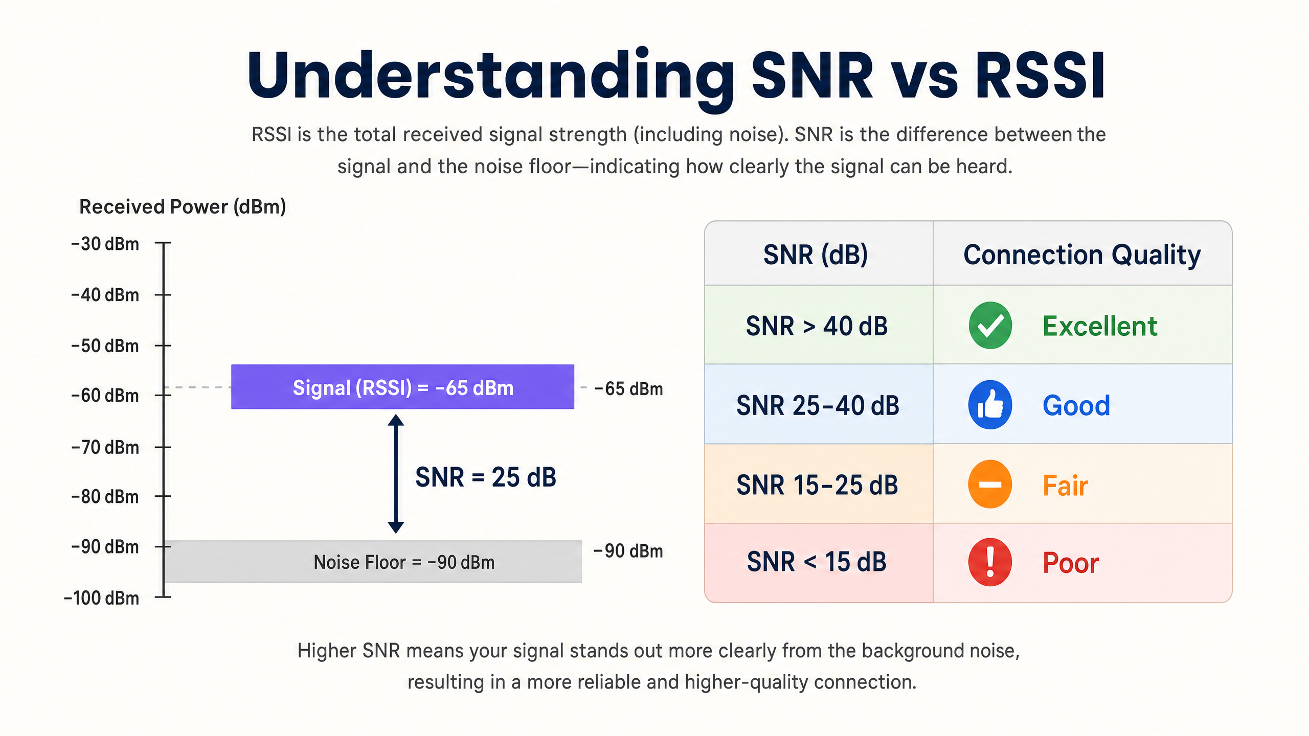
RSSI da solo è insufficiente per valutare la qualità della rete. Il Rapporto Segnale/Rumore (SNR) fornisce un quadro più accurato della qualità del collegamento confrontando la potenza del segnale ricevuto con il rumore di fondo ambientale. Un SNR di 25 dB o superiore è tipicamente richiesto per schemi di modulazione ad alta velocità come 256-QAM in 802.11ac/ax. Se il rumore di fondo è di -90 dBm e l'RSSI è di -65 dBm, l'SNR è di 25 dB — la soglia minima per un funzionamento affidabile ad alte prestazioni.
L'implicazione pratica è significativa: una rete può mostrare valori RSSI eccellenti su una heatmap di copertura ma funzionare male perché il rumore di fondo è elevato da fonti di interferenza non-Wi-Fi (forni a microonde, telefoni DECT, dispositivi Bluetooth o apparecchiature industriali). Strumentare sempre sia RSSI che SNR durante i sopralluoghi e il monitoraggio continuo.
La Fisica della Propagazione RF e dell'Attenuazione
In ambienti complessi come ospedali ( Sanità ) o hub di transito ( Trasporti ), i segnali RF subiscono attenuazione mentre attraversano ostacoli fisici. Gli architetti di rete devono tenere conto di queste perdite specifiche del materiale quando conducono sopralluoghi predittivi e definiscono i confini delle celle:
| Materiale | Attenuazione Tipica (dB) |
|---|---|
| Cartongesso / Intonaco | 3–4 dB |
| Vetro (standard) | 2–3 dB |
| Mattone | 8–12 dB |
| Cemento | 12–15 dB |
| Cemento Armato / Acciaio | 15–25+ dB |
| Scaffalature Metalliche (vendita al dettaglio) | 10–20 dB |
La natura logaritmica della scala dei decibel è fondamentale da interiorizzare: una perdita di 3 dB dimezza la potenza del segnale, mentre una perdita di 10 dB la riduce di un fattore dieci. Un segnale che attraversa due muri di mattoni (circa 20 dB di attenuazione) è quindi 100 volte più debole del segnale trasmesso.
Pianificazione dei Canali: CCI e ACI
La pianificazione ottimale dei canali richiede la mitigazione di due distinti tipi di interferenza. L'Interferenza Co-Canale (CCI) si verifica quando i punti di accesso che operano sullo stesso canale possono "sentirsi" a vicenda, portando a contese del mezzo e maggiore latenza a causa del protocollo CSMA/CA (Carrier-Sense Multiple Access with Collision Avoidance). Ogni dispositivo sul canale deve attendere il proprio turno, e quando più AP sono in contesa simultaneamente, l'utilizzo del canale aumenta anche con un carico client moderato.
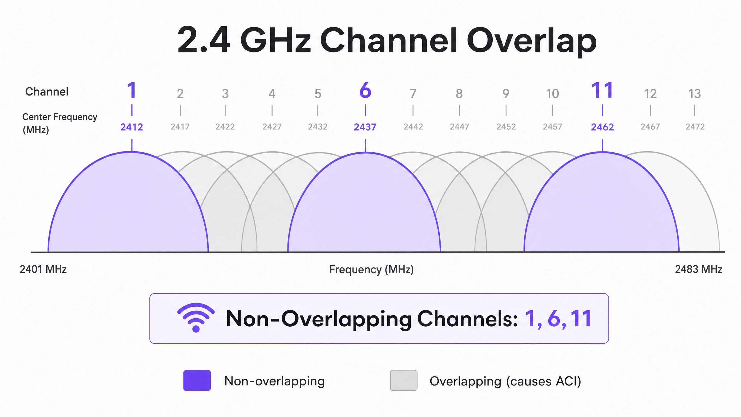
L'Interferenza del Canale Adiacente (ACI) si verifica quando gli AP operano su canali sovrapposti, aumentando il rumore di fondo e degradando l'SNR. Nella banda a 2.4 GHz, solo i canali 1, 6 e 11 non si sovrappongono. Qualsiasi altra assegnazione di canale causerà ACI con uno o entrambi i suoi vicini. Nella banda a 5 GHz, l'utilizzo dei canali Dynamic Frequency Selection (DFS) espande lo spettro disponibile, sebbene gli eventi di rilevamento radar possano forzare cambiamenti di canale, causando brevi interruzioni della connettività.
Quando si decide la larghezza dei canali, fare riferimento a 20MHz vs 40MHz vs 80MHz: Quale larghezza di canale dovresti usare? (o la versione italiana: 20MHz vs 40MHz vs 80MHz: Quale larghezza di canale dovresti usare? ). Il principio fondamentale: canali più ampi offrono un throughput teorico più elevato ma riducono il numero di opzioni non sovrapposte, aumentando la CCI in implementazioni dense.
Guida all'Implementazione
Fase 1: Definire i Requisiti e Identificare il Dispositivo LCMI
Prima di implementare l'hardware, definire l'Area di Copertura Primaria (PCA) e l'Area di Copertura Secondaria (SCA). È fondamentale identificare il dispositivo Meno Capace, Più Importante (LCMI) — il dispositivo con la radio più debole che deve assolutamente operare in modo affidabile. Si tratta spesso di uno scanner portatile legacy in un magazzino, di un modello specifico di dispositivo medico in un ospedale o di uno smartphone più vecchio in un ambiente ricettivo. Progettare l'intera architettura RF per soddisfare i requisiti RSSI minimi di tale dispositivo, e tutto il resto funzionerà meglio.
Fase 2: Condurre un'Indagine Attiva del Sito
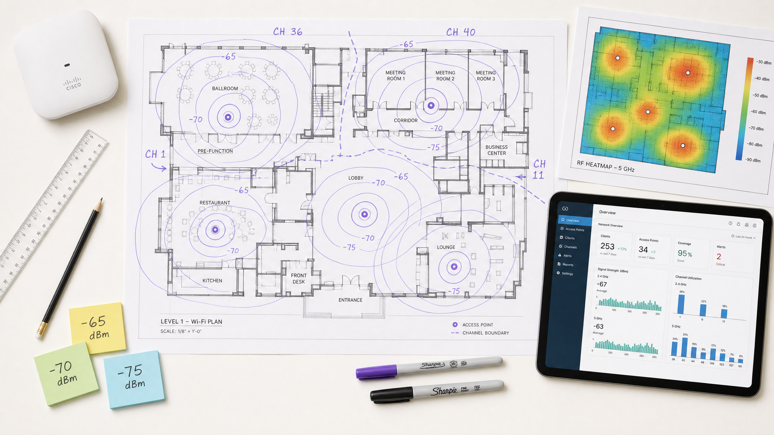
Eseguire un'indagine attiva del sito per misurare RSSI e SNR nel mondo reale — non solo un'indagine predittiva utilizzando software. Utilizzare strumenti di analisi dello spettro per identificare le sorgenti di interferenza non-Wi-Fi. Assicurarsi che la copertura primaria soddisfi la soglia di -65 dBm e la copertura secondaria (per le zone di sovrapposizione di roaming) soddisfi -70 dBm. Documentare il rumore di fondo in tutte le aree, poiché questo determinerà l'SNR raggiungibile e le massime velocità di trasmissione dati supportate.
Fase 3: Posizionamento degli AP e Regolazione della Potenza
Evitare l'errore del "più forte è meglio". Impostare la potenza di trasmissione dell'AP troppo alta crea collegamenti asimmetrici in cui il client può sentire chiaramente l'AP, ma l'AP non può ricevere in modo affidabile le trasmissioni più deboli del client. Questa è la causa principale del problema del client "appiccicoso" — dispositivi che rimangono associati a un AP distante nonostante siano fisicamente più vicini a un altro. Regolare la potenza di trasmissione dell'AP a 10–14 dBm per corrispondere alle capacità del client e assicurare una sovrapposizione delle celle del 15–20% per facilitare il roaming senza interruzioni secondo IEEE 802.11k/v/r.
Fase 4: Applicare Velocità di Trasmissione Dati Minime Obbligatorie
Disabilitare le velocità di trasmissione dati legacy (1, 2, 5.5 e 11 Mbps a 2.4 GHz; 6 e 9 Mbps a 5 GHz). Ciò eleva la soglia RSSI minima alla quale un client considera la connessione accettabile, forzando decisioni di roaming anticipate e impedendo ai client a bassa velocità di consumare una quantità sproporzionata di tempo di trasmissione.
Fase 5: Integrare Guest WiFi e Analisi
L'implementazione di una soluzione Guest WiFi aziendale richiede un'autenticazione senza interruzioni che non degradi l'esperienza utente. Implementare 802.1X per i dispositivi aziendali e Captive Portal sicuri per gli ospiti, con WPA3 dove la compatibilità del dispositivo lo consente. Approcci moderni come How a wi fi assistant Enables Passwordless Access in 2026 riducono l'attrito nell'onboarding mantenendo la conformità ai requisiti PCI DSS e GDPR. L'architettura RF descritta in questa guida è il prerequisito per analisi e servizi di localizzazione affidabili — se l'RF è mal progettata, i dati saranno inaccurati.
Migliori Pratiche
Progettare per la capacità, non per la copertura. Negli ambienti moderni ad alta densità, il vincolo non è quasi mai la portata del segnale — è la contesa del tempo di trasmissione. Implementare più AP con una potenza di trasmissione inferiore anziché meno AP con alta potenza. Ciò riduce la CCI, migliora l'SNR e aumenta il numero di client che possono essere serviti contemporaneamente.
Standardizzare le larghezze di canale per ambiente. Impostare come predefinito 20 MHz a 2.4 GHz universalmente. A 5 GHz, utilizzare 20 MHz in ambienti a densità molto alta (stadi, sale conferenze) e 40 MHz in ambienti a densità moderata (hotel, negozi). Riservare 80 MHz solo per scenari a bassa densità e alto throughput.
Implementare lo stack del protocollo di roaming. Abilitare 802.11k (Misurazione delle Risorse Radio), 802.11v (Gestione della Transizione BSS) e 802.11r (Transizione BSS Veloce) su tutti gli AP. Ciò garantisce che le decisioni di roaming siano guidate dalle condizioni RF piuttosto che dall'inerzia del client e riduce la latenza di riautenticazione da centinaia di millisecondi a meno di 50 ms.
Validare manualmente i canali assegnati automaticamente. La maggior parte dei fornitori di AP aziendali offre la gestione automatica delle risorse radio (RRM). Sebbene utile come base, l'RRM può prendere decisioni non ottimali in ambienti complessi. Verificare sempre il piano dei canali dopo l'implementazione e sovrascrivere dove necessario.
Monitorare continuamente, non solo al momento dell'implementazione. Gli ambienti RF cambiano nel tempo — appaiono nuove sorgenti di interferenza, i modelli di occupazione si spostano e gli aggiornamenti del firmware alterano il comportamento della radio. Utilizzare una piattaforma WiFi Analytics con monitoraggio RF continuo per rilevare il degrado prima che influisca sugli utenti.
Per strategie più ampie su come sfruttare l'infrastruttura di rete per i risultati aziendali, consultare Come Migliorare la Soddisfazione degli Ospiti: Il Playbook Definitivo .
Risoluzione dei Problemi e Mitigazione dei Rischi
Il Problema del Client "Appiccicoso"
Sintomo: I dispositivi rimangono connessi a un AP distante con un RSSI scarso (-80 dBm) nonostante siano fisicamente più vicini a un AP diverso con un segnale forte.
Causa Radice: La potenza di trasmissione dell'AP è troppo alta, creando un collegamento asimmetrico. Il client sente bene l'AP e non avvia un roaming. In alternativa, i protocolli 802.11k/v sono disabilitati, lasciando il client senza indicazioni su AP migliori disponibili.
Mitigazione: Abbassare la potenza di trasmissione dell'AP a 10–12 dBm. Abilitare 802.11k/v/r. Impostare velocità di trasmissione dati minime obbligatorie per forzare i client a effettuare il roaming quando l'RSSI degrada al di sotto della soglia di velocità minima.
Elevata Interferenza Co-Canale
Sintomo: Utilizzo del canale costantemente superiore al 40–50% anche con un carico client moderato, con conseguente latenza elevata e throughput scarso.
Causa Radice: Gli AP sullo stesso canale sono posizionati troppo vicini tra loro, o le larghezze di canale sono troppo ampie per la densità di implementazione.
Mitigazione: Ridurre la larghezza del canale a 20 MHz. Verificare il piano dei canali per massimizzare la separazione fisica tra gli AP sullo stesso canale. A 2.4 GHz, considerare disabilitando la radio su ogni altro AP in implementazioni molto dense.
Livello di Rumore Elevato
Sintomo: I valori RSSI appaiono accettabili sulle mappe di calore, ma il throughput è scarso e le connessioni sono instabili.
Causa Radice: Fonti di interferenza non-Wi-Fi (forni a microonde, telefoni DECT, apparecchiature industriali, Bluetooth) stanno innalzando il livello di rumore, degradando l'SNR al di sotto della soglia richiesta per la modulazione di ordine superiore.
Mitigazione: Utilizzare un analizzatore di spettro per identificare e caratterizzare le fonti di interferenza. Migrare i client interessati a 5 GHz dove possibile, poiché la maggior parte delle interferenze non-Wi-Fi è concentrata a 2.4 GHz. Se le fonti di interferenza non possono essere eliminate, aumentare la densità degli AP per migliorare l'RSSI e mantenere così un SNR adeguato nonostante il livello di rumore elevato.
Man mano che le reti si espandono in spazi municipali e pubblici, la pianificazione strategica diventa sempre più critica. Per approfondimenti sulle implementazioni nel settore pubblico, leggi come Purple Appoints Iain Fox as VP Growth – Public Sector to Drive Digital Inclusion and Smart City Innovation .
ROI e Impatto sul Business
L'ottimizzazione dell'RSSI e della pianificazione dei canali incide direttamente sui risultati economici su più dimensioni. La seguente tabella riassume i principali risultati di business associati a una rete wireless ben architettata:
| Risultato di Business | Meccanismo | Impatto Tipico |
|---|---|---|
| Costi di supporto IT ridotti | Meno reclami di connettività; meno visite in loco | Riduzione del 20–40% dei ticket di supporto relativi al Wi-Fi |
| Migliore soddisfazione degli ospiti | Connettività affidabile e ad alta velocità in tutta la sede | Miglioramento misurabile del NPS e dei punteggi delle recensioni |
| Analisi della posizione accurate | Densità AP e SNR sufficienti per una trilaterazione affidabile | Precisione della posizione inferiore a 3 metri per l'analisi del flusso di visitatori |
| Acquisizione di dati di prima parte | Prestazioni affidabili del Captive Portal | Tassi di completamento più elevati nell'onboarding del guest Wi-Fi |
| Efficienza operativa | Connettività affidabile per dispositivi portatili, sistemi POS, IoT | Riduzione dei fallimenti delle transazioni e dei tempi di inattività operativi |
Per gli operatori di sedi, il Wi-Fi affidabile non è più un centro di costo ma un abilitatore di entrate. Assicurando una potenza del segnale costante e un SNR elevato, le sedi possono implementare con fiducia i Captive Portal per acquisire dati di prima parte, guidando campagne di marketing personalizzate e aumentando il valore a vita del cliente. L'investimento in una corretta progettazione RF produce un ROI misurabile attraverso l'efficienza operativa, un maggiore coinvolgimento digitale e la capacità di implementare con fiducia analisi avanzate e servizi di localizzazione.
La piattaforma hardware-agnostic di Purple si integra con l'infrastruttura esistente per fornire il livello di analisi su una base RF ben progettata — trasformando i dati sulla potenza del segnale in business intelligence utilizzabile in ambienti Hospitality , Retail , Healthcare e Transport .
Definizioni chiave
RSSI (Received Signal Strength Indicator)
A relative measurement of the power level of an RF signal received by a client device, expressed in negative dBm. The closer to zero, the stronger the signal.
Used to determine coverage boundaries, trigger roaming decisions, and assess basic signal availability. Not sufficient on its own to evaluate link quality.
SNR (Signal-to-Noise Ratio)
The difference in decibels (dB) between the received signal strength and the ambient noise floor. Calculated as: SNR (dB) = RSSI (dBm) − Noise Floor (dBm).
The primary determinant of achievable modulation scheme and data rate. An SNR of 25 dB is the minimum for 256-QAM (high-throughput) operation. Always measure alongside RSSI.
CCI (Co-Channel Interference)
Interference that occurs when multiple APs and clients operate on the same channel and can detect each other's transmissions, causing medium contention under the CSMA/CA protocol.
The most common cause of high channel utilisation and latency in enterprise deployments. Mitigated by proper channel planning, power tuning, and ensuring adequate physical separation between APs on the same channel.
ACI (Adjacent Channel Interference)
Interference caused by RF energy from one channel bleeding into an adjacent overlapping channel, raising the noise floor and degrading SNR.
Caused by using overlapping channels in the 2.4 GHz band (anything other than 1, 6, 11). Avoided by strict adherence to non-overlapping channel assignments.
DFS (Dynamic Frequency Selection)
A regulatory mechanism that allows Wi-Fi devices to share the 5 GHz spectrum with radar systems by monitoring for radar signals and vacating the channel if detected.
Expands the available 5 GHz channel set, but requires APs to change channels upon radar detection, causing a brief connectivity disruption. Must be accounted for in deployments near airports, military installations, or weather radar sites.
CSMA/CA (Carrier-Sense Multiple Access with Collision Avoidance)
The medium access protocol used by Wi-Fi, in which devices listen to the RF channel before transmitting and defer if the channel is busy.
The fundamental reason Wi-Fi is a half-duplex, shared medium. CCI forces multiple APs and clients to contend for the same channel, which is why channel planning is critical to performance.
Sticky Client
A client device that remains associated with an AP delivering a weak signal despite being physically closer to a different AP with a stronger signal.
Caused by asymmetric link budgets (AP transmit power too high) or absence of 802.11k/v roaming protocols. Results in poor throughput, high latency, and degraded user experience.
LCMI (Least Capable, Most Important) Device
The device in a deployment with the weakest radio capabilities that is nonetheless critical to business operations.
Used as the design baseline for RF architecture. Designing to meet the LCMI device's requirements ensures all other devices perform adequately.
802.11k/v/r
A suite of IEEE 802.11 amendments: 802.11k (Radio Resource Measurement), 802.11v (BSS Transition Management), and 802.11r (Fast BSS Transition).
Together, these protocols enable intelligent, low-latency client roaming. 802.11k provides neighbour reports, 802.11v enables network-directed roaming, and 802.11r reduces re-authentication time to under 50 ms.
Esempi pratici
A 300-room hotel is experiencing poor Wi-Fi performance in guest rooms despite having an AP in every corridor. Guests report dropped connections and slow speeds, particularly in rooms furthest from the corridor APs. The existing APs are configured at maximum transmit power (23 dBm) on auto channel assignment.
The root cause is a combination of Co-Channel Interference (CCI) from corridor APs hearing each other down the long hallways, signal attenuation through guest room doors and walls, and the sticky client problem caused by excessively high transmit power. The recommended solution is to transition to an in-room AP deployment model using wall-plate APs (e.g., Cisco Catalyst 9105AXW or Aruba AP-303H). Configure each AP with a transmit power of 10–12 dBm. Disable 2.4 GHz on every other AP in the corridor to reduce CCI. Standardise on 20 MHz channels in 5 GHz with a manual channel plan assigning channels 36, 40, 44, 48, 52, 56, 60, 64 in a repeating pattern. Enable 802.11k/v/r on all APs. Set minimum mandatory data rates to 12 Mbps in 2.4 GHz and 24 Mbps in 5 GHz. Validate with a post-deployment active site survey targeting -65 dBm RSSI and 25 dB SNR in all guest rooms.
A large retail chain operating 50,000 sq ft stores wants to deploy Wi-Fi location analytics to track customer footfall and dwell time by department. Initial data from the existing network shows location accuracy of ±15 metres, which is insufficient for department-level analysis. The existing infrastructure has APs mounted at 6-metre intervals along the central spine of the store.
Location analytics based on RSSI trilateration require a minimum of three APs to hear a client device simultaneously, with each AP receiving a signal of -75 dBm or better. The current linear AP layout means that in the outer departments, clients are only within range of one or two APs, making accurate trilateration impossible. The solution requires a redesigned AP layout using a staggered grid pattern with APs at the perimeter and interior of each department zone, ensuring that any point on the floor is within -75 dBm range of at least three APs. Reduce AP transmit power to 10 dBm to tighten RF cells and improve the differential between AP readings (which is what drives location accuracy). Enable 802.11k/v to ensure devices don't stick to distant APs, which skews location data. Integrate the AP infrastructure with Purple's WiFi Analytics platform to process RSSI data into footfall heatmaps and dwell time reports by department.
Domande di esercitazione
Q1. You are designing a Wi-Fi network for a 40,000-seat stadium. The venue operator wants maximum throughput for concurrent video streaming and social media uploads during events. You are considering using 80 MHz channels in the 5 GHz band to maximise per-client throughput. Is this the recommended approach, and what channel plan would you implement instead?
Suggerimento: Consider the number of non-overlapping 80 MHz channels available in the 5 GHz band versus 20 MHz channels, and the impact of Co-Channel Interference in an open, high-density environment.
Visualizza risposta modello
No. Using 80 MHz channels in a stadium is strongly contraindicated. In the standard 5 GHz UNII-1/2/2e bands, there are only a handful of non-overlapping 80 MHz channels, meaning that with the AP density required for 40,000 concurrent users, severe CCI is inevitable. The correct approach is to use 20 MHz channels throughout, which provides up to 24 non-overlapping channels in 5 GHz (including DFS), maximising channel reuse. Directional sector antennas should be used to tightly control RF cell coverage, pointing down into seating sections rather than radiating omnidirectionally. AP density should be calculated based on a target of no more than 30–50 clients per AP radio, with transmit power tuned to match the coverage area of each sector.
Q2. A warehouse deployment uses handheld barcode scanners that frequently drop connections when operators move between aisles. The APs are configured at maximum transmit power (23 dBm) to ensure full coverage. The scanners run a legacy WMS application that requires sub-100ms latency. What is the likely cause and what steps would you take to resolve it?
Suggerimento: Consider the transmit power capabilities of a small handheld scanner versus an enterprise AP, and the implications for the link budget in both directions.
Visualizza risposta modello
The likely cause is the sticky client problem resulting from an asymmetric link budget. The APs are transmitting at 23 dBm, so the scanners hear them well across the entire warehouse and do not initiate a roam. However, the scanners' internal radios typically transmit at only 15–17 dBm, meaning the AP cannot reliably receive the scanner's transmissions when it is far away. The solution is to lower AP transmit power to 10–12 dBm to match the scanners' capabilities, ensuring that the coverage cells are appropriately sized and that scanners roam when they move out of range. Enable 802.11k/v/r to facilitate fast roaming. Set minimum mandatory data rates to 12 Mbps to force earlier roaming decisions. Validate with an active site survey using the actual scanner hardware to confirm -65 dBm RSSI and 25 dB SNR throughout all aisles.
Q3. During a site survey for a new hospital wing, you measure an RSSI of -58 dBm from the primary AP throughout the target area. However, the noise floor measured by a spectrum analyser is consistently -72 dBm due to legacy medical monitoring equipment operating in the 2.4 GHz band. The hospital requires reliable VoWiFi for clinical communications. Will this network support VoWiFi, and what actions would you recommend?
Suggerimento: Calculate the SNR and evaluate it against the minimum requirement for VoWiFi. Consider which frequency band is affected and what mitigation options are available.
Visualizza risposta modello
No, this network will not reliably support VoWiFi in its current state. The SNR is calculated as -58 dBm - (-72 dBm) = 14 dB. This falls below the minimum 20 dB SNR required for VoWiFi and well below the 25 dB target for high-quality voice. Despite the strong RSSI of -58 dBm, the elevated noise floor from the medical equipment degrades the link quality to an unacceptable level. Recommended actions: First, migrate VoWiFi traffic to the 5 GHz band, which is largely unaffected by the legacy 2.4 GHz medical equipment. Second, increase AP density in the affected areas to improve RSSI to -50 dBm or better, which would yield an SNR of 22 dB even with the elevated noise floor — marginally acceptable for VoWiFi. Third, engage the biomedical engineering team to assess whether the legacy equipment can be replaced or shielded. Fourth, implement QoS (WMM) with voice traffic prioritisation to protect VoWiFi traffic from competing with data traffic during periods of congestion.