Top 10 Causes of DHCP Timeouts on High-Density Wireless Networks
This authoritative technical reference guide identifies the top ten causes of DHCP timeouts on high-density wireless networks and provides actionable, vendor-neutral remediation strategies. Designed for senior IT leaders, network architects, and venue operations directors, it covers deep-dive engineering principles, step-by-step implementation workflows, and measurable business outcomes. Learn how to eliminate connection bottlenecks and optimize your wireless infrastructure to deliver seamless connectivity in demanding enterprise environments.
Listen to this guide
View podcast transcript
執行摘要
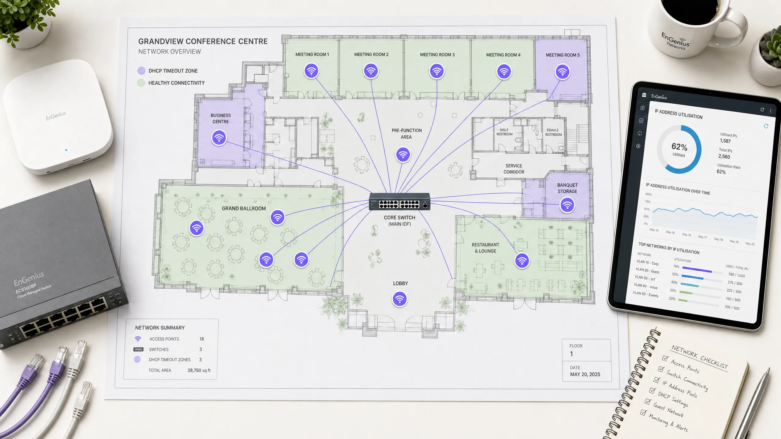
在現代企業環境中(例如高容量的飯店、零售商場、交通樞紐和體育場館),無線連線是推動業務發展的關鍵基石。然而,顧客體驗往往在網路初始上網的第一步就宣告失敗:獲取 IP 位址。在高密度無線網路上,動態主機設定協定(DHCP)逾時是上網失敗最常見卻也最常被誤診的根本原因之一。當數百或數千台裝置同時嘗試連線時,傳統的 DHCP 設定在如此高負載下會崩潰,導致使用者卡在旋轉的載入畫面,或只能取得自行分配的 169.254.x.x 連結本地位址。
本權威技術參考指南深入探討了高密度無線網路上導致 DHCP 逾時的前十大原因。它跳過學術理論,直接為資深網路架構師、CTO 和場館營運總監提供即時、可執行的改善策略。透過系統化地優化 DHCP 領域大小、縮短租約時間、實施強健的 Layer 2/3 設定以及部署高可用性伺服器架構,企業可以顯著降低連線延遲、消除上網阻礙並保護其品牌聲譽。實施這些最佳實踐與提升顧客滿意度、提高對 Guest WiFi 等核心產品的參與度,以及透過 WiFi Analytics 獲取更豐富的數據直接相關。
技術深度剖析
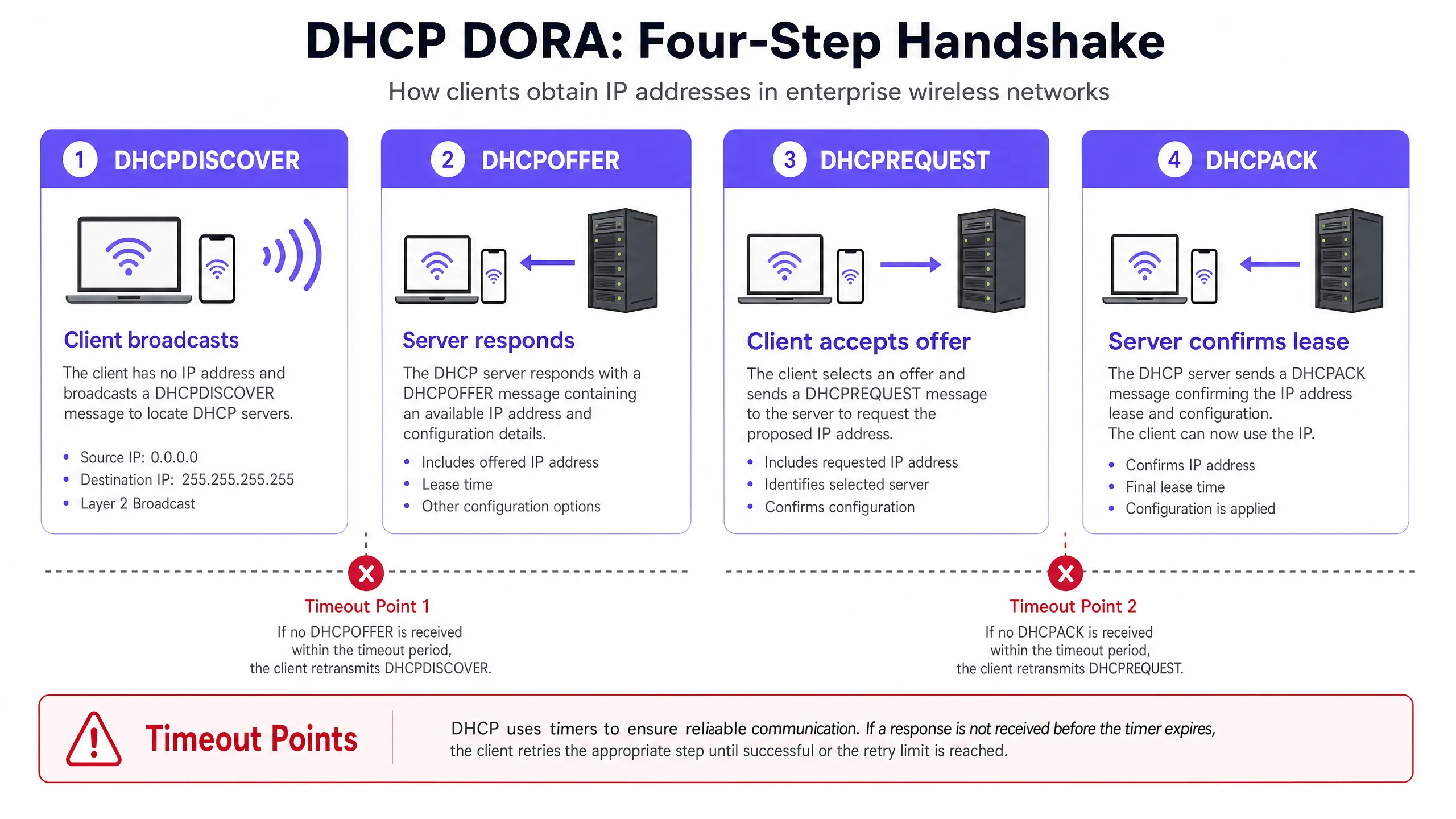
要診斷並解決 DHCP 逾時問題,網路工程師必須首先了解四向 DHCP 握手(通常稱為 DORA 流程:Discover、Offer、Request、Acknowledge)的精確運作機制 [1]。在高密度環境中,此流程對封包遺失、延遲和資源耗盡極為敏感。
高密度無線網路中的 DHCP 握手(DORA)
- DHCPDISCOVER(廣播):無線用戶端與基地台(AP)建立關聯,並廣播一個封包以尋找可用的 DHCP 伺服器。在大型廣播網域中,此封包會充斥於所有連接埠,消耗寶貴的無線空中時間。
- DHCPOFFER(單播/廣播):收到 discover 訊息的每個作用中 DHCP 伺服器都會保留一個 IP 位址,並向用戶端發送 offer,其中指定了租約參數、子網路遮罩、預設閘道器和 DNS 伺服器。
- DHCPREQUEST(廣播):用戶端選擇其中一個 offer(通常是第一個收到的),並廣播一個 request 以接受該特定 IP 位址,這也隱含拒絕了其他所有 offer。
- DHCPACK (單播/廣播):選定的 DHCP 伺服器將租約寫入其資料庫,並向用戶端發送確認訊息,確認 IP 分配和租約期限。用戶端隨後套用此設定。
無線開銷與空口時間擁塞的影響
有線網路是以千兆速度在硬體層面處理 Layer 2 廣播,但無線網路不同,它會以最低強制資料速率(通常為 1 Mbps、6 Mbps 或 11 Mbps,具體取決於 SSID 設定)傳輸廣播和多播訊框,以確保所有遠端用戶端都能接收 [2]。在擁有數千台活動裝置的高密度 SSID 上,廣播 DHCP 封包會消耗不成比例的射頻空口時間,導致封包衝突、重傳並最終逾時。用戶端裝置通常預期在 2 到 4 秒內收到 DHCP 回應;如果空口時間擁塞將 DORA 流程的任何步驟延遲到此視窗之外,用戶端就會逾時、中斷關聯並重試,從而對網路造成連鎖負載。
DHCP 逾時的 10 大原因
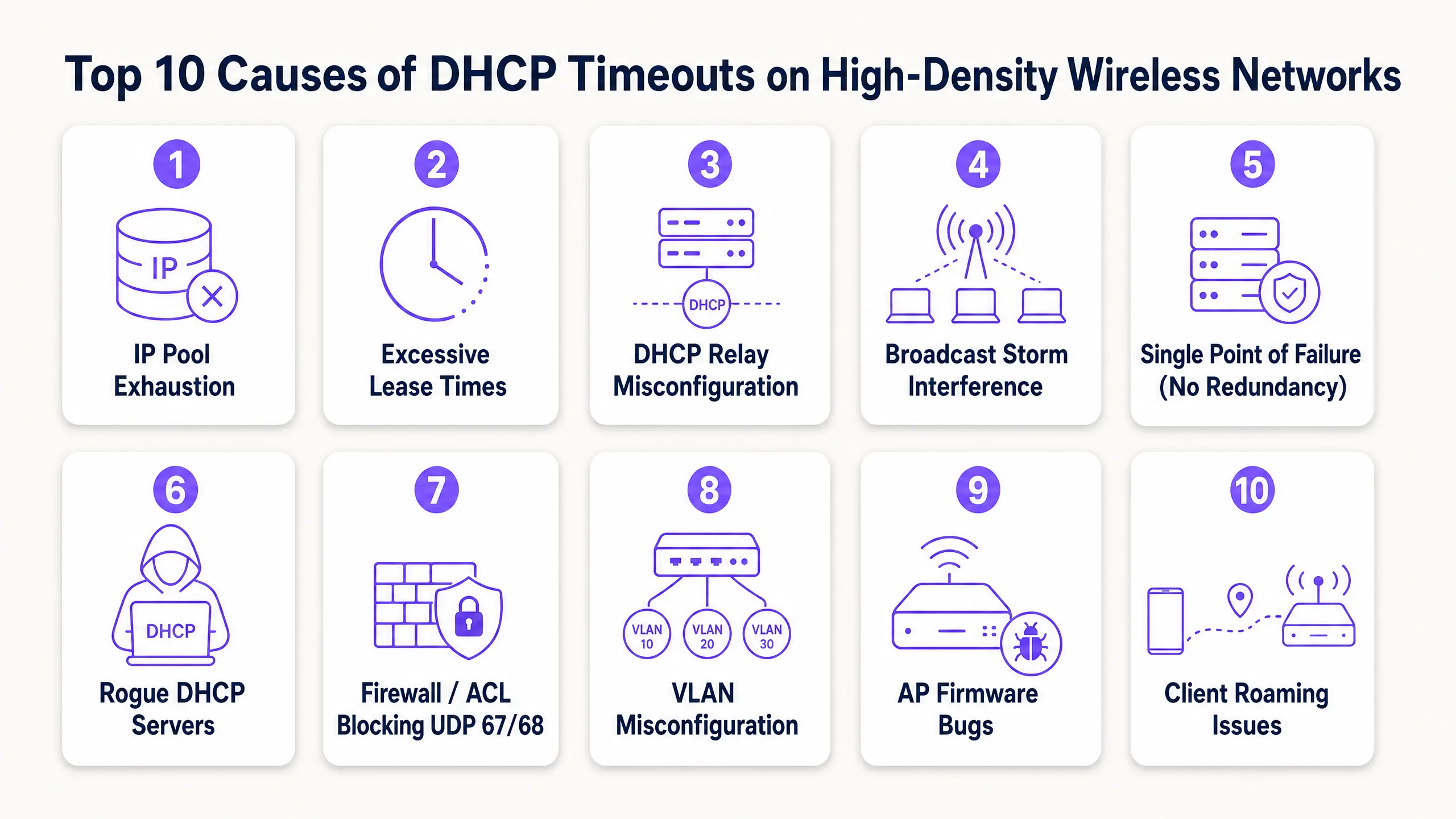
1. DHCP IP 位址池耗盡
機制:DHCP 伺服器的範圍對於暫時性裝置的數量而言太小。當位址池使用率達到 100% 時,伺服器會直接忽略新的 DHCPDISCOVER 封包,因為它沒有可提供的位址。
高密度場景:標準的 Class C 子網路(/24)僅提供 254 個可用 IP 位址。在飯店大廳、體育場入口或會議主會場,同時連線的裝置數量很容易在幾分鐘內超過此限制。更嚴重的是,許多使用者攜帶多個連網裝置(手機、智慧手錶、平板電腦、筆記型電腦),使 IP 需求倍增。
解決方案:使用無類別域間路由(CIDR)標記法來調整網路範圍。將高密度用戶端 VLAN 轉換為 /22(1,022 個 IP)或 /21(2,046 個 IP)子網路。確保您的監控工具設定為在位址池使用率達到 80% 時發出警報,以便在高峰活動前主動擴展範圍。
2. 訪客網路上的租約時間過長
機制:租約時間決定了用戶端在必須更新或釋放 IP 位址之前可以保留該位址多久。如果租約時間過長,DHCP 伺服器會將該位址保留在資料庫中,即使原始裝置已離開場地,也無法將其重新分配給新用戶端。
高密度場景:許多預設的 DHCP 設定指定了 24 小時或 8 天的租約時間。在人員流動率高的公共場所或餐旅環境中(例如交通轉運站或購物中心),訪客通常停留不超過兩小時 [3]。在 24 小時租約的情況下,連線 10 分鐘的訪客會佔用一個 IP 位址一整天,從而導致人為的位址池耗盡。 補救措施:將租約時間與用戶端停留時間保持一致。針對訪客網路實施 30 至 60 分鐘的租約時間。對於裝置在整個班次期間都保持連線的企業員工網路,則使用 8 至 12 小時的租約時間。這可確保快速回收已離開用戶端的 IP 位址。
3. DHCP 中繼代理程式(Relay Agent)設定錯誤
運作機制:由於 DHCP 探索訊息屬於 Layer 2 廣播,因此無法跨越路由器(Layer 3)邊界。DHCP 中繼代理程式(通常在 Layer 3 交換器或安全閘道器上使用類似 Cisco 的 ip helper-address 指令進行設定)必須攔截這些廣播,並將其作為單播封包轉發給中央 DHCP 伺服器 [4]。如果中繼代理程式設定錯誤、Helper IP 不正確,或在新建的 VLAN 中遺漏了該代理程式,DHCP 流量將會被阻擋。
高密度環境背景:高密度網路極度依賴 VLAN 切割來限制廣播網域。在部署新 SSID 或擴大場地時,工程師通常會建立新的用戶端 VLAN。如果對應的 Layer 3 介面上未更新中繼代理程式設定,這些 VLAN 上的用戶端將會立即遇到 DHCP 逾時。
補救措施:為所有 Layer 3 交換器建立嚴格的設定範本。確保每個用戶端 VLAN 介面都有一對備援的 DHCP Helper 位址,指向您的主要和次要 DHCP 伺服器。驗證中繼介面 IP(DHCP 伺服器用來確定要分配哪個子網路範圍)與 DHCP 伺服器本身之間的端到端路由。
4. 廣播與多播風暴
運作機制:VLAN 上過多的廣播或多播流量會使無線介質飽和。由於無線網路是共享的半雙工介質,AP 和用戶端在傳輸前必須等待空中通道空閒。廣播風暴(通常由交換迴圈、故障的網路卡或具侵略性的點對點協定引起)會佔滿空中時間,導致 DHCP 封包被排隊、延遲或丟棄。
高密度環境背景:在沒有適當 Layer 2 隔離的大型扁平無線網路中,點對點廣播流量(例如 Apple AirPlay、Google Chromecast 或 Windows 網路探索)會被 VLAN 上的每個 AP 複製。在擁有 10,000 名使用者的場地中,這種背景「雜音」可能會消耗超過 50% 的可用無線頻寬,導致關鍵的 DHCP 握手封包沒有足夠的空中時間進行傳輸。
補救措施:在無線控制器上啟用用戶端隔離(Client Isolation,也稱為點對點阻擋),以防止用戶端之間直接通訊。在 AP 和交換器上設定廣播與多播抑制,將廣播流量限制在鏈路容量的一小部分(例如每秒 100 個封包)。在支援的情況下,在 AP 上啟用 DHCP Proxy,將廣播的 DHCP Offer 和 Acknowledgement 轉換為專門針對請求用戶端的單播訊框。
5. 單一故障點(缺乏 DHCP 備援)
機制:單一、無備援的 DHCP 伺服器代表著關鍵的脆弱性。如果該伺服器當機、進行系統更新或失去網路連線,整個網路的用戶上線能力將立即中斷。現有的租約仍保持作用,但新用戶端無法取得 IP 位址,且漫遊用戶端也無法更新其租約。
高密度情境:高密度場域在嚴格的營運 SLA 下運作。比賽期間的體育場或進行主題演講的會議中心,連五分鐘的 DHCP 停機時間都無法容忍。依賴單一路由器或單一虛擬機器來處理數千個快速的租約請求,是一種高風險的架構。
解決方案:以高可用性配置部署 DHCP。在負載平衡模式(50/50 分流)或熱備援模式下使用 Windows Server DHCP Failover,或部署備援的企業級 DHCP 設備(例如 Infoblox 或 BlueCat)[5]。確保您的 DHCP 伺服器在物理或邏輯上分散在不同的虛擬化管理程序(hypervisors)和網路路徑中,以消除共模故障。
6. 惡意 DHCP 伺服器
機制:惡意 DHCP 伺服器是指連接到網路的未授權、已啟用 DHCP 的裝置。它會攔截用戶端的 DHCPDISCOVER 廣播,並以其自身的 DHCPOFFER 封包進行回應,通常會發送錯誤的 IP 配置、錯誤的預設閘道或惡意的 DNS 伺服器。
高密度情境:在大型場館、零售店面或公共部門辦公室中,實體乙太網路連接埠通常暴露在公共區域,或者使用者可能會攜帶未授權的裝置(例如消費級旅行路由器或執行橋接網路的虛擬機器)並將其插到牆上插座。這會導致 IP 位址衝突、路由黑洞以及嚴重的安全性風險(包括中間人攻擊)。
解決方案:在所有存取和分發交換器上啟用 DHCP Snooping [6]。DHCP snooping 將交換器連接埠指定為「受信任」(連接到合法的 DHCP 伺服器或中繼代理)或「不受信任」(連接到用戶端)。交換器會自動丟棄來自不受信任連接埠的任何 DHCP 伺服器回應(例如 DHCPOFFER 或 DHCPACK),從而立即瓦解惡意伺服器。
7. 防火牆、ACL 和阻擋 UDP 67/68 的安全性原則
機制:DHCP 依賴 UDP 連接埠 67(伺服器端監聽和用戶端目的地)和 UDP 連接埠 68(用戶端監聽和伺服器端目的地)。如果網路防火牆、交換器存取控制清單 (ACL) 或端點安全性原則阻擋了這些連接埠,DORA 握手程序將無法完成。
高密度環境背景:安全性強化是企業網路的首要任務。然而,過於激進的安全策略往往會無意中阻擋 DHCP 流量。例如,在進行防火牆移轉或策略更新期間,管理員可能會阻擋某個網段上的所有 UDP 流量,卻未意識到他們已經中斷了 DHCP 路徑。同樣地,訪客 VLAN 安全策略在將流量重導向至 Captive Portal 之前,必須明確允許 UDP 67 和 68。
補救措施:稽核無線用戶端、AP、Layer 3 交換器和 DHCP 伺服器之間路徑上的所有 ACL 和防火牆規則。確保雙向皆明確允許 UDP 連接埠 67 和 68。進行疑難排解時,請在 DHCP 伺服器的網路介面進行封包擷取,以確認 DHCPDISCOVER 封包確實有送達。
8. VLAN 與 Trunking 設定錯誤
運作機制:如果用戶端的 SSID 對應到特定的 VLAN,但該 VLAN 在整個交換器基礎架構中未被正確標記(tagged)或建立 Trunk 連結,則用戶端的 DHCP 廣播將永遠無法到達預設閘道或 DHCP 中繼代理程式。
高密度環境背景:高密度無線網路使用動態 VLAN 分配或多 VLAN 資源池來分流用戶端負載。如果從 AP 到核心交換器路徑上的單一交換器 Trunk 連接埠在其允許清單中遺漏了某個 VLAN 標記,則用戶端子集(特別是被分配到該 VLAN 的用戶端)將會立即且持續遇到 DHCP 逾時,而同一 SSID 上的其他用戶端卻能成功連線。這會造成極度斷續、難以診斷的疑難排解情境。
補救措施:導入自動化網路設定管理與驗證工具。設定交換器 Trunk 連接埠時,請務必使用明確的允許清單(例如 switchport trunk allowed vlan 10,20,30),而不是依賴預設的「全部」設定,並驗證 Trunk 連結兩端的 Native VLAN 是否相符,以防止未標記的流量外洩。
9. 存取點(Access Point)韌體與驅動程式錯誤
運作機制:存取點韌體負責將 802.11 無線訊框橋接至 802.3 有線乙太網路。AP 無線驅動程式或橋接引擎中的軟體錯誤(Bug)可能會導致 AP 丟棄 DHCP 封包,特別是在高 CPU 或記憶體負載下。
高密度環境背景:高密度網路會將 AP 硬體和軟體推向極限。在 10 個用戶端的輕度負載下保持休眠的錯誤,當 AP 處理 100 個並行作用中用戶端時,可能會引發災難性的故障。例如,2026 年初在某些 WiFi 7 AP 上記錄到的一個已知錯誤,會導致 AP 斷續丟棄三次握手的第三個封包(DHCPREQUEST),使用戶端永遠無法收到其 DHCPACK 並完成上線流程。
補救措施:針對 AP 韌體維持嚴格的生命週期管理政策。避免將「最新、未經充分測試」的韌體版本直接部署到生產環境。建立一個模擬高密度環境的測試環境,並密切關注廠商的發行說明和社群論壇,以掌握已知的 DHCP 相關錯誤。如果排障過程中發現用戶端已發送 DHCPDISCOVER 封包,但 AP 的有線上行連接埠卻從未收到,則應懷疑是 AP 橋接錯誤。
10. 頻繁的用戶端漫遊與 Layer 3 邊界
機制:當無線用戶端從一個 AP 移動(漫遊)到另一個 AP 時,必須維持其網路工作階段。如果漫遊跨越了 Layer 3 邊界(將用戶端移至不同的子網路),用戶端必須取得新的 IP 位址。如果用戶端的作業系統或無線網路無法順暢處理此轉換,用戶端將會嘗試在新的子網路中使用舊的 IP 位址,進而導致連線逾時和 DHCP 重新協商失敗。
高密度情境:高密度場域需要數百個 AP 才能提供足夠的覆蓋範圍。用戶端處於持續移動的狀態——例如,飯店房客從客房走向會議廳,或零售商場中的顧客四處走動 [7]。如果網路架構將場域的不同實體區域對應到不同的子網路,將會產生大量的 Layer 3 漫遊,進而以頻繁的釋放(release)和請求(request)事件使 DHCP 伺服器過載。
補救措施:在整個用戶端 SSID 採用扁平化 Layer 2 架構來設計高密度無線網路,或實作基於無線控制器的通道技術(例如 GRE 或 CAPWAP)[8]。通道技術可確保用戶端的流量始終錨定回其原始的主控制器和 VLAN,無論其漫遊到哪個實體 AP,從而完全消除 Layer 3 漫遊事件及相關的 DHCP 開銷。
實作指南
若要系統性地消除 DHCP 逾時,網路架構師必須從被動排障轉變為主動、標準化的架構。請遵循此逐步部署指南來強化您的 DHCP 基礎架構。
步驟 1:子網路規劃與 CIDR 架構
切勿在高密度訪客網路中使用標準的 /24 子網路。請根據尖峰容量加上 50% 的緩衝來計算您的 IP 需求,以容納擁有多個裝置的用戶和暫時性的人流變動。
| 子網路遮罩 | CIDR | 可用 IP 位址 | 最佳使用案例 |
|---|---|---|---|
255.255.255.0 |
/24 |
254 | 行政人員、印表機、後勤 IoT |
255.255.254.0 |
/23 |
510 | 小型精品飯店、局部零售店面 |
255.255.252.0 |
/22 |
1,022 | 大型飯店、高密度會議室、學校校園 |
255.255.248.0 |
/21 |
2,046 | 大型展覽館、購物中心、公共廣場 |
255.255.240.0 |
/20 |
4,094 | 體育館、競技場、大型會議中心 |
步驟 2:最佳化 DHCP 租期
根據特定網路區段的使用者行為,設定您的 DHCP 伺服器以強制執行租期時間:
訪客 WiFi SSID (高流動率)     -> 租期時間:30 到 60 分鐘
企業員工 SSID (穩定)    -> 租期時間:8 到 12 小時
場域 IoT 與基礎設施       -> 租期時間:7 天 (或靜態保留)
注意:縮短租期時間會增加 DHCP 更新請求的頻率 (發生在租期時間的 50%,稱為 T1) [9]。請確保您的 DHCP 伺服器硬體具有足夠的 CPU 和 I/O 效能,以處理提升的請求率。
步驟 3:在 Layer 3 交換器上設定 DHCP 中繼代理 (Relay Agents)
設定 DHCP 中繼代理時,請務必指定指向獨立 DHCP 伺服器的備援協助器位址 (helper addresses)。以下是 Cisco iOS Layer 3 交換器介面的標準、與廠商無關的設定範本:
interface Vlan30
 description High_Density_Guest_WiFi
 ip address 192.168.30.1 255.255.252.0
 ip helper-address 10.10.10.10  # 主要 DHCP 伺服器
 ip helper-address 10.10.10.11  # 次要 DHCP 伺服器
 ip dhcp relay information option  # 插入 Option 82 以進行位置追蹤
 no shutdown
步驟 4:使用 DHCP 監聽 (Snooping) 強化 Layer 2 安全性
透過在整個交換器架構中啟用 DHCP 監聽,防止惡意 DHCP 伺服器並減輕 DHCP 耗盡攻擊。以下是邊緣存取交換器的設定範本:
# 全域啟用 DHCP 監聽
ip dhcp snooping

# 針對特定用戶端 VLAN 啟用 DHCP 監聽
ip dhcp snooping vlan 10,20,30

# 將連接到核心交換器/DHCP 伺服器的上行連接埠設定為「信任 (TRUSTED)」
interface GigabitEthernet1/0/48
 description UPLINK_TO_CORE
 ip dhcp snooping trust

# 將面向用戶端的連接埠設定為「非信任 (UNTRUSTED)」,並限制 DHCP 封包速率以防止耗盡攻擊
interface range GigabitEthernet1/0/1 - 47
 description CLIENT_ACCESS_PORTS
 ip dhcp snooping limit rate 15
最佳實踐
為了維持具備彈性且高效能的無線網路,請將這些業界標準的最佳實踐納入您的營運手冊中:
1. 實作 DHCP Option 82 (中繼代理資訊選項)
DHCP Option 82 允許中繼代理在將 DHCP 請求轉發到伺服器之前,將特定線路資訊 (例如交換器連接埠 ID 或 AP MAC 位址) 插入其中 [10]。這使 DHCP 伺服器能夠根據用戶端在場域內的實體位置,執行高度精細的 IP 分配原則。例如,飯店可以為會議中心的用戶端與客房內的用戶端分配不同的 IP 位址池或 DNS 設定,從而最佳化位址池的利用率。
2. 啟用 ARP 與 DHCP 廣播轉單播 (Broadcast-to-Unicast) 轉換
設定您的無線區域網路控制器 (WLC) 或雲端管理 AP,以攔截 Layer 2 廣播 ARP 和 DHCP 封包,並在透過無線電傳輸之前將其轉換為單播(unicast)訊框。由於單播訊框是以用戶端支援的最大資料速率(而非最低強制廣播速率)進行傳輸,因此這項簡單的設定變更可大幅減少 RF 空中時間(airtime)消耗,並提高高密度環境中的 DHCP 可靠性。
3. 建立主動式 DHCP 監控與警報
不要等待使用者回報連線失敗。設定您的網路管理系統 (NMS) 或 DHCP 伺服器監控工具,以追蹤關鍵指標並觸發即時警報:
- 位址池利用率:在利用率達到 75% 時觸發警告警報,在 85% 時觸發緊急警報。
- DHCP 請求速率:監控請求是否突然激增,這可能表示存在廣播風暴、漫遊迴圈或 DHCP 耗盡攻擊。
- 租約到期分佈:確保租約順利到期,且資料庫正在主動回收 IP 位址。
疑難排解與風險緩釋
當懷疑發生 DHCP 逾時,請遵循此系統化診斷工作流程,以快速隔離故障點並將業務中斷降至最低。
[用戶端關聯至 AP]
        │
        ▼
[在用戶端擷取封包] ───► 是否傳送 DHCPDISCOVER?
        │                         ├── 否:用戶端作業系統/驅動程式問題。
        │                         └── 是
        ▼
[在交換器擷取封包] ───► DHCPDISCOVER 是否到達交換器?
        │                         ├── 否:AP 橋接/VLAN 標記問題。
        │                         └── 是
        ▼
[在伺服器擷取封包] ───► DHCPDISCOVER 是否到達伺服器?
        │                         ├── 否:中繼代理程式 (Relay Agent) / 路由 / 防火牆問題。
        │                         └── 是
        ▼
[檢查伺服器記錄] ───────────► 是否傳送 DHCPOFFER?
                                  ├── 否:位址池已耗盡 / 範圍未啟用。
                                  └── 是:回傳路徑受阻 (VLAN/路由)。
關鍵疑難排解指令
若要驗證實體網路設備上的 DHCP 狀態並診斷故障,請使用以下指令:
Cisco IOS (DHCP 伺服器或中繼)
# 檢視 DHCP 位址池利用率與可用位址
show ip dhcp pool

# 檢視作用中的 IP 位址繫結
show ip dhcp binding

# 監控 DHCP 伺服器統計資料 (discover、request、ack 計數)
show ip dhcp server statistics

# 檢視 DHCP 衝突資料庫 (因衝突而被標記為損壞的 IP)
show ip dhcp conflict
Linux (DHCP 伺服器或用戶端)
# 在 Linux 用戶端上檢視即時 DHCP 用戶端租約請求
sudo dhclient -v wlan0

# 在特定介面上擷取 DHCP 流量 (UDP 連接埠 67 和 68)
sudo tcpdump -i eth0 -n -vv 'udp and (port 67 or port 68)'

# 檢查 dnsmasq DHCP 租約資料庫
cat /var/lib/misc/dnsmasq.leases
Windows (DHCP 用戶端)
# 釋放目前的 IP 位址
ipconfig /release

# 重新取得 IP 位址(啟動新的 DHCP 握手)
ipconfig /renew
投資報酬率與業務影響
投資於高彈性、架構完善的 DHCP 基礎設施不僅僅是技術上的必要性,更是直接影響獲利與營運效率的關鍵業務推動力。
量化無縫上網的商業價值
- 提升顧客體驗與品牌忠誠度:在旅宿與活動產業中,無線網路連線是顧客滿意度的主要驅動力。遇到上網阻礙的顧客極有可能留下負面評價,直接影響預訂率。消除 DHCP 逾時可確保無摩擦的第一印象。
- 最大化顧客 WiFi 行銷投資報酬率:對於零售和娛樂場所, Guest WiFi 是一個強大的行銷管道。透過確保 100% 的成功上網率,行銷團隊可以透過 WiFi Analytics 收集更多第一方數據(例如電子郵件、人口統計資料和人流量模式),從而推動高度精準的互動行銷活動並提升客戶終身價值。
- 降低 IT 支援開銷:與 DHCP 相關的工單(「無法連線至 WiFi」、「IP 位址錯誤」)是 IT 服務台最常見且最耗時的請求。透過實施 DHCP 備援、調整位址池大小以及部署 DHCP snooping,企業可以減少高達 40% 的無線網路相關支援工單,讓 IT 人員能夠專注於策略性計畫,而非基本疑難排解。
- 確保法規遵循與安全性:實施 DHCP snooping 並防範惡意 DHCP 伺服器,能直接支援符合關鍵安全標準,例如 PCI DSS(適用於零售支付環境)和 GDPR(透過保護顧客數據網路)。安全且記錄完善的 DHCP 架構可降低代價高昂的數據洩漏和監管罰款風險。
業務影響摘要表
| 指標 | 優化前 | 優化後 | 業務影響 |
|---|---|---|---|
| DHCP 逾時率 | 8.5%(尖峰時段) | < 0.1% | 無縫的使用者上網體驗,消除連線投訴 |
| 平均修復時間 (MTTR) | 45 分鐘 | < 5 分鐘 | 透過記錄完善的 VLAN/範圍對應進行快速疑難排解 |
| 顧客 WiFi 同意訂閱率 | 62% | 88% | 增加行銷資料庫成長,收集更豐富的數據 |
| IT 支援工單量 | 高(DHCP/IP 錯誤) | 微乎其微 | 減少 40% 的無線網路相關服務台工單 |
參考資料
- IETF RFC 2131 - Dynamic Host Configuration Protocol
- IEEE 802.11-2020 - Wireless LAN Medium Access Control and Physical Layer Specifications
- 針對行動裝置優化 WiFi DHCP 租期
- IETF RFC 3046 - DHCP 中繼代理資訊選項
- IETF RFC 8156 - DHCPv4 容錯移轉協定
- Cisco Systems - 設定 DHCP 窺探 (DHCP Snooping)
- 為什麼體育場 WiFi 會陷入停頓(以及如何解決)
- HPE Aruba Networking - 大型公共場所 Wi-Fi 設計與部署指南
- 如何排查 WiFi 網路上的 DHCP 問題
- IETF RFC 3993 - DHCP 中繼代理資訊選項的訂戶 ID 子選項
Key Definitions
DHCP (Dynamic Host Configuration Protocol)
A network management protocol used on Internet Protocol (IP) networks whereby a DHCP server dynamically assigns an IP address and other network configuration parameters to each device on a network so they can communicate with other IP networks.
DHCP is the critical first step in wireless onboarding; if it fails, clients cannot access any network resources, including guest portals.
DORA Process
The standard four-step sequence of messages exchanged between a DHCP client and server to negotiate an IP address lease: DHCPDISCOVER, DHCPOFFER, DHCPREQUEST, and DHCPACK.
Understanding the DORA sequence is essential for diagnosing where a DHCP handshake is failing during network troubleshooting.
DHCP Relay Agent
Any host or network device (typically a Layer 3 switch or router) that forwards DHCP packets between clients and servers when they reside on different subnets or VLANs.
Relay agents are required in segmented enterprise networks to centralize DHCP services and prevent broadcast traffic from crossing router boundaries.
DHCP Snooping
A Layer 2 security feature built into managed switches that filters untrusted DHCP messages and builds a binding database of trusted MAC-to-IP mappings.
DHCP snooping is the primary defence against rogue DHCP servers and man-in-the-middle attacks on enterprise wireless networks.
IP Pool Exhaustion
A condition that occurs when all available IP addresses within a DHCP server's configured scope have been leased out, leaving no addresses available for new clients.
Pool exhaustion is the leading cause of DHCP timeouts in high-density venues and is resolved by right-sizing scopes or reducing lease times.
DHCP Lease Time
The duration of time for which a DHCP server allocates an IP address to a specific client device before the client must request a lease renewal.
Optimizing lease times based on user behavior (short for guest networks, longer for staff) is critical to maintaining IP pool efficiency.
Rogue DHCP Server
An unauthorized DHCP server connected to a network, which hands out invalid or malicious IP configurations to clients, leading to connectivity issues and security vulnerabilities.
Rogue servers are common in open public venues and are neutralized by enabling DHCP snooping on access switches.
Broadcast Suppression
A network configuration technique that limits the rate of broadcast and multicast traffic on a VLAN or switch port to prevent network congestion and broadcast storms.
Broadcast suppression is critical in high-density wireless networks to protect RF airtime and ensure that critical DHCP packets are not delayed.
Worked Examples
A high-density conference centre with a main plenary hall designed to seat 2,500 attendees is experiencing massive WiFi onboarding failures during the opening keynote. Attendees report that their devices are stuck on 'Obtaining IP address' for several minutes, and those who do connect are frequently disconnected when moving between the plenary hall and the exhibition area. The current network configuration uses a single client VLAN mapped to a standard `/24` subnet with a 24-hour DHCP lease time, served by a single core router. How should this network be re-architected to eliminate these failures?
To resolve these onboarding failures, the network architecture must be redesigned to handle high-density transient client behavior. Follow this multi-step remediation workflow:
Expand the IP Address Space (Subnet Sizing): Replace the standard
/24subnet (which only provides 254 IP addresses) with a/21subnet (providing 2,046 usable IP addresses) or implement a multi-VLAN pool. This ensures that the IP pool is sufficiently sized to handle 2,500 concurrent attendees, many of whom will carry multiple connected devices (average of 1.5 devices per attendee = 3,750 required IPs). If a single flat/20subnet (4,094 IPs) is used, it will easily accommodate the entire event capacity.Optimize DHCP Lease Times: Reduce the DHCP lease time from 24 hours to 45 minutes on the guest wireless network. Since conference attendees are highly transient and move in and out of the plenary hall, a short lease time ensures that IP addresses are rapidly reclaimed from devices that have left the area, preventing artificial pool exhaustion.
Deploy Redundant DHCP Servers: Eliminate the single point of failure by deploying a redundant DHCP server pair. Configure Windows Server DHCP Failover in Load Balance mode (50/50 split) across two independent virtual machines, or use a dedicated high-availability DHCP appliance. This ensures that if one server or network path fails, the remaining server can handle the entire request load.
Implement Layer 2 Broadcast Suppression and DHCP Proxy: Enable broadcast suppression on the wireless controller, limiting broadcast traffic to 100 packets per second. Enable DHCP Proxy on the access points to convert broadcast
DHCPOFFERandDHCPACKmessages into unicast frames. This drastically reduces wireless airtime consumption and prevents packet collisions.Configure DHCP Snooping and ARP Validation: Enable DHCP snooping on all access switches to protect the network from rogue DHCP servers and prevent DHCP starvation attacks. Limit the DHCP packet rate on client-facing ports to 15 packets per second.
A 500-room luxury hotel is deploying a new guest SSID across its entire property. The network team has created a new guest VLAN (VLAN 50) and configured a central Windows DHCP server with a corresponding `/22` scope. However, during testing, devices associated with the guest SSID in the hotel rooms are failing to obtain an IP address and are timing out, whereas devices connected directly to the wired ports in the administrative offices (VLAN 10) are obtaining IP addresses instantly. What is the most likely cause of this issue, and how should it be diagnosed and resolved?
The fact that wired clients on VLAN 10 are obtaining IP addresses while wireless clients on VLAN 50 are timing out indicates that the issue is specific to VLAN 50's path or configuration. The most likely cause is a missing or misconfigured DHCP Relay Agent (IP Helper) on the Layer 3 switch interface for VLAN 50, or a missing VLAN tag along the trunk path between the Access Points and the core switch. Follow this diagnostic and resolution workflow:
Verify DHCP Relay Agent Configuration: Log in to the core Layer 3 switch (or gateway) and inspect the configuration for the VLAN 50 interface. Ensure that the
ip helper-addresscommand is present and points to the correct IP address of the Windows DHCP server. If the command is missing, the switch will not forward the client's broadcastDHCPDISCOVERpackets to the DHCP server.Check VLAN Trunking End-to-End: Verify that VLAN 50 is tagged on all switch ports along the path from the APs to the core switch. Use commands like
show interfaces trunkon Cisco switches to confirm that VLAN 50 is allowed and active on all trunk links. If VLAN 50 is missing from even a single trunk port, client DHCP broadcasts will be dropped before reaching the Layer 3 switch.Perform Packet Captures: To isolate the failure point, perform simultaneous packet captures at three locations:
- On the wireless client (using Wireshark or native OS tools) to confirm that
DHCPDISCOVERbroadcasts are being sent. - On the Layer 3 switch interface for VLAN 50 to confirm that the switch is receiving the broadcasts.
- On the DHCP server's network interface to confirm that the forwarded unicast DHCP packets are arriving.
- On the wireless client (using Wireshark or native OS tools) to confirm that
Verify DHCP Server Scope Activation: Ensure that the DHCP scope for the VLAN 50 subnet (e.g., 192.168.50.0/22) is fully created, activated, and has an active range of IP addresses that does not conflict with any static assignments.
Apply the Configuration Fix: On the core Layer 3 switch, apply the correct helper address configuration:
interface Vlan50
 description Guest_WiFi_VLAN
 ip address 192.168.50.1 255.255.252.0
 ip helper-address 10.10.10.10  # Windows DHCP Server IP
 no shutdown
A large shopping mall with over 150 retail stores is experiencing highly intermittent WiFi connection drops. The IT team reports that some shoppers connect instantly and browse without issue, while others in the same location are stuck on 'Obtaining IP address' or receive a 'No Internet Connection' warning. A review of the DHCP server logs shows thousands of active leases, but also a high volume of 'DHCP Conflict' errors and several instances where the server is responding to clients with a `DHCPNAK` (Negative Acknowledgement). How should this issue be investigated and resolved?
The presence of 'DHCP Conflict' errors and DHCPNAK responses in the server logs strongly suggests the presence of a rogue DHCP server on the network or an IP address conflict caused by static assignments within the DHCP range. Follow this systematic investigation and remediation workflow:
Isolate and Detect the Rogue DHCP Server: Use DHCP snooping database logs on your access switches to identify unauthorized DHCP server activity. Run the following command on your core and access switches to view any detected conflicts or untrusted DHCP packets:
show ip dhcp snooping database
show ip dhcp conflict
The conflict database will list the MAC addresses of devices that have responded to ARP probes for IPs that the DHCP server was attempting to assign, or devices that are actively handing out unauthorized leases.
Enable DHCP Snooping Globally and on Client VLANs: To immediately neutralize any rogue DHCP servers, enable DHCP snooping on all switches. Configure all client-facing ports as untrusted, and only trust the specific ports connected to your legitimate DHCP servers or core trunk links. This ensures that any unauthorized
DHCPOFFERorDHCPACKpackets are dropped at the switch port before they can reach other clients.Configure ARP Inspection (DAI): To prevent clients from using spoofed IP addresses or causing IP conflicts, enable Dynamic ARP Inspection (DAI) on the client VLANs. DAI uses the DHCP snooping binding database to validate ARP packets, dropping any packets with invalid MAC-to-IP mappings:
ip arp inspection vlan 10,20,30Exclude Static IPs from the DHCP Pool: Ensure that any static IP addresses assigned to infrastructure devices (such as printers, APs, or digital signage) are explicitly excluded from the DHCP scope range on the server to prevent the server from accidentally offering those IPs to clients.
Deploy Port Security and 802.1X: For wired ports in retail stores or public areas, implement Port Security to limit the number of MAC addresses allowed on a port, or deploy 802.1X authentication to prevent unauthorized devices from connecting to the physical network fabric.
Practice Questions
Q1. An IT Manager at a large shopping mall notices that during peak holiday shopping hours, guest WiFi connections fail frequently. The DHCP server log is flooded with 'DHCP Scope Full' errors. The current guest VLAN is configured with a `/23` subnet mask and a default 24-hour lease time. What are the two most immediate and effective configuration changes the manager should implement to resolve this issue, and why?
Hint: Consider the relationship between subnet size, client dwell time, and IP address reclamation.
View model answer
The manager should implement the following two immediate configuration changes:
Reduce the DHCP Lease Time: Decrease the lease time from 24 hours to 30 or 45 minutes. Because shopping mall visitors are highly transient (typical dwell time is 1-2 hours), a 24-hour lease causes the DHCP server to hold IP addresses long after guests have departed. Reducing the lease time ensures that IP addresses are rapidly reclaimed and made available for new shoppers, effectively multiplying the capacity of the existing pool without changing the subnet structure.
Expand the Subnet Scope (CIDR Sizing): Expand the guest VLAN subnet from a
/23(providing 510 usable IP addresses) to a/21(providing 2,046 usable IP addresses) or a/20(providing 4,094 usable IP addresses). A/23subnet is far too small for a large shopping mall during peak hours, especially considering that many shoppers carry multiple connected devices (phones, wearables, tablets). Expanding the scope ensures there are plenty of IP addresses available to handle the peak concurrent device load.
These two changes work in tandem: the subnet expansion increases the absolute pool capacity, while the lease time reduction ensures maximum efficiency in address reuse, completely eliminating 'DHCP Scope Full' errors.
Q2. A network engineer is troubleshooting a newly deployed guest SSID at a hotel. Wireless clients associate to the AP successfully but fail to obtain an IP address, timing out after several seconds. A packet capture on the switch port connected to the AP shows `DHCPDISCOVER` broadcasts entering the switch, but a capture on the central DHCP server's network interface shows no incoming packets from the hotel's guest subnet. The DHCP server is located on a different subnet (10.10.10.0/24) than the guest wireless clients (192.168.50.0/22). What configuration is missing, on which device must it be applied, and what is the exact command to apply it?
Hint: Since the DHCP server is on a different subnet than the clients, a Layer 3 device must forward the broadcast traffic.
View model answer
The missing configuration is the DHCP Relay Agent (IP Helper). Because DHCP discovery messages are Layer 2 broadcasts, they cannot cross the router or Layer 3 boundary between the client guest subnet (192.168.50.0/22) and the DHCP server subnet (10.10.10.0/24). Without a relay agent, the switch or router will drop the broadcast packets, preventing them from reaching the server.
This configuration must be applied on the Layer 3 Switch or Security Gateway that acts as the default gateway for the guest wireless VLAN (VLAN 50).
Assuming a Cisco IOS Layer 3 switch, the engineer must apply the ip helper-address command to the VLAN 50 interface, pointing to the IP address of the central DHCP server (e.g., 10.10.10.10):
interface Vlan50
 description Guest_WiFi_Gateway
 ip address 192.168.50.1 255.255.252.0
 ip helper-address 10.10.10.10
 no shutdown
This command instructs the switch to intercept DHCP broadcasts on VLAN 50, convert them into Layer 3 unicast packets with a source IP of the VLAN 50 gateway (192.168.50.1), and forward them directly to the DHCP server at 10.10.10.10. The server will then use the gateway IP to select the correct scope and return an offer.
Q3. A stadium network architect is designing a wireless network to support 50,000 concurrent fans. To minimize broadcast traffic and RF airtime consumption, the architect wants to implement broadcast suppression and convert DHCP broadcasts to unicast. However, some junior engineers express concern that converting DHCP broadcasts to unicast will break the DHCP protocol, as clients do not yet have an IP address to receive unicast packets. How should the architect explain the technical mechanism of broadcast-to-unicast conversion to address these concerns?
Hint: Consider how the Access Point bridges Layer 2 frames and how the client's MAC address is used in the 802.11 header.
View model answer
The architect should explain that converting DHCP broadcasts to unicast does not break the DHCP protocol because the Access Point (AP) operates at Layer 2 and can target frames directly to the client's physical MAC address, even if the client does not yet have an IP address.
Here is the technical mechanism:
The Client's MAC Address is Known: During the initial association phase, the client establishes a secure Layer 2 connection with the AP. The AP knows the client's unique MAC address and associates it with a specific virtual port and radio interface.
The AP Intercepts the Broadcast: When the DHCP server sends a
DHCPOFFERorDHCPACKas a Layer 2 broadcast (destination MACFF:FF:FF:FF:FF:FF), the AP intercepts this packet on its wired interface.Conversion to Unicast: Instead of transmitting the packet over the air as a broadcast frame (which would force all clients on the channel to wake up and process it at the lowest mandatory data rate), the AP modifies the 802.11 MAC header. It changes the destination MAC address from the broadcast address to the specific client's unicast MAC address (which it extracted from the DHCP packet's client hardware address field,
chaddr).High-Speed Transmission: Because the frame is now a unicast frame, the AP can transmit it using the client's maximum supported data rate (using beamforming, MIMO, and high-order modulation like QAM). It also benefits from 802.11 Layer 2 acknowledgements (ACKs), ensuring reliable delivery.
Client Processing: The client's wireless card receives the unicast frame, recognizes its own MAC address in the 802.11 header, and passes the payload (the DHCP offer or ack) up the network stack. The client's operating system processes the DHCP payload normally, completely unaware that the frame was converted from broadcast to unicast over the air.
This explanation demonstrates that broadcast-to-unicast conversion is a Layer 2 optimization that leverages the 802.11 MAC layer to protect RF airtime, without altering the Layer 3 DHCP protocol payload.
Continue reading in this series
Troubleshooting Public WiFi: Fixing 'Connected, No Internet' and Splash Page Redirection Failures
This authoritative technical reference guide explains the underlying mechanics of captive portal detection and details the six primary failure modes that prevent guest WiFi from connecting. It provides IT managers and network architects with a practical troubleshooting framework to resolve HTTP redirect issues, DNS conflicts, and MAC randomisation challenges.
Using Packet Capture (PCAP) to Diagnose Slow WiFi Performance
This technical reference guide provides IT managers, network architects, and venue operations directors with a structured, packet-level methodology to diagnose and resolve slow enterprise WiFi performance using Packet Capture (PCAP) analysis. By dissecting raw 802.11 frames — including retransmission rates, airtime utilisation, and physical layer metadata — teams can isolate RF-layer bottlenecks from wired or application issues with precision. Applicable across high-density venues including hotels, retail chains, stadiums, and conference centres, this guide delivers actionable diagnostic workflows, real-world case studies, and configuration remediation steps to reclaim network capacity and protect guest experience.