Come cambiare i canali WiFi per prevenire le interferenze
Questa guida tecnica completa fornisce a IT manager, architetti di rete e direttori operativi delle strutture un approccio definitivo e dettagliato per identificare le fonti di interferenza WiFi e cambiare strategicamente i canali WiFi per eliminarle. Copre la pianificazione delle bande a 2.4 GHz e 5 GHz, l'analisi dello spettro, la gestione delle risorse radio (RRM) e le considerazioni sul DFS, basandosi sugli standard IEEE 802.11 e su scenari di implementazione reali. L'applicazione di queste strategie offre miglioramenti misurabili nel throughput di rete, nella stabilità dei client e nel ROI dell'infrastruttura, senza richiedere spese in conto capitale per nuovo hardware.
Ascolta questa guida
Visualizza trascrizione del podcast
概要
对于企业环境——从广阔的 酒店业 场所到密集的 零售业 空间——可靠的WiFi已不再是额外福利,而是关键基础设施。干扰仍然是导致连接中断、高延迟和吞吐量低下的首要原因,直接影响运营效率和 宾客WiFi 体验。本指南为网络架构师和IT经理提供了一种确定的、分步的方法,用于识别干扰源并战略性地更改WiFi信道以减轻干扰。
通过实施供应商中立的频谱管理最佳实践,组织可以最大化其基础设施投资回报率,确保无缝的客户端漫游,并支持不断增长的物联网和用户设备密度,同时不损害安全性或合规性标准,包括PCI DSS和GDPR。核心原则很简单:干扰是频谱管理问题,而非硬件问题。正确配置现有基础设施在大多数情况下可以解决组织错误地归因于AP密度不足或设备过时的性能问题。
技术深度剖析
在进行任何配置更改之前,理解IEEE 802.11网络的物理层至关重要。无线电频率(RF)频谱是一种共享介质,受CSMA/CA(载波侦听多路访问/冲突避免)协议控制,干扰通常分为两种不同类型:同信道干扰(CCI)和邻信道干扰(ACI)。
**同信道干扰(CCI)**发生在多个接入点或客户端在同一信道上传输时。虽然802.11协议使用CSMA/CA来管理这一点——设备在传输前进行侦听——但过度的CCI迫使设备等待空闲的发送时间,急剧降低吞吐量并增加延迟。这本质上是拥塞问题而不是真正的RF噪声,CSMA/CA机制可以在一定程度上优雅地处理它。
**邻信道干扰(ACI)**破坏性要大得多。当AP在重叠频率上运行时(例如,在2.4 GHz频段上的信道2和4),就会发生这种情况。由于传输重叠但无法被CSMA/CA解码,它们被视为纯噪声,抬高本底噪声并导致数据包丢失和重传。在繁忙的场所,ACI可将有效吞吐量降低60-70%,是企业部署中最常见的配置错误。
2.4 GHz的难题
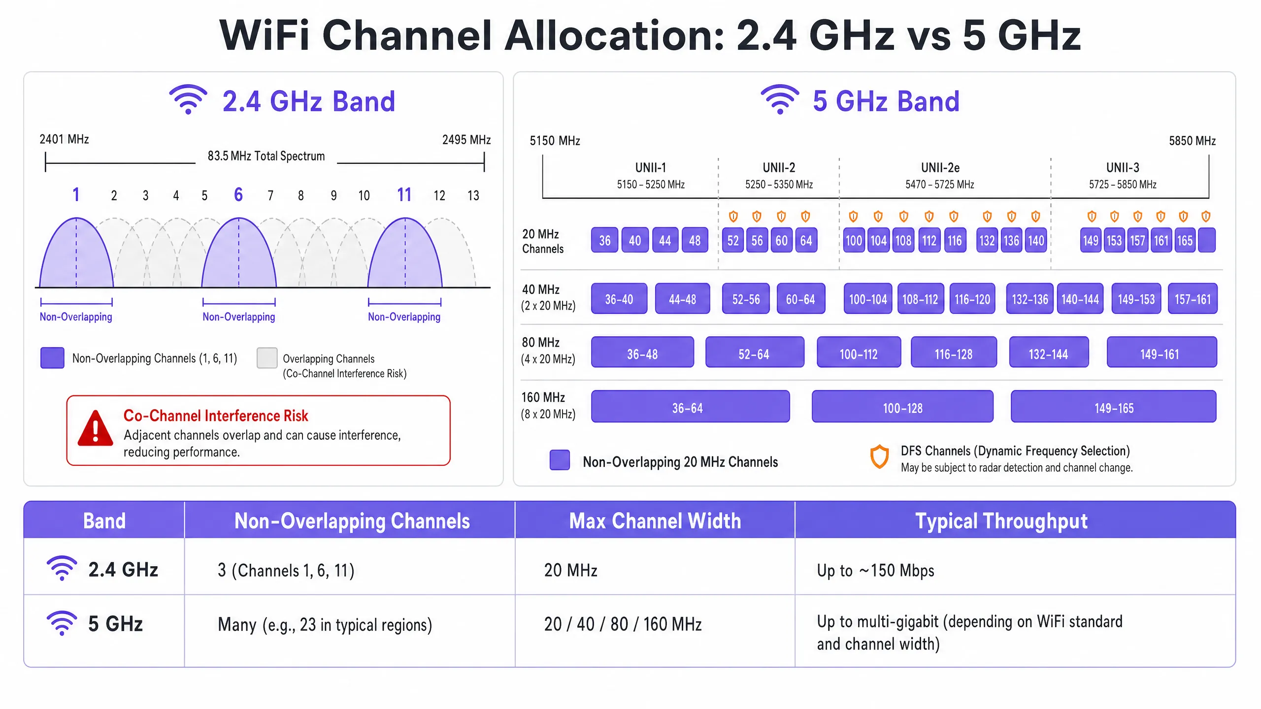
2.4 GHz频段提供更好的覆盖范围和墙壁穿透能力,但受到有限频谱的严重限制——总共约83.5 MHz。尽管根据监管域不同有11到14个信道,但真正不重叠的只有三个:信道1、6和11。在多AP部署中使用任何其他信道都会保证产生ACI。此外,该频段挤满了非WiFi干扰源,包括蓝牙设备、微波炉和在同一频谱中运行的DECT无绳电话。有关蓝牙低功耗如何与WiFi基础设施共存的详细分析,请参阅我们的指南 企业级BLE低功耗解析 。有关频段选择的更广泛处理,请参阅 Wi-Fi频率:2026年Wi-Fi频率指南 。
5 GHz的优势
5 GHz频段提供显著更多的频谱,在UNII-1、UNII-2、UNII-2e和UNII-3子频段中提供大量不重叠的20 MHz信道。该频段是企业客户端流量的正确默认选择。然而,它引入了两个关键复杂性:信道绑定权衡和动态频率选择(DFS)。
信道绑定——将20 MHz信道组合成40、80或160 MHz宽度——提高了单客户端的峰值吞吐量,但减少了可用的独立信道总数。在高密度环境中,这会导致严重的CCI。DFS信道(主要是UNII-2和UNII-2e)要求AP监控雷达信号,并在检测到时立即腾出信道,导致客户端断开连接。这对于靠近机场、气象站或军事设施的场所是一个关键考虑因素。
实施指南
更改WiFi信道绝不应基于猜测。它需要一种系统的、数据驱动的方法。
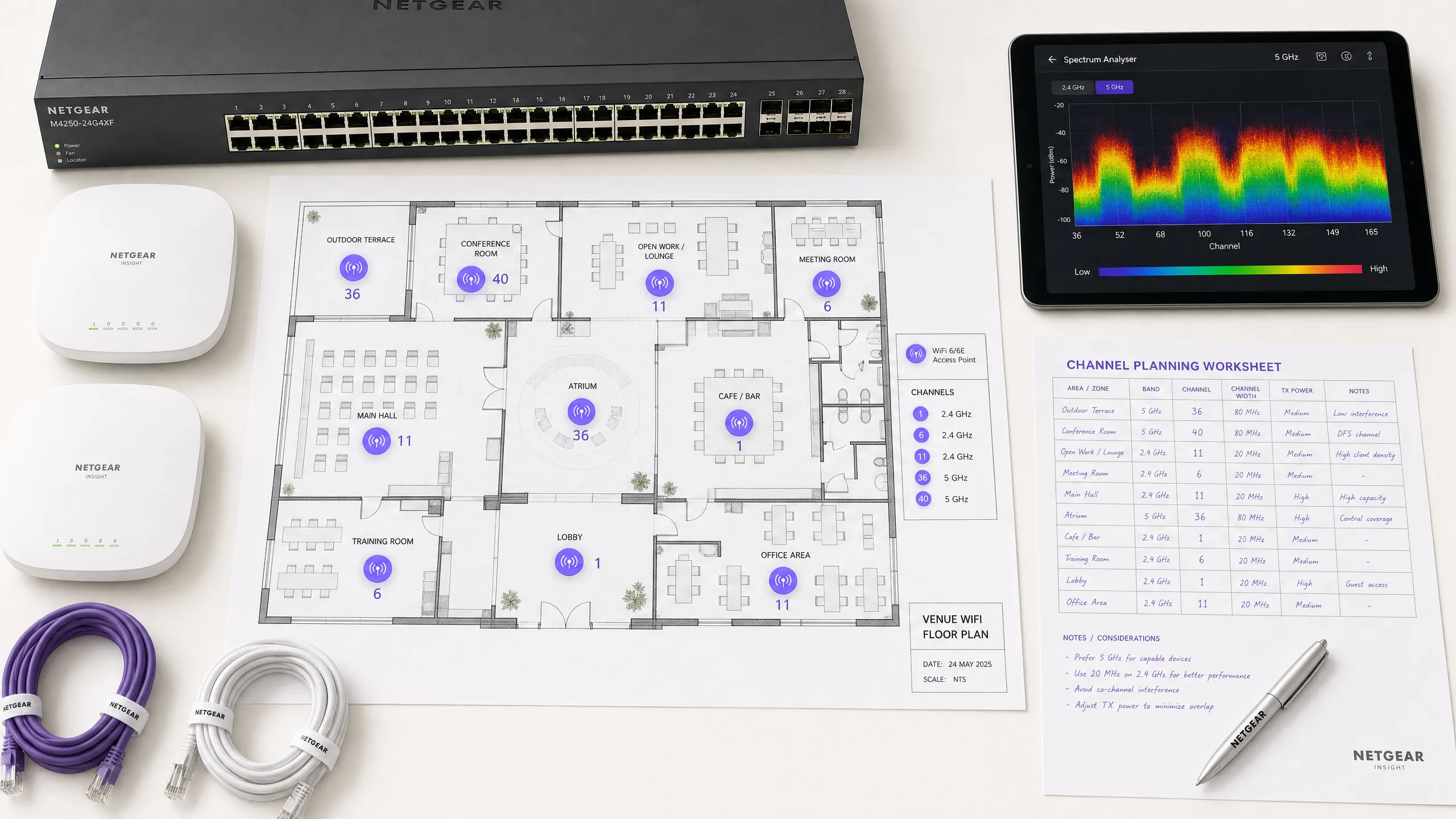
步骤1:进行频谱分析
在进行任何配置更改之前,建立经验性的基准。部署频谱分析仪——无论是专用硬件还是企业WLAN控制器内置工具——在两大频段上勘察RF环境。记录以下内容:非法或邻近AP及其信道分配、每个信道的本底噪声、非WiFi干扰源的存在以及当前AP发射功率水平。此基准是测量后续更改影响的参考点。
步骤2:制定信道计划
**对于2.4 GHz频段:**严格将信道池限制为信道1、6和11。将所有信道宽度设置为20 MHz——这是不可协商的。如果AP密度高到即使在1-6-11方案下也会导致显著的CCI,考虑以棋盘模式交替禁用2.4 GHz无线电,有效地将2.4 GHz AP密度减半,同时通过其余AP保持覆盖。
**对于5 GHz频段:**最大化使用可用的不重叠信道。在高密度部署中——会议中心、体育场、 交通 枢纽——强制执行20 MHz信道宽度,以最大化独立信道数量。仅在CCI不令人担忧的低密度区域增加到40 MHz。根据您的具体位置和与雷达源的接近程度,仔细评估DFS信道的包含。请查阅您国家监管机构的特定区域信道可用性列表。
步骤3:配置接入点
访问您的无线LAN控制器(WLC)或云管理仪表板以应用信道计划。大多数企业平台提供无线电资源管理(RRM)或Auto-RF功能,可动态分配信道和功率水平。
| 方法 | 最适合 | 风险 |
|---|---|---|
| 手动静态计划 | 复杂、高密度或靠近雷达的场所 | 需要随着环境变化进行定期重新勘测 |
| 自动RF / RRM | 更简单、低密度部署 | 在波动的RF环境中可能导致信道抖动 |
| 混合模式 | 大多数企业部署 | 需要谨慎的约束配置 |
在高度复杂的环境中,基于预测性勘测的手动静态信道计划通常比仅依赖Auto-RF产生更好的稳定性。必须并行调整发射功率——在密集部署中将5 GHz的AP发射功率降低到10–14 dBm,以缩小小区大小并减少AP间干扰。
步骤4:验证与监控
应用更改后,进行实施后的现场勘测以验证新的信道计划。通过您的 WiFi分析 平台监控关键绩效指标(KPI),重点关注重试率、每个AP的发送时间利用率、客户端关联计数和漫游行为。一个调优良好的RF环境应在高峰期间显示重试率低于10%和发送时间利用率低于70%。
最佳实践
**在高密度环境中强制执行20 MHz宽度。**在会议中心或体育场等环境中,优先考虑容量——更多的不重叠信道——而不是来自更宽信道的峰值单客户端吞吐量。总体网络性能将显著提高。
**积极实施频段引导。**配置频段引导,将支持5 GHz的客户端从拥挤的2.4 GHz频段推向5 GHz。大多数现代企业控制器原生支持此功能。将2.4 GHz保留给无法在5 GHz上运行的物联网设备和旧硬件。
**禁用旧数据速率。**在所有SSID上禁用802.11b数据速率(1、2、5.5、11 Mbps)。这些旧速率消耗不成比例的发送时间并减慢整个网络。将最低数据速率设置为12或24 Mbps,迫使客户端更早漫游并减少管理帧开销。
**安排定期的RF审计。**RF环境是动态的。新的邻近网络、建筑改造和新设备都会改变干扰格局。每季度安排RF审计,以保持您的信道计划最新。
**集成安全和网络管理。**确保启用非法AP检测和缓解,以防止未经授权的设备造成干扰或安全漏洞。有关更广泛的网络安全背景,包括访客网络上的内容过滤,请查阅 什么是DNS过滤?如何在宾客WiFi上阻止有害内容 。有关办公室特定的优化策略,请参阅 办公室Wi-Fi:优化您的现代办公室Wi-Fi网络 。
故障排除与风险缓解
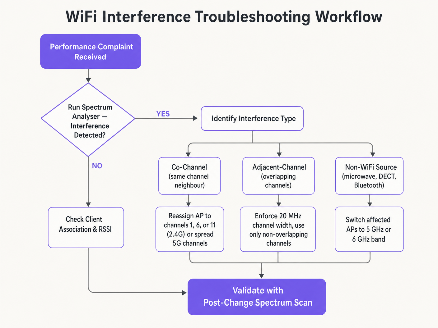
**症状:信号强,吞吐量差。**这是同信道干扰的标志。本底噪声低但发送时间饱和。审计信道分配和AP发射功率。降低发射功率并强制执行20 MHz信道宽度,以释放发送时间并改善空间复用。
**症状:特定区域随机客户端断开连接。**立即检查DFS事件日志。如果该区域的AP位于UNII-2或UNII-2e信道上且靠近雷达源,则法律要求它们腾出信道,导致客户端断开连接。从受影响区域的信道计划中排除这些特定的DFS信道。
**症状:信道计划不断自动更改。**这是由于过于敏感的Auto-RF算法对瞬态干扰做出反应而导致的信道抖动。限制RRM灵敏度设置,增加保持计时器,或迁移到基于勘测数据的静态信道计划。
**症状:特定区域信号良好但性能差。**来自微波炉、DECT电话或工业设备的非WiFi干扰可能正在抬高本底噪声。频谱分析仪将识别这些来源。补救措施是移除干扰源或将受影响的AP迁移到5 GHz或6 GHz频段,这些频段对大多数非WiFi 2.4 GHz干扰源免疫。
投资回报率与业务影响
优化WiFi信道是一项零成本的基础设施升级,可带来即时的、可衡量的回报。实施适当RF信道规划的组织通常报告在第一个季度内与WiFi相关的帮助台工单减少了30-40%。在 医疗保健 环境中,调优良好的RF环境可确保关键遥测数据的不间断流动,并支持符合临床设备通信要求。在 零售业 中,它保证了移动销售点系统的无缝运行、准确的位置分析和可靠的库存管理应用程序。
从资本支出的角度来看,正确的信道规划通常消除了对额外AP硬件的感知需求。许多认为自己存在AP密度问题的组织实际上存在信道规划问题。在进行任何严格的网络评估时,首先解决RF配置问题——在采购额外硬件之前——是标准做法。调优良好的RF环境还可以延长现有基础设施的运行生命周期,推迟昂贵的硬件更新周期,并为现有资本投资带来直接的、可量化的回报。
Definizioni chiave
Co-Channel Interference (CCI)
Interferenza che si verifica quando più access point o dispositivi client trasmettono contemporaneamente sullo stesso identico canale di frequenza.
Gestita da CSMA/CA, ma causa congestione e riduzione del throughput se eccessiva. Il sintomo principale è un'elevata occupazione del tempo di trasmissione (airtime utilisation) con un throughput ridotto.
Adjacent-Channel Interference (ACI)
Interferenza causata da dispositivi che trasmettono su canali di frequenza sovrapposti ma non identici, creando un rumore RF che CSMA/CA non è in grado di decodificare o gestire.
Più distruttiva della CCI. Innalza il rumore di fondo (noise floor), causa la perdita di pacchetti e costringe a ritrasmissioni. Causata dall'uso di canali diversi da 1, 6 e 11 sulla banda a 2.4 GHz.
Dynamic Frequency Selection (DFS)
Un meccanismo IEEE 802.11h che richiede agli access point WiFi di monitorare i segnali radar su determinati canali a 5 GHz e di abbandonare immediatamente il canale se viene rilevato un radar.
Interessa i canali UNII-2 e UNII-2e. Considerazione critica per le sedi vicine ad aeroporti, stazioni meteorologiche o siti militari, dove il rilevamento frequente di radar causa disconnessioni dei client.
Radio Resource Management (RRM)
Algoritmi automatizzati all'interno dei controller WLAN aziendali che regolano dinamicamente l'assegnazione dei canali e i livelli di potenza di trasmissione in base alle condizioni RF in tempo reale.
Utile per adattarsi a ambienti RF in continua evoluzione, ma può causare il 'channel churn' — frequenti cambi di canale — in ambienti instabili, interrompendo la connettività dei client.
Channel Bonding
Il processo di combinazione di più canali adiacenti a 20 MHz in canali più ampi a 40, 80 o 160 MHz per aumentare il throughput massimo del singolo client.
Riduce il numero totale di canali non sovrapposti disponibili, aumentando il rischio di CCI nelle distribuzioni dense. Dovrebbe essere evitato in ambienti aziendali ad alta densità.
Band Steering
Una funzionalità del controller WLAN che incoraggia i dispositivi client con funzionalità dual-band ad associarsi alla banda a 5 GHz anziché alla congestionata banda a 2.4 GHz.
Essenziale per il bilanciamento del carico nelle distribuzioni aziendali. Preserva lo spettro limitato a 2.4 GHz per i dispositivi IoT e l'hardware legacy che non possono funzionare a 5 GHz.
CSMA/CA
Carrier Sense Multiple Access with Collision Avoidance. Il protocollo di controllo dell'accesso al mezzo utilizzato dal WiFi IEEE 802.11, che richiede ai dispositivi di verificare che il canale sia libero prima di trasmettere.
Il meccanismo che regola il modo in che i dispositivi WiFi condividono il mezzo RF. Un'elevata CCI costringe i dispositivi ad attendere più a lungo per avere tempo di trasmissione libero, riducendo direttamente il throughput e aumentando la latenza.
Noise Floor
Il livello complessivo di energia RF di fondo presente in una determinata banda di frequenza, misurato in dBm. Un noise floor più elevato riduce il rapporto segnale-rumore (SNR) effettivo per le trasmissioni WiFi.
Innalzato da ACI, interferenze non WiFi e una scarsa pianificazione dei canali. Un noise floor elevato costringe i dispositivi a utilizzare schemi di modulazione e velocità di trasmissione dei dati inferiori, riducendo il throughput.
Spatial Reuse
La capacità di più access point di trasmettere contemporaneamente sullo stesso canale senza interferire tra loro, resa possibile dalla separazione fisica e da adeguati livelli di potenza di trasmissione.
Il meccanismo fondamentale che consente alle reti WiFi ad alta densità di scalare. Ottimizzato riducendo la potenza di trasmissione degli AP e utilizzando la larghezza di banda minima necessaria per i canali.
Esempi pratici
Un hotel da 200 camere riscontra frequenti lamentele per la lentezza del WiFi durante il picco serale. L'attuale implementazione utilizza canali a 40 MHz sulla banda a 2.4 GHz su 80 AP, con Auto-RF abilitato. I log del controller WLAN mostrano frequenti cambi di canale durante tutta la sera.
Fase 1 — Soluzione immediata: riconfigurare immediatamente tutte le radio a 2.4 GHz su larghezze di canale a 20 MHz. Limitare il pool di canali a 2.4 GHz esclusivamente ai canali 1, 6 e 11 all'interno del controller. Questa sola operazione eliminerà l'ACI nell'intera infrastruttura.
Fase 2 — Stabilizzare Auto-RF: esaminare i log degli eventi di Auto-RF. Se gli AP cambiano canale più di una volta all'ora, l'algoritmo sta reagendo a interferenze transitorie. Aumentare il timer di hold-down dell'RRM e ridurre la soglia di sensibilità. Se l'instabilità persiste, migrare a un piano di canali statico.
Fase 3 — Band steering: abilitare un band steering aggressivo per spingere i dispositivi dual-band sulla banda a 5 GHz. Questo riduce significativamente il carico sulla banda a 2.4 GHz durante i periodi di picco.
Fase 4 — Validazione: implementare un analizzatore di spettro dopo la modifica e monitorare i tassi di tentativi (retry rates) e l'utilizzo dell'airtime tramite la dashboard di WiFi analytics per 48 ore per confermare il miglioramento.
Una grande catena di vendita al dettaglio ha installato AP ogni 12 metri in un centro di distribuzione di 4.000 metri quadrati. Anche sulla banda a 5 GHz utilizzando canali a 20 MHz, l'interferenza co-canale (CCI) è elevata, il throughput è scarso e i dispositivi di scansione mobile subiscono frequenti disconnessioni durante le ore di picco dei turni.
Passo 1 — Verificare la potenza di trasmissione: gli AP sono quasi certamente configurati alla massima potenza TX (tipicamente 20–23 dBm). Con una spaziatura di 12 metri, questo crea una massiccia sovrapposizione delle celle. Ridurre la potenza TX a 10–12 dBm sulla banda a 5 GHz per rimpicciolire le dimensioni delle celle e ridurre l'interferenza tra AP.
Passo 2 — Disabilitare i data rate legacy: disabilitare tutti i data rate 802.11b/g inferiori a 12 Mbps. Questo costringe i dispositivi di scansione a eseguire il roaming verso l'AP più vicino anziché rimanere associati a un AP lontano con un data rate basso, il che consuma una quantità sproporzionata di airtime.
Passo 3 — Verificare il piano dei canali: assicurarsi che il piano dei canali a 5 GHz utilizzi il numero massimo di canali non sovrapposti disponibili. Con un'elevata densità di AP, ogni singolo canale è fondamentale.
Passo 4 — Validare con un'analisi post-modifica: condurre un'indagine sul campo con un analizzatore di spettro per confermare la riduzione della sovrapposizione tra AP e il miglioramento del rapporto segnale-rumore (SNR) in tutta l'area.
Domande di esercitazione
Q1. Stai implementando una nuova rete wireless in un edificio per uffici multi-tenant. La scansione dello spettro mostra un utilizzo intenso sui canali 1, 6 e 11 da parte dei tenant vicini. Un ingegnere junior suggerisce di utilizzare i canali 3, 8 e 13 per "evitare la congestione". Come rispondi e qual è la configurazione corretta?
Suggerimento: Considera la differenza tra Co-Channel Interference (CCI) e Adjacent-Channel Interference (ACI), e quale sia la più dannosa per le prestazioni della rete.
Visualizza risposta modello
Il suggerimento dell'ingegnere junior è errato e causerebbe un grave degrado delle prestazioni. I canali 3, 8 e 13 si sovrappongono rispettivamente ai canali 1, 6 e 11, il che introdurrebbe un'interferenza da canale adiacente (Adjacent-Channel Interference) — la forma più distruttiva di interferenza WiFi. L'ACI si manifesta come puro rumore RF che il CSMA/CA non può gestire, causando perdita di pacchetti e ritrasmissioni. La configurazione corretta consiste nell'implementare sui canali 1, 6 e 11. Sebbene ciò causerà interferenze co-canale (Co-Channel Interference) con i tenant vicini, il CSMA/CA è in grado di gestire la CCI in modo efficiente facendo fare a turno ai dispositivi. Le prestazioni complessive saranno significativamente migliori rispetto all'uso dell'ACI.
Q2. L'implementazione in uno stadio utilizza canali a 80 MHz sulla banda a 5 GHz per pubblicizzare velocità "Gigabit WiFi" durante gli eventi. Gli utenti segnalano tempi di caricamento lenti, disconnessioni frequenti e scarsa qualità dello streaming video durante i picchi di affluenza. L'hardware degli AP è una moderna apparecchiatura WiFi 6. Qual è il difetto architetturale e quale la soluzione?
Suggerimento: Valuta il compromesso tra il throughput massimo del singolo client e la capacità complessiva della rete in un ambiente ad alta densità.
Visualizza risposta modello
Il difetto architetturale è l'uso di canali con ampiezza di 80 MHz in un ambiente ad alta densità. Ciascun canale a 80 MHz unisce quattro canali a 20 MHz, riducendo drasticamente il numero totale di canali non sovrapposti disponibili nell'intera installazione. Con molti AP costretti a riutilizzare gli stessi canali ampi, la Co-Channel Interference diventa grave. La soluzione consiste nel ridurre l'ampiezza dei canali a 20 MHz su tutti gli AP. Ciò aumenta il numero di canali indipendenti disponibili, riduce la CCI e migliora significativamente la capacità complessiva della rete. Il throughput di picco per singolo client diminuirà, ma il numero di client che possono essere serviti contemporaneamente — e la qualità della loro esperienza — aumenterà in modo sostanziale.
Q3. La rete di un ospedale presenta disconnessioni intermittenti dei client che interessano i dispositivi medici nei reparti vicini all'eliporto sul tetto della struttura. Gli AP interessati sono configurati per utilizzare i canali 52, 56, 60 e 64. Qual è la causa più probabile e quale la corretta risoluzione?
Suggerimento: Considera i requisiti normativi per gli specifici canali a 5 GHz in uso e quali sistemi operano vicino a una pista di atterraggio per elicotteri.
Visualizza risposta modello
I canali 52, 56, 60 e 64 sono canali UNII-2 DFS. Gli elicotteri che utilizzano l'eliporto, o i sistemi radar aeronautici associati, stanno probabilmente attivando eventi di rilevamento radar DFS sugli AP in quella zona. Quando viene rilevato un radar, gli AP sono legalmente tenuti a liberare immediatamente tali canali, causando la disconnessione dei client. La corretta risoluzione consiste nell'escludere tutti i canali DFS dal piano dei canali per gli AP nelle zone vicine all'eliporto. Riconfigura tali AP per utilizzare i canali UNII-1 (36, 40, 44, 48) o i canali UNII-3 (149, 153, 157, 161, 165), che non sono soggetti ai requisiti DFS.
Continua a leggere questa serie
Comprendere l'RSSI e la potenza del segnale per una pianificazione ottimale dei canali
Questa guida offre un approfondimento tecnico completo su RSSI, Signal-to-Noise Ratio (SNR) e principi di propagazione RF per una pianificazione ottimale dei canali. Fornisce a IT manager, architetti di rete e direttori operativi delle strutture strategie pratiche per mitigare l'interferenza co-canale e adiacente, ottimizzare il posizionamento degli AP e sfruttare gli analytics per un impatto aziendale misurabile nei settori dell'ospitalità, del retail e pubblico.
20MHz vs 40MHz vs 80MHz: quale ampiezza di canale dovresti utilizzare?
Questa guida fornisce un riferimento tecnico definitivo e neutrale rispetto ai vendor per IT manager, architetti di rete e direttori operativi di location sulla selezione della corretta ampiezza di canale WiFi — 20MHz, 40MHz o 80MHz — nelle implementazioni aziendali nei settori dell'ospitalità, del retail, degli eventi e del settore pubblico. Copre i meccanismi IEEE 802.11 alla base, i compromessi di capacità nel mondo reale e una guida all'implementazione passo-passo per aiutare i team a prendere la decisione giusta in questo trimestre. Comprendere la selezione dell'ampiezza di canale è una delle decisioni a più alto impatto in qualsiasi progettazione di LAN wireless, influenzando direttamente il throughput, le interferenze, il supporto alla densità dei client e l'affidabilità dei servizi rivolti agli ospiti.
Wi-Fi 6 vs Wi-Fi 5: Risolve l'Interferenza di Canale?
Questa guida offre un approfondimento tecnico su come il Wi-Fi 6 (802.11ax) affronti l'interferenza di canale in ambienti aziendali ad alta densità attraverso OFDMA e BSS Coloring. Fornisce a IT manager, architetti di rete e CTO strategie di implementazione pratiche, casi di studio reali nei settori dell'ospitalità e della sanità, e un framework per valutare il ROI degli aggiornamenti infrastrutturali nei luoghi in cui le prestazioni wireless sono fondamentali per il business.