Comprendere il BSSID e gli algoritmi di selezione del canale
Questa guida di riferimento tecnico autorevole fa chiarezza sull'architettura BSSID e sugli algoritmi di selezione dinamica dei canali per le installazioni wireless aziendali. Fornisce strategie di implementazione pratiche per architetti IT e team di gestione delle sedi per eliminare i client "sticky", mitigare le interferenze co-canale e costruire una solida base RF. Un BSSID stabile e un piano di canali adeguato rappresentano inoltre un prerequisito fondamentale per ottenere analisi di localizzazione accurate e business intelligence attraverso piattaforme come Purple.
Ascolta questa guida
Visualizza trascrizione del podcast
এক্সিকিউটিভ সামারি
জটিল পরিবেশ পরিচালনা করা এন্টারপ্রাইজ আইটি লিডারদের জন্য — হাই-ডেনসিটি স্টেডিয়াম থেকে শুরু করে বিশাল হাসপাতাল ক্যাম্পাস পর্যন্ত — র-ওয়্যারলেস কভারেজ এখন আর প্রধান চ্যালেঞ্জ নয়। আধুনিক ওয়্যারলেস ডিপ্লয়মেন্টের ক্ষেত্রে রোমিং বাউন্ডারিতেই মূলত ব্যর্থতা দেখা যায়, যার প্রধান কারণ হলো দুর্বল BSSID ট্রানজিশন ম্যানেজমেন্ট এবং সাব-অপ্টিমাল চ্যানেল অ্যালোকেশন।
এই টেকনিক্যাল রেফারেন্স গাইডটি বেসিক সার্ভিস সেট আইডেন্টিফায়ার (BSSID) এবং ডায়নামিক চ্যানেল সিলেকশন অ্যালগরিদমের মেকানিক্সের উপর একটি ভেন্ডর-নিউট্রাল, ডিপ-ডাইভ অ্যানালাইসিস প্রদান করে। ক্লায়েন্ট ডিভাইসগুলো কীভাবে BSSID-কে ইন্টারপ্রেট করে এবং এন্টারপ্রাইজ কন্ট্রোলারগুলো কীভাবে RF স্পেকট্রাম পরিচালনা করে তা বোঝার মাধ্যমে, আইটি আর্কিটেক্টরা "স্টিকি ক্লায়েন্ট" দূর করতে, কো-চ্যানেল ইন্টারফারেন্স কমাতে এবং যেকোনো ভেন্যু স্কেলে নির্বিঘ্ন রোমিং নিশ্চিত করতে পারেন। উপরন্তু, একটি স্থিতিশীল RF ফাউন্ডেশন হলো WiFi Analytics -এর মাধ্যমে সঠিক লোকেশন ডেটা বের করার একটি প্রত্যক্ষ পূর্বশর্ত, যা সরাসরি বিজনেস ইন্টেলিজেন্স এবং ROI-কে প্রভাবিত করে। আপনি কোনো হোটেল চেইন, রিটেইল এস্টেট বা পাবলিক-সেক্টর ফ্যাসিলিটি পরিচালনা করুন না কেন, এই গাইডের নীতিগুলো সর্বজনীনভাবে প্রযোজ্য।
টেকনিক্যাল ডিপ-ডাইভ
BSSID বনাম SSID-এর পার্থক্য
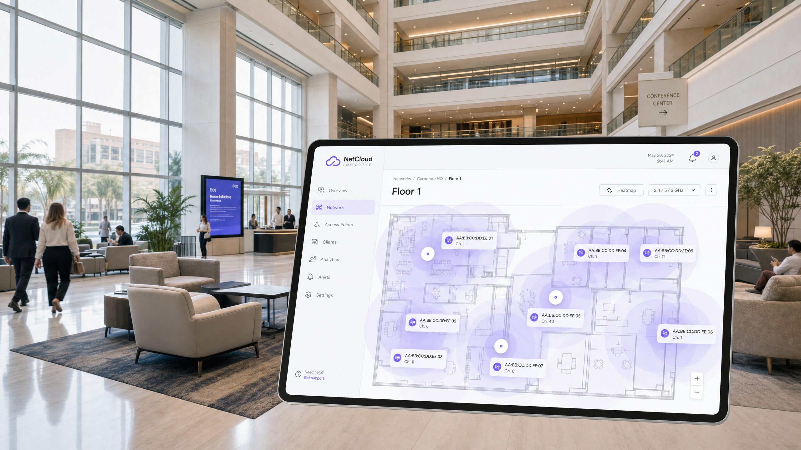
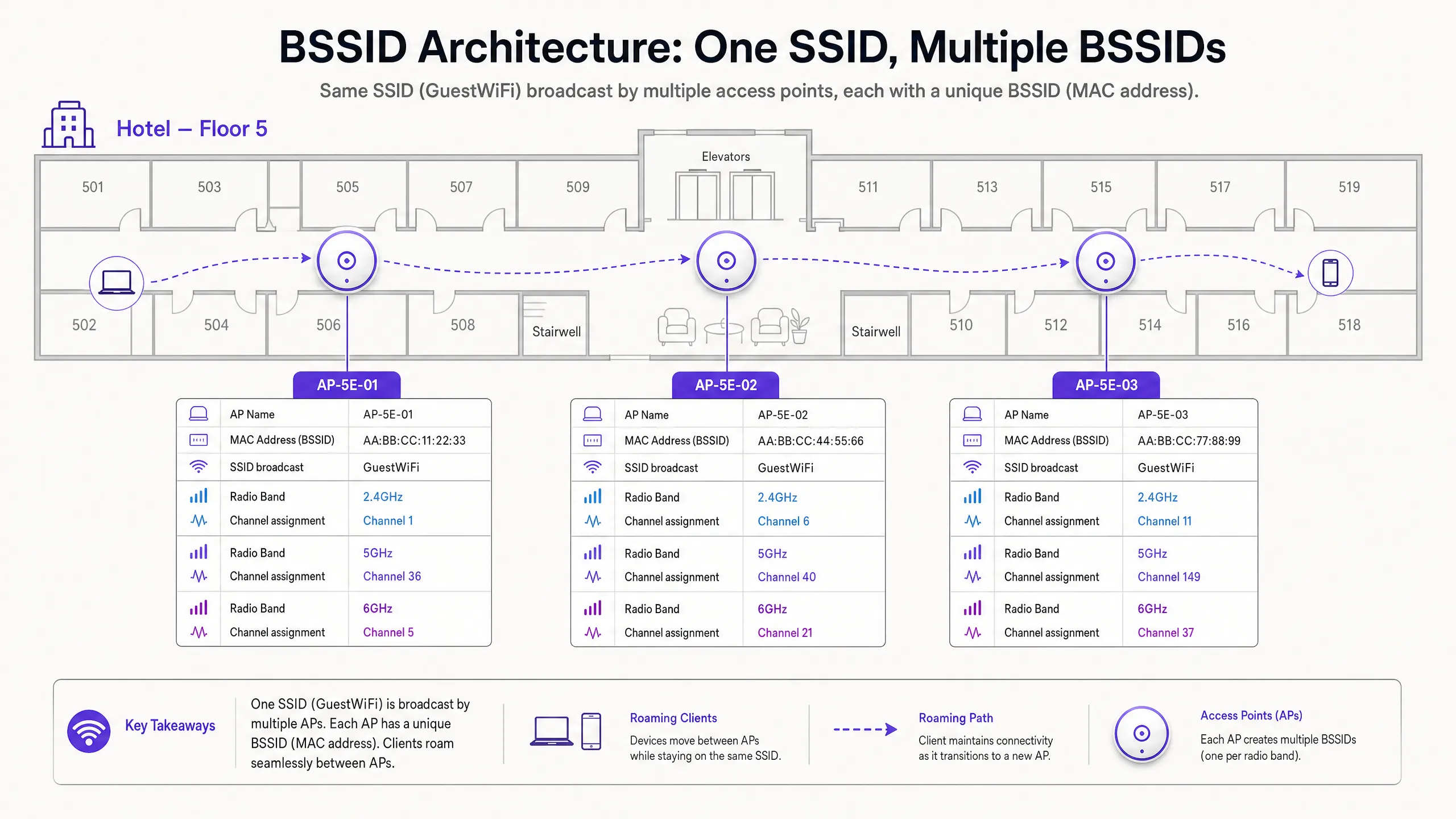
যখন কোনো ব্যবহারকারী আপনার Guest WiFi নেটওয়ার্কে কানেক্ট করেন, তখন তারা SSID — সার্ভিস সেট আইডেন্টিফায়ার দেখতে পান। এটি হলো নেটওয়ার্ক দ্বারা ব্রডকাস্ট করা মানুষের পড়ার যোগ্য লেবেল, যেমন "Hotel_Guest" বা "RetailWiFi"। SSID হলো সম্পূর্ণভাবে একটি লজিক্যাল আইডেন্টিফায়ার। প্রকৃত 802.11 অ্যাসোসিয়েশন ফিজিক্যাল লেয়ারে BSSID-এর সাথে ঘটে。
BSSID (বেসিক সার্ভিস সেট আইডেন্টিফায়ার) হলো সেই SSID ব্রডকাস্ট করা অ্যাক্সেস পয়েন্টের নির্দিষ্ট রেডিও ইন্টারফেসের MAC অ্যাড্রেস। একটি মাল্টি-AP পরিবেশে, একটি একক SSID ডজন বা শত শত ইউনিক BSSID দ্বারা ব্রডকাস্ট করা হয়। একটি ডুয়াল-রেডিও অ্যাক্সেস পয়েন্ট যা একটি SSID ব্রডকাস্ট করে তা দুটি আলাদা BSSID উপস্থাপন করবে — প্রতি রেডিও ব্যান্ডের জন্য একটি। একটি ট্রাই-রেডিও Wi-Fi 6E অ্যাক্সেস পয়েন্ট তিনটি উপস্থাপন করবে।
এই পার্থক্যের উল্লেখযোগ্য অপারেশনাল প্রভাব রয়েছে। যখন আপনি কোনো রোমিং অভিযোগের ট্রাবলশুটিং করছেন, তখন আপনি SSID নিয়ে তদন্ত করছেন না — আপনি BSSID ট্রানজিশন নিয়ে তদন্ত করছেন। লিনাক্সে wpa_cli বা ম্যাকওএস ওয়্যারলেস ডায়াগনস্টিকস ইউটিলিটির মতো ক্লায়েন্ট-সাইড ডায়াগনস্টিক টুলগুলো নির্দিষ্ট BSSID (MAC অ্যাড্রেস) প্রকাশ করবে যার সাথে একটি ডিভাইস যুক্ত আছে, সাথে চ্যানেল এবং RSSI-ও দেখাবে।
রোমিং মেকানিজম: আসলে কার নিয়ন্ত্রণে?
এটি এন্টারপ্রাইজ ওয়্যারলেস আর্কিটেকচারের সবচেয়ে ভুল বোঝা দিক। 802.11 স্ট্যান্ডার্ড রোমিংয়ের সিদ্ধান্তটি সম্পূর্ণভাবে ক্লায়েন্ট ডিভাইসের উপর ছেড়ে দেয়। নেটওয়ার্ক ইনফ্রাস্ট্রাকচার কোনো ক্লায়েন্টকে রোম করতে বাধ্য করতে পারে না। এটি কেবল সেই শর্তগুলোকে প্রভাবিত করতে পারে যা রোমিংয়ের সম্ভাবনা কম বা বেশি করে।
একটি ক্লায়েন্ট ডিভাইস তার বর্তমান BSSID-এর রিসিভড সিগন্যাল স্ট্রেংথ ইন্ডিকেটর (RSSI) এবং সিগন্যাল-টু-নয়েজ রেশিও (SNR) পার্শ্ববর্তী BSSID-গুলোর সাথে মূল্যায়ন করে। যখন বর্তমান BSSID একটি ডিভাইস-নির্দিষ্ট থ্রেশহোল্ডের নিচে নেমে যায় — সাধারণত অ্যাপল iOS ডিভাইসের জন্য প্রায় -70 dBm এবং অনেক Android ডিভাইসের জন্য -75 dBm — তখন ক্লায়েন্ট প্রোব রিকোয়েস্ট ব্রডকাস্ট করে একটি ভালো BSSID-এর জন্য স্ক্যান শুরু করে। কাছাকাছি থাকা অ্যাক্সেস পয়েন্টগুলো প্রোব রেসপন্স দিয়ে সাড়া দেয়। ক্লায়েন্ট এই রেসপন্সগুলো মূল্যায়ন করে এবং নির্বাচিত BSSID-তে একটি 802.11 অথেনটিকেশন এবং রি-অ্যাসোসিয়েশন শুরু করে।
যদি চ্যানেল প্ল্যানিং দুর্বল হয়, তবে ক্লায়েন্ট অ্যাডজাসেন্ট চ্যানেল ইন্টারফারেন্সের সম্মুখীন হতে পারে, যা পার্শ্ববর্তী BSSID-গুলোর বীকন ফ্রেমগুলোকে করাপ্ট করে। এটি "স্টিকি ক্লায়েন্ট" ফেনোমেনন-এর দিকে নিয়ে যায় — একটি ডিভাইস একটি দুর্বল, দূরবর্তী BSSID ধরে রাখে কারণ এটি পরিষ্কারভাবে শক্তিশালী, কাছাকাছি বিকল্পটি শুনতে পায় না। এর ফলাফল হলো থ্রুপুট কমে যাওয়া, ভিওআইপি (VoIP) কল ড্রপ হওয়া এবং অ্যাপ্লিকেশন সেশন ব্যর্থ হওয়া।
চ্যানেল সিলেকশন: RF আর্কিটেকচার ফাউন্ডেশন
2.4 GHz সীমাবদ্ধতা
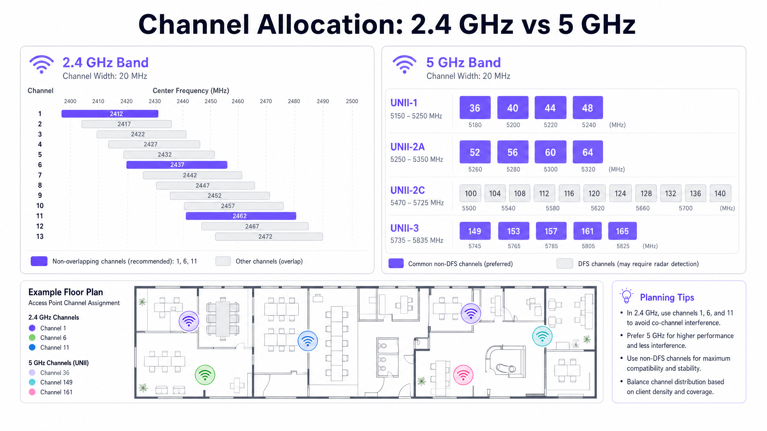
2.4 GHz ব্যান্ডটি 2.400 GHz থেকে 2.4835 GHz পর্যন্ত 83.5 MHz স্পেকট্রাম জুড়ে বিস্তৃত। প্রতিটি 802.11 চ্যানেল 20 MHz চওড়া। চ্যানেল সেন্টার ফ্রিকোয়েন্সিগুলোর মধ্যে 5 MHz স্পেসিং থাকার কারণে, সংলগ্ন চ্যানেলগুলোর মধ্যে উল্লেখযোগ্য ওভারল্যাপ তৈরি হয়। 2.4 GHz ব্যান্ডে শুধুমাত্র 1, 6 এবং 11 নম্বর চ্যানেলগুলো নন-ওভারল্যাপিং।
2.4 GHz ব্যান্ডে 1, 6 বা 11 ছাড়া অন্য কোনো চ্যানেল ব্যবহার করলে অ্যাডজাসেন্ট চ্যানেল ইন্টারফারেন্স (ACI) তৈরি হয়। ACI স্পষ্টভাবে কো-চ্যানেল ইন্টারফারেন্স (CCI)-এর চেয়ে খারাপ কারণ এটি ডেটা প্যাকেটগুলোকে সম্পূর্ণভাবে করাপ্ট করে, যার ফলে রিট্রান্সমিশনের প্রয়োজন হয়। অন্যদিকে, CCI ডিভাইসগুলোকে CSMA/CA-এর মাধ্যমে কো-অপারেটিভভাবে এয়ারটাইম শেয়ার করতে বাধ্য করে, যা থ্রুপুট কমায় কিন্তু প্যাকেট করাপ্ট করে না। নিয়মটি পরম: 2.4 GHz ডিপ্লয়মেন্টে অবশ্যই শুধুমাত্র 1, 6 এবং 11 নম্বর চ্যানেল ব্যবহার করতে হবে।
আধুনিক এন্টারপ্রাইজ পরিবেশে ফ্রিকোয়েন্সি ব্যান্ডগুলো কীভাবে ইন্টারঅ্যাক্ট করে সে সম্পর্কে আরও বিস্তৃত ধারণার জন্য, আমাদের Wi-Fi Frequencies: A Guide to Wi-Fi Frequencies in 2026 গাইডটি দেখুন।
5 GHz সুযোগ এবং DFS জটিলতা
5 GHz ব্যান্ড উল্লেখযোগ্যভাবে বেশি স্পেকট্রাম অফার করে। ইউকে এবং ইইউ রেগুলেটরি ডোমেইনে, UNII-1 (5.150–5.250 GHz), UNII-2A (5.250–5.350 GHz), UNII-2C (5.470–5.725 GHz), এবং UNII-3 (5.735–5.835 GHz) জুড়ে 19টি পর্যন্ত নন-ওভারল্যাপিং 20 MHz চ্যানেল উপলব্ধ রয়েছে।
যাইহোক, UNII-2A এবং UNII-2C চ্যানেলগুলো DFS (ডায়নামিক ফ্রিকোয়েন্সি সিলেকশন) রেঞ্জের মধ্যে পড়ে। এই চ্যানেলগুলো আবহাওয়া রাডার, মিলিটারি রাডার এবং এয়ার ট্রাফিক কন্ট্রোল সিস্টেমের সাথে শেয়ার করা হয়। যদি কোনো অ্যাক্সেস পয়েন্ট একটি DFS চ্যানেলে রাডার পালস শনাক্ত করে, তবে তাকে অবিলম্বে চ্যানেলটি খালি করতে হবে এবং 30 মিনিটের জন্য সেখানে সাইলেন্ট থাকতে হবে। এটি ইউরোপে ETSI EN 301 893 এবং মার্কিন যুক্তরাষ্ট্রে FCC Part 15-এর অধীনে একটি রেগুলেটরি ম্যান্ডেট।
বিমানবন্দর, মিলিটারি স্থাপনা বা আবহাওয়া স্টেশনগুলোর কাছাকাছি ভেন্যুগুলোর জন্য — যা Hospitality এবং Transport ডিপ্লয়মেন্টে সাধারণ — DFS ইভেন্টগুলো প্রতিদিন একাধিকবার ঘটতে পারে, যার ফলে অপ্রত্যাশিত AP চ্যানেল পরিবর্তন এবং ক্লায়েন্ট ডিসকানেকশন হতে পারে।
ডায়নামিক চ্যানেল অ্যাসাইনমেন্ট (DCA)
আধুনিক এন্টারপ্রাইজ ওয়্যারলেস ল্যান কন্ট্রোলারগুলো ডায়নামিক চ্যানেল অ্যাসাইনমেন্ট (DCA) অ্যালগরিদমের মাধ্যমে চ্যানেল ম্যানেজমেন্টের সমাধান করে। এই অ্যালগরিদমগুলো ক্রমাগত মূল্যায়ন করে:
| মেট্রিক | বিবরণ | প্রভাব |
|---|---|---|
| চ্যানেল ইউটিলাইজেশন | মাধ্যমটি ব্যস্ত থাকার সময়ের শতাংশ | উচ্চ ইউটিলাইজেশন চ্যানেল পরিবর্তনের বিবেচনাকে ট্রিগার করে |
| নয়েজ ফ্লোর | নন-802.11 RF ইন্টারফারেন্স (ব্লুটুথ, মাইক্রোওয়েভ ইত্যাদি) | বর্ধিত নয়েজ ফ্লোর কার্যকর SNR কমিয়ে দেয় |
| নেইবার AP RSSI | কো-চ্যানেল এবং অ্যাডজাসেন্ট-চ্যানেল AP-গুলোর সিগন্যাল স্ট্রেংথ | উচ্চ ওভারল্যাপ চ্যানেল রিব্যালেন্সিং ট্রিগার করে |
| DFS ইভেন্ট | বর্তমান চ্যানেলে রাডার শনাক্তকরণ | বাধ্যতামূলক তাৎক্ষণিক চ্যানেল পরিবর্তন |
যদিও একটি স্বাস্থ্যকর RF পরিবেশ বজায় রাখার জন্য DCA অপরিহার্য, অত্যধিক আক্রমণাত্মক অ্যালগরিদম সেটিংস নেটওয়ার্কের অস্থিরতা সৃষ্টি করে। প্রতিবার যখন কোনো AP চ্যানেল পরিবর্তন করে, তখন সমস্ত সংযুক্ত ক্লায়েন্ট সাময়িকভাবে ডিসকানেক্ট হয়ে যায় এবং তাদের পুনরায় অ্যাসোসিয়েট হতে হয়। একটি কীনোট চলাকালীন কনফারেন্স সেন্টারে, অথবা পিক ট্রেডিং আওয়ারে Retail শপ ফ্লোরে, এটি অপারেশনালভাবে অগ্রহণযোগ্য।
সুপারিশকৃত পদ্ধতি হলো DCA-কে একটি নির্ধারিত ভিত্তিতে চালানোর জন্য কনফিগার করা — সাধারণত ওভারনাইট মেইনটেন্যান্স উইন্ডোর সময় — আনশিডিউলড পরিবর্তনের জন্য 30% বা তার বেশি ইন্টারফারেন্স থ্রেশহোল্ড ট্রিগার সহ। বাধ্যতামূলক DFS রাডার ইভেশন ইভেন্টগুলোই কেবল এই শিডিউলিং শৃঙ্খলার একমাত্র ব্যতিক্রম।
ইমপ্লিমেন্টেশন গাইড
নিম্নলিখিত ভেন্ডর-নিউট্রাল ইমপ্লিমেন্টেশন ধাপগুলো Hospitality , Retail , Healthcare এবং পাবলিক-সেক্টর পরিবেশ জুড়ে এন্টারপ্রাইজ ডিপ্লয়মেন্টের ক্ষেত্রে প্রযোজ্য।
ধাপ ১ — লিগ্যাসি ডেটা রেট ডিজেবল করুন। সমস্ত অ্যাক্সেস পয়েন্ট রেডিও প্রোফাইল থেকে 802.11b ডেটা রেট (1, 2, 5.5 এবং 11 Mbps) সরিয়ে ফেলুন। এই লিগ্যাসি রেটগুলো অসামঞ্জস্যপূর্ণ এয়ারটাইম খরচ করে এবং স্টিকি ক্লায়েন্ট আচরণের প্রধান চালক। ডিজেবল করা হলে, ন্যূনতম কার্যকর কানেকশন রেট বৃদ্ধি পায়, যা ক্লায়েন্টদের সঠিক ফিজিক্যাল লোকেশনে তাদের রোমিং থ্রেশহোল্ডে পৌঁছাতে বাধ্য করে।
ধাপ ২ — AP ট্রান্সমিট পাওয়ার কমান। সর্বোচ্চ ট্রান্সমিট পাওয়ারে (20 dBm) AP চালানো ওভারসাইজড সেল তৈরি করে এবং সঠিক BSSID রোমিংয়ে বাধা দেয়। 2.4 GHz ট্রান্সমিট পাওয়ার 8–12 dBm এবং 5 GHz ট্রান্সমিট পাওয়ার 12–17 dBm-এ কমিয়ে আনুন, যা আপনার পরিবেশের সবচেয়ে দুর্বল ক্লায়েন্ট ডিভাইসের ট্রান্সমিট পাওয়ারের সাথে মিল রেখে ক্যালিব্রেট করা উচিত।
ধাপ ৩ — চ্যানেল উইডথ সীমাবদ্ধ করুন। হাই-ডেনসিটি পরিবেশে, 5 GHz চ্যানেলগুলোকে 20 MHz-এ সীমাবদ্ধ করুন। যদিও 40 MHz এবং 80 MHz চ্যানেল বন্ডিং তাত্ত্বিক সিঙ্গেল-ডিভাইস থ্রুপুট বাড়ায়, এটি উপলব্ধ নন-ওভারল্যাপিং চ্যানেলগুলোকে কমিয়ে দেয় এবং নয়েজ ফ্লোর বাড়ায়, যার ফলে ডেন্স ডিপ্লয়মেন্টে মারাত্মক CCI দেখা দেয়।
ধাপ ৪ — DCA মেইনটেন্যান্স উইন্ডো কনফিগার করুন। ওভারনাইট মেইনটেন্যান্স উইন্ডোর সময় এক্সিকিউট করার জন্য আপনার কন্ট্রোলারের DCA অ্যালগরিদম সেট করুন। আনশিডিউলড ট্রিগারের জন্য 30% ইন্টারফারেন্স থ্রেশহোল্ড কনফিগার করুন। এটি RF হাইজিন বজায় রাখার পাশাপাশি অপারেশনাল আওয়ারে ব্যাঘাতমূলক চ্যানেল পরিবর্তন রোধ করে।
ধাপ ৫ — DFS ফলব্যাক স্ট্র্যাটেজি প্ল্যান করুন। পরিচিত রাডার প্রক্সিমিটি থাকা ভেন্যুগুলোর জন্য, মিশন-ক্রিটিকাল AP-গুলোর জন্য DCA পুল থেকে DFS চ্যানেলগুলো বাদ দিন। প্রাইমারি চ্যানেল প্ল্যান হিসেবে UNII-1 (36, 40, 44, 48) এবং UNII-3 (149, 153, 157, 161, 165) নন-DFS চ্যানেলগুলোর উপর নির্ভর করুন। বৃহত্তর নেটওয়ার্ক অ্যাক্সেস কন্ট্রোল আধুনিকীকরণের নির্দেশনার জন্য, La lista de verificación para migrar de NAC heredado a NAC nativo de la nube দেখুন।
ধাপ ৬ — ব্যান্ড স্টিয়ারিং এনাবল করুন। ডুয়াল-ব্যান্ড সক্ষম ক্লায়েন্টদের 5 GHz ব্যান্ডে পুশ করার জন্য ব্যান্ড স্টিয়ারিং কনফিগার করুন, যা লিগ্যাসি ডিভাইস এবং IoT ইকুইপমেন্টের জন্য 2.4 GHz স্পেকট্রাম মুক্ত করে। এন্টারপ্রাইজ পরিবেশে IoT এবং BLE কো-এক্সিস্টেন্সের প্রসঙ্গের জন্য, BLE Low Energy Explained for Enterprise দেখুন।
বেস্ট প্র্যাকটিস
নিম্নলিখিত বেস্ট প্র্যাকটিসগুলো IEEE 802.11 স্ট্যান্ডার্ড, Wi-Fi অ্যালায়েন্স সার্টিফিকেশন রিকোয়ারমেন্ট এবং ভেন্ডর-নিউট্রাল এন্টারপ্রাইজ ডিপ্লয়মেন্ট গাইডলাইনের সাথে সামঞ্জস্যপূর্ণ।
মিনিমাম RSSI থ্রেশহোল্ড: -80 dBm-এর নিচে RSSI থাকা ক্লায়েন্টদের অ্যাসোসিয়েশন প্রত্যাখ্যান করার জন্য অ্যাক্সেস পয়েন্টগুলো কনফিগার করুন। এটি দুর্বল ক্লায়েন্টদের দূরবর্তী AP-এর সাথে যুক্ত হতে এবং কম ডেটা রেটে এয়ারটাইম খরচ করতে বাধা দেয়। বেশিরভাগ এন্টারপ্রাইজ কন্ট্রোলার এটিকে "মিনিমাম RSSI" বা "ক্লায়েন্ট এক্সক্লুশন" থ্রেশহোল্ড হিসেবে প্রকাশ করে।
802.11r ফাস্ট BSS ট্রানজিশন: ভয়েস বা রিয়েল-টাইম অ্যাপ্লিকেশন সাপোর্ট করে এমন সমস্ত SSID-তে 802.11r (ফাস্ট BSS ট্রানজিশন) এনাবল করুন। এটি রোমিং হ্যান্ডঅফ সময়কে 50–200 ms (স্ট্যান্ডার্ড রি-অ্যাসোসিয়েশন) থেকে 50 ms-এর নিচে কমিয়ে দেয়, যা BSSID ট্রানজিশনের সময় ভিওআইপি (VoIP) কল ড্রপ প্রতিরোধ করে।
802.11k এবং 802.11v নেইবার রিপোর্টিং: ক্লায়েন্টদের নেইবার AP লিস্ট এবং ট্রানজিশন রিকমেন্ডেশন প্রদান করতে 802.11k (রেডিও রিসোর্স ম্যানেজমেন্ট) এবং 802.11v (BSS ট্রানজিশন ম্যানেজমেন্ট) এনাবল করুন। যদিও ক্লায়েন্ট এখনও চূড়ান্ত রোমিং সিদ্ধান্ত নেয়, এই প্রোটোকলগুলো তাকে দ্রুত, আরও তথ্যভিত্তিক পছন্দ করার জন্য প্রয়োজনীয় তথ্য প্রদান করে।
WPA3 এবং OWE: গেস্ট নেটওয়ার্কগুলোর জন্য, পাসওয়ার্ডের প্রয়োজন ছাড়াই পার-সেশন এনক্রিপশন প্রদান করতে WPA3-SAE বা অপরচুনিস্টিক ওয়্যারলেস এনক্রিপশন (OWE) ডিপ্লয় করুন। এটি ট্রানজিটে থাকা গেস্ট ডেটার জন্য GDPR ডেটা সুরক্ষা বাধ্যবাধকতার সাথে সামঞ্জস্যপূর্ণ এবং কার্ডহোল্ডার ডেটা স্পর্শ করে এমন যেকোনো নেটওয়ার্ক সেগমেন্টের জন্য এটি একটি PCI DSS রিকোয়ারমেন্ট।
নিয়মিত RF অডিট: প্রতি 12 মাসে বা ভেন্যুতে কোনো উল্লেখযোগ্য ফিজিক্যাল পরিবর্তনের (নতুন পার্টিশন, ইকুইপমেন্ট ইনস্টলেশন, আসবাবপত্রের পুনর্বিন্যাস) পর একটি প্যাসিভ RF সার্ভে পরিচালনা করুন। ফিজিক্যাল পরিবর্তনগুলো RF প্রোপাগেশন পরিবর্তন করে এবং আপনার চ্যানেল প্ল্যানকে বাতিল করে দিতে পারে।
ট্রাবলশুটিং এবং রিস্ক মিটিগেশন
DFS ট্র্যাপ
বিমানবন্দর বা আবহাওয়া স্টেশনগুলোর কাছাকাছি হসপিটালিটি ডিপ্লয়মেন্টে, DFS ইভেন্টগুলো একটি সাধারণ এবং অবমূল্যায়িত ঝুঁকি। যখন কোনো AP একটি DFS চ্যানেলে রাডার শনাক্ত করে, তখন তাকে অবিলম্বে চ্যানেলটি খালি করতে হবে। যদি ফলব্যাক চ্যানেলটি স্ট্যাটিকভাবে একটি ইতিমধ্যে-কনজেস্টেড ফ্রিকোয়েন্সিতে অ্যাসাইন করা থাকে, তবে AP সংলগ্ন AP-গুলো জুড়ে CCI-এর একটি ক্যাসকেড সৃষ্টি করবে।
মিটিগেশন: আপনার DCA কনফিগারেশনের মধ্যে নিরাপদ ফলব্যাক চ্যানেলগুলোর একটি ডায়নামিক তালিকা বজায় রাখুন। হোটেল লবি, কনফারেন্স স্টেজ বা রিটেইল পয়েন্ট-অফ-সেল জোনের মতো মিশন-ক্রিটিকাল এলাকাগুলোতে পরিষেবা প্রদানকারী AP-গুলোতে DFS চ্যানেলগুলো সম্পূর্ণভাবে বাদ দেওয়ার কথা বিবেচনা করুন।
হাই-পাওয়ার ট্র্যাপ
কাউন্টার-ইন্টুইটিভভাবে, সর্বোচ্চ ট্রান্সমিট পাওয়ারে AP চালানো দুর্বল ওয়্যারলেস পারফরম্যান্সের অন্যতম সাধারণ কারণ। হাই-পাওয়ার AP-গুলো উল্লেখযোগ্য ওভারল্যাপ সহ বড় সেল তৈরি করে, যা CCI সৃষ্টি করে এবং ক্লায়েন্টদের নিকটতম AP-তে রোম করতে বাধা দেয়।
মিটিগেশন: ট্রান্সমিট পাওয়ার কন্ট্রোল (TPC) ইমপ্লিমেন্ট করুন এবং -67 dBm কন্ট্যুর লাইনে প্রায় 15–20% ওভারল্যাপ করে এমন সেল তৈরি করতে AP পাওয়ার ক্যালিব্রেট করুন। এটি অতিরিক্ত ইন্টারফারেন্স ছাড়াই নির্বিঘ্ন কভারেজ প্রদান করে।
ওয়াইড চ্যানেল ট্র্যাপ
ডেন্স পরিবেশে, থ্রুপুট বেঞ্চমার্ক সর্বাধিক করার জন্য ভেন্ডরদের দ্বারা প্রায়শই 80 MHz বা 160 MHz চ্যানেল কনফিগারেশনের সুপারিশ করা হয়। বাস্তবে, এগুলো 5 GHz ব্যান্ডে উপলব্ধ নন-ওভারল্যাপিং চ্যানেলের সংখ্যা 2–3-এ কমিয়ে দেয়, যা মুষ্টিমেয় কিছু AP-এর চেয়ে বেশি যেকোনো ডিপ্লয়মেন্টে মারাত্মক CCI নিশ্চিত করে।
মিটিগেশন: হাই-ডেনসিটি পরিবেশে চ্যানেল উইডথ 20 MHz-এ সীমাবদ্ধ করুন। AP-গুলোর মধ্যে উল্লেখযোগ্য ফিজিক্যাল সেপারেশন থাকা লো-ডেনসিটি এলাকাগুলোর জন্য 40 MHz বা 80 MHz কনফিগারেশন রিজার্ভ করুন।
ROI এবং বিজনেস ইমপ্যাক্ট
একটি নিখুঁতভাবে পরিকল্পিত RF পরিবেশের সমস্ত ভেন্যু টাইপ জুড়ে ব্যবসায়িক ফলাফলের উপর প্রত্যক্ষ এবং পরিমাপযোগ্য প্রভাব রয়েছে।
গেস্ট স্যাটিসফ্যাকশন এবং রেভিনিউ: হসপিটালিটি পরিবেশে, গেস্ট স্যাটিসফ্যাকশন সার্ভেতে WiFi কোয়ালিটি ধারাবাহিকভাবে শীর্ষ তিনটি ফ্যাক্টরের মধ্যে স্থান পায়। নির্বিঘ্ন BSSID রোমিং ড্রপ হওয়া ভিডিও কল, অ্যাপ্লিকেশন টাইমআউট এবং স্ট্রিমিং ইন্টারাপশন প্রতিরোধ করে। হোটেল অপারেটরদের জন্য, এটি সরাসরি রিভিউ স্কোর এবং রিপিট বুকিং রেটকে প্রভাবিত করে।
অ্যানালিটিক্স অ্যাকুরেসি: Purple-এর WiFi Analytics প্ল্যাটফর্ম সঠিক ফুটফল কাউন্ট, ডুয়েল টাইম মেট্রিক্স এবং জোন-লেভেল হিটম্যাপ তৈরি করতে ধারাবাহিক ক্লায়েন্ট BSSID অ্যাসোসিয়েশনের উপর নির্ভর করে। চ্যানেল ইন্টারফারেন্সের কারণে যদি ক্লায়েন্টরা ক্রমাগত কানেকশন ড্রপ করে, তবে অন্তর্নিহিত অ্যাসোসিয়েশন ডেটা খণ্ডিত এবং অবিশ্বস্ত হয়ে পড়ে। একটি স্থিতিশীল RF পরিবেশ কেবল একটি পারফরম্যান্স রিকোয়ারমেন্ট নয় — এটি একটি ডেটা কোয়ালিটি রিকোয়ারমেন্ট।
অপারেশনাল এফিশিয়েন্সি: একটি সু-সমন্বিত চ্যানেল প্ল্যান এবং রোমিং কনফিগারেশন "স্লো WiFi" বা "কিপস ডিসকানেক্টিং" সম্পর্কিত হেল্পডেস্ক টিকিটের পরিমাণ উল্লেখযোগ্যভাবে হ্রাস করে। লার্জ ভেন্যু ডিপ্লয়মেন্টে, এটি টায়ার-1 সাপোর্ট খরচের একটি পরিমাপযোগ্য হ্রাস উপস্থাপন করতে পারে। অফিস-স্কেল ডিপ্লয়মেন্ট অপ্টিমাইজ করার নির্দেশনার জন্য, Office Wi Fi: Optimize Your Modern Office Wi-Fi Network দেখুন।
কমপ্লায়েন্স পোসচার: সঠিক চ্যানেল ম্যানেজমেন্ট এবং এনক্রিপশন স্ট্যান্ডার্ড (WPA3, 802.1X) রিটেইল এবং হসপিটালিটি অপারেটরদের জন্য PCI DSS কমপ্লায়েন্স এবং গেস্ট WiFi-এর মাধ্যমে ব্যক্তিগত ডেটা প্রসেস করা যেকোনো সংস্থার জন্য GDPR কমপ্লায়েন্সকে সরাসরি সাপোর্ট করে। একটি ডকুমেন্টেড RF অডিট ট্রেইল ISO 27001 সার্টিফিকেশন রিকোয়ারমেন্টকেও সাপোর্ট করে।
BSSID আর্কিটেকচার এবং চ্যানেল সিলেকশন স্ট্র্যাটেজির 10 মিনিটের কনসালট্যান্ট-স্টাইল ওয়াকথ্রুর জন্য উপরের এক্সিকিউটিভ ব্রিফিং পডকাস্টটি শুনুন।
Definizioni chiave
BSSID (Basic Service Set Identifier)
L'indirizzo MAC della specifica interfaccia radio su un access point che trasmette un SSID. In una distribuzione multi-AP, ciascuna radio presenta un BSSID univoco, anche quando tutti gli AP trasmettono lo stesso SSID.
I team IT riscontrano i BSSID durante la risoluzione dei problemi di roaming, l'analisi dei log di associazione dei client o l'interpretazione dei dati di analisi WiFi. La cronologia di associazione dei BSSID di un client rivela il suo percorso di movimento fisico all'interno di una struttura.
SSID (Service Set Identifier)
Il nome della rete leggibile dagli utenti finali (ad es., 'Purple_Guest'). Un singolo SSID è tipicamente supportato da centinaia di BSSID sottostanti in una distribuzione aziendale.
Gli utenti interagiscono con gli SSID; gli ingegneri di rete risolvono i problemi relativi ai BSSID. Confondere i due elementi è la causa più comune di diagnosi errate del roaming.
Co-Channel Interference (CCI)
Interferenza causata quando due o più access point che operano esattamente sullo stesso canale di frequenza riescono a captare le rispettive trasmissioni. La CCI costringe gli AP a condividere il tempo di trasmissione radio tramite CSMA/CA.
L'interferenza co-canale (CCI) è gestibile attraverso la riduzione delle dimensioni delle celle (controllo della potenza di trasmissione). Riduce la velocità di trasmissione in modo proporzionale, ma non corrompe i pacchetti.
Adjacent Channel Interference (ACI)
Interferenza causata quando gli AP operano su canali di frequenza sovrapposti ma diversi (ad es. i canali 1 e 3 nella banda a 2.4 GHz). L'ACI corrompe le trasmissioni di dati, richiedendo ritrasmissioni.
L'interferenza da canali adiacenti (ACI) è categoricamente peggiore della CCI e deve essere eliminata attraverso una rigorosa pianificazione dei canali. Nella banda a 2.4 GHz, l'uso di canali diversi da 1, 6 o 11 crea ACI.
DFS (Dynamic Frequency Selection)
Un requisito normativo che impone alle apparecchiature WiFi di rilevare i sistemi radar su determinati canali a 5 GHz e di passare immediatamente a un canale non radar. Disciplinato dallo standard ETSI EN 301 893 in Europa e FCC Part 15 negli Stati Uniti.
Gli eventi DFS causano cambi di canale imprevisti degli AP e disconnessioni dei client. Le strutture situate vicino ad aeroporti, stazioni meteorologiche o installazioni militari sono particolarmente sensibili.
RSSI (Received Signal Strength Indicator)
La misurazione del livello di potenza di un segnale radio ricevuto, generalmente espressa in dBm negativi (ad es., -65 dBm). Valori assoluti più elevati (più vicini a 0) indicano segnali più forti.
L'RSSI è la metrica principale utilizzata dai dispositivi client per valutare la qualità del BSSID e avviare le decisioni di roaming. Una soglia comune di roaming è -70 dBm.
SNR (Signal-to-Noise Ratio)
La differenza in dB tra la forza del segnale ricevuto e il rumore di fondo RF. Un SNR più elevato consente schemi di modulazione di ordine superiore (ad es., 1024-QAM) e una maggiore velocità di trasmissione dei dati.
L'SNR è un indicatore di prestazioni più affidabile rispetto all'RSSI puro. Un segnale forte (-60 dBm) in un ambiente ad alto rumore (rumore di fondo a -80 dBm) produce un SNR di soli 20 dB, il che limita notevolmente la velocità di trasmissione.
DCA (Dynamic Channel Assignment)
Un algoritmo automatizzato utilizzato dai controller LAN wireless per assegnare e riassegnare periodicamente i canali agli access point in base alle condizioni RF correnti, inclusi l'utilizzo, il rumore di fondo e l'interferenza dei canali vicini.
La DCA deve essere calibrata per evitare cambi di canale eccessivi durante le ore operative. Impostazioni DCA eccessivamente aggressive causano disconnessioni dei client nell'intera infrastruttura.
Sticky Client
Un dispositivo client che mantiene l'associazione con un BSSID distante e debole invece di eseguire il roaming verso un access point più vicino e forte. Solitamente causato da celle AP sovradimensionate (potenza di trasmissione elevata) o dall'abilitazione di velocità di trasmissione dati legacy.
I client "sticky" sono la causa più comune di reclami per scarse prestazioni del WiFi nelle strutture aziendali. Consumano una quantità sproporzionata di tempo di trasmissione a basse velocità di trasmissione dati, degradando le prestazioni per tutti gli utenti sul canale.
Esempi pratici
Un hotel di lusso da 400 camere riscontra continui reclami relativi a chiamate VoIP interrotte quando il personale si sposta tra la reception e il centro congressi. La rete utilizza un singolo SSID su 150 access point, tutti configurati con una potenza di trasmissione di 20 dBm e con i tassi di trasmissione legacy abilitati.
Fase 1 — Diagnosi: È stata eseguita un'acquisizione di pacchetti tramite Wireshark nel corridoio interessato. L'analisi ha confermato che i dispositivi mantenevano l'associazione con il BSSID dell'AP della reception fino a quando il segnale non scendeva a -85 dBm, ben oltre il punto in cui l'AP del centro congressi era disponibile a -62 dBm. Causa principale: celle sovradimensionate e tassi di trasmissione legacy che consentivano associazioni a bassa velocità sulla distanza.
Fase 2 — Risoluzione:
- Disabilitati i tassi di trasmissione legacy 802.11b (1, 2, 5.5, 11 Mbps) su tutti i profili radio degli AP.
- Ridotta la potenza di trasmissione a 2.4 GHz da 20 dBm a 11 dBm sugli AP della reception e dei corridoi.
- Ridotta la potenza di trasmissione a 5 GHz da 20 dBm a 15 dBm.
- Abilitato il Fast BSS Transition 802.11r sull'SSID del personale.
- Verificato che gli AP adiacenti nella zona di transizione utilizzassero canali non sovrapposti (1 e 6 nella banda 2.4 GHz; 36 and 40 nella banda 5 GHz).
Fase 3 — Validazione: È stata eseguita una nuova acquisizione di pacchetti dopo le modifiche. I dispositivi ora effettuano il roaming a -68 dBm, ampiamente entro la soglia di qualità per il VoIP. Il tasso di interruzione delle chiamate è stato azzerato nel corridoio interessato.
Una catena di negozi ha installato nuovi access point Wi-Fi 6 all'interno di un centro commerciale ad alta densità con 40 unità commerciali. Nonostante i valori ottimali di potenza del segnale, i clienti e il personale segnalano una latenza elevata e una velocità di trasferimento insufficiente, in particolare sulla banda a 2.4 GHz.
Fase 1 — Diagnosi: L'analisi dello spettro RF tramite un analizzatore di spettro dedicato ha rivelato gravi interferenze co-canale e da canale adiacente sulla banda a 2.4 GHz. L'analisi della configurazione del controller ha evidenziato che l'algoritmo DCA aveva assegnato i canali 1, 4, 7 e 11 nell'intera installazione: un piano a quattro canali che introduce interferenze da canale adiacente tra i canali 1 e 4, e tra 7 e 11.
Fase 2 — Risoluzione:
- Riconfigurato il profilo DCA a 2.4 GHz per forzare esclusivamente l'uso dei canali 1, 6 e 11.
- Abilitato il Band Steering per indirizzare i client compatibili con i 5 GHz (circa l'85% dei dispositivi) lontano dallo spettro congestionato a 2.4 GHz.
- Ridotta la potenza di trasmissione a 2.4 GHz a 10 dBm per ridurre le dimensioni delle celle e attenuare la CCI tra le unità commerciali adiacenti.
- Limitata l'ampiezza di canale a 5 GHz a 20 MHz per massimizzare il riutilizzo dei canali nell'installazione ad alta densità.
Fase 3 — Validazione: L'analisi dello spettro successiva alle modifiche ha confermato l'eliminazione delle interferenze da canale adiacente. La latenza media sulla banda a 2.4 GHz è scesa da 280 ms a 18 ms. La velocità di trasferimento dei dispositivi del personale è passata da una media di 2 Mbps a 24 Mbps.
Domande di esercitazione
Q1. Stai distribuendo una rete WiFi ad alta densità in uno stadio da 50.000 posti. L'ingegnere pre-sales del fornitore consiglia di utilizzare canali a 80 MHz sulla banda a 5 GHz per massimizzare il throughput teorico per l'elevato volume di utenti simultanei. Accetti questa raccomandazione?
Suggerimento: Considera quanti canali a 80 MHz non sovrapposti sono disponibili nella banda a 5 GHz e come questo influisca sull'interferenza co-canale quando centinaia di AP vengono distribuiti a stretta vicinanza fisica.
Visualizza risposta modello
No. In un ambiente ad alta densità, l'uso di canali a 80 MHz riduce lo spettro non sovrapposto disponibile a circa 5-6 canali nella banda a 5 GHz. Con centinaia di AP in uno stadio, questo garantisce una grave interferenza co-canale poiché decine di AP competono per gli stessi canali. L'approccio corretto consiste nell'imporre larghezze di canale a 20 MHz per massimizzare il riutilizzo dei canali. Sebbene il throughput del singolo dispositivo sia teoricamente inferiore, la capacità complessiva della rete e l'esperienza per utente saranno significativamente migliori grazie alla riduzione della CCI.
Q2. Il team IT del tuo ospedale riferisce che il roaming funziona correttamente per laptop e smartphone moderni, ma i vecchi badge di comunicazione VoIP indossati dal personale infermieristico perdono costantemente le chiamate quando si spostano lungo i corridoi, nonostante mostrino una forte intensità di segnale sul display.
Suggerimento: Considera chi prende la decisione di roaming, quali metriche utilizza e quali caratteristiche specifiche dei dispositivi legacy potrebbero indurli a effettuare il roaming più tardi rispetto ai dispositivi moderni.
Visualizza risposta modello
Il problema è un classico caso di 'sticky client' specifico dei dispositivi legacy. I badge VoIP rimangono agganciati a un BSSID distante perché: (1) i data rate legacy (1–11 Mbps) sono abilitati, consentendo al badge di mantenere una connessione a velocità molto basse su una lunga distanza; e (2) la potenza di trasmissione dell'AP è probabilmente elevata, creando celle grandi che il badge riesce ancora a 'sentire' a -80 dBm. Per risolvere il problema, disabilita i data rate legacy 802.11b su tutti i profili AP e riduci la potenza di trasmissione dell'AP a 10–12 dBm. Inoltre, abilita 802.11r Fast BSS Transition sull'SSID del personale per ridurre la latenza di handoff al di sotto della soglia di perdita dei pacchetti VoIP.
Q3. Un hotel situato a 1,5 miglia da un aeroporto regionale riscontra cambi di canale AP casuali e diffusi e disconnessioni dei client ogni pomeriggio tra le 14:00 e le 17:00. Gli eventi non sono correlati al picco di utilizzo. Qual è la causa probabile e come la risolvi?
Suggerimento: Considera quale spettro condiviso esiste nella banda a 5 GHz e quali sistemi esterni potrebbero essere attivi nel pomeriggio vicino a un aeroporto.
Visualizza risposta modello
Gli AP stanno quasi certamente operando su canali DFS (Dynamic Frequency Selection) e stanno rilevando impulsi radar provenienti dai sistemi radar di avvicinamento del vicino aeroporto, che sono tipicamente attivi durante i periodi di picco degli arrivi pomeridiani. Quando viene rilevato un radar, l'AP deve abbandonare immediatamente il canale in conformità alle normative ETSI EN 301 893. La soluzione consiste nell'escludere tutti i canali DFS (UNII-2A: 52–64; UNII-2C: 100–140) dal pool di canali DCA per questa struttura, affidandosi esclusivamente ai canali non DFS UNII-1 (36, 40, 44, 48) e UNII-3 (149, 153, 157, 161, 165). In questo modo si eliminano completamente i cambi di canale causati dai radar.
Continua a leggere questa serie
Comprendere l'RSSI e la potenza del segnale per una pianificazione ottimale dei canali
Questa guida offre un approfondimento tecnico completo su RSSI, Signal-to-Noise Ratio (SNR) e principi di propagazione RF per una pianificazione ottimale dei canali. Fornisce a IT manager, architetti di rete e direttori operativi delle strutture strategie pratiche per mitigare l'interferenza co-canale e adiacente, ottimizzare il posizionamento degli AP e sfruttare gli analytics per un impatto aziendale misurabile nei settori dell'ospitalità, del retail e pubblico.
20MHz vs 40MHz vs 80MHz: quale ampiezza di canale dovresti utilizzare?
Questa guida fornisce un riferimento tecnico definitivo e neutrale rispetto ai vendor per IT manager, architetti di rete e direttori operativi di location sulla selezione della corretta ampiezza di canale WiFi — 20MHz, 40MHz o 80MHz — nelle implementazioni aziendali nei settori dell'ospitalità, del retail, degli eventi e del settore pubblico. Copre i meccanismi IEEE 802.11 alla base, i compromessi di capacità nel mondo reale e una guida all'implementazione passo-passo per aiutare i team a prendere la decisione giusta in questo trimestre. Comprendere la selezione dell'ampiezza di canale è una delle decisioni a più alto impatto in qualsiasi progettazione di LAN wireless, influenzando direttamente il throughput, le interferenze, il supporto alla densità dei client e l'affidabilità dei servizi rivolti agli ospiti.
Wi-Fi 6 vs Wi-Fi 5: Risolve l'Interferenza di Canale?
Questa guida offre un approfondimento tecnico su come il Wi-Fi 6 (802.11ax) affronti l'interferenza di canale in ambienti aziendali ad alta densità attraverso OFDMA e BSS Coloring. Fornisce a IT manager, architetti di rete e CTO strategie di implementazione pratiche, casi di studio reali nei settori dell'ospitalità e della sanità, e un framework per valutare il ROI degli aggiornamenti infrastrutturali nei luoghi in cui le prestazioni wireless sono fondamentali per il business.