How to Change WiFi Channels to Prevent Interference
This comprehensive technical guide provides IT managers, network architects, and venue operations directors with a definitive, step-by-step approach to identifying WiFi interference sources and strategically changing WiFi channels to eliminate them. It covers 2.4 GHz and 5 GHz band planning, spectrum analysis, Radio Resource Management, and DFS considerations, grounded in IEEE 802.11 standards and real-world deployment scenarios. Implementing these strategies delivers measurable improvements in network throughput, client stability, and infrastructure ROI without requiring capital expenditure on new hardware.
Listen to this guide
View podcast transcript
Overview
For enterprise environments—from sprawling hospitality venues to dense retail spaces—reliable WiFi is no longer a nice-to-have; it is critical infrastructure. Interference remains the primary driver of dropped connections, high latency, and poor throughput, directly impacting operational efficiency and the guest WiFi experience. This guide provides network architects and IT managers with a definitive, step-by-step methodology to identify interference sources and strategically change WiFi channels to mitigate them.
By implementing vendor-neutral spectrum management best practices, organisations can maximise their infrastructure ROI, ensure seamless client roaming, and support growing IoT and user-device density without compromising security or compliance standards, including PCI DSS and GDPR. The core principle is simple: interference is a spectrum management issue, not a hardware issue. Correctly configuring existing infrastructure resolves performance issues in the majority of cases that organisations mistakenly attribute to insufficient AP density or obsolete hardware.
Technical Deep Dive
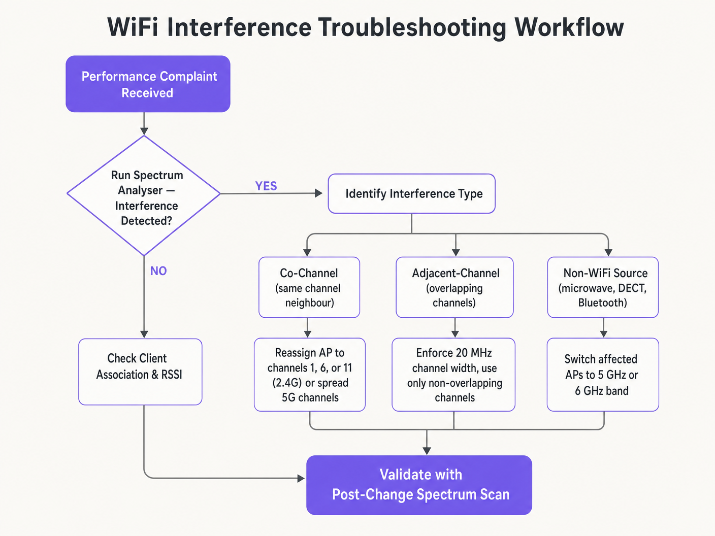
Before executing any configuration changes, understanding the physical layer of IEEE 802.11 networks is essential. The Radio Frequency (RF) spectrum is a shared medium governed by CSMA/CA (Carrier Sense Multiple Access with Collision Avoidance) protocols, and interference generally falls into two distinct categories: Co-Channel Interference (CCI) and Adjacent-Channel Interference (ACI).
Co-Channel Interference (CCI) occurs when multiple access points or clients transmit on the same channel. While the 802.11 protocol manages this using CSMA/CA—where devices listen before transmitting—excessive CCI forces devices to wait for clear-to-send times, drastically lowering throughput and increasing latency. This is essentially a congestion issue rather than true RF noise, and the CSMA/CA mechanism handles it gracefully up to a point.
Adjacent-Channel Interference (ACI) is far more destructive. This occurs when APs operate on overlapping frequencies (for example, Channels 2 and 4 on the 2.4 GHz band). Because the transmissions overlap but cannot be decoded by CSMA/CA, they are treated as pure noise, raising the noise floor and causing packet loss and retransmissions. In busy venues, ACI can degrade effective throughput by 60–70% and is the most common configuration error in enterprise deployments.
The 2.4 GHz Conundrum
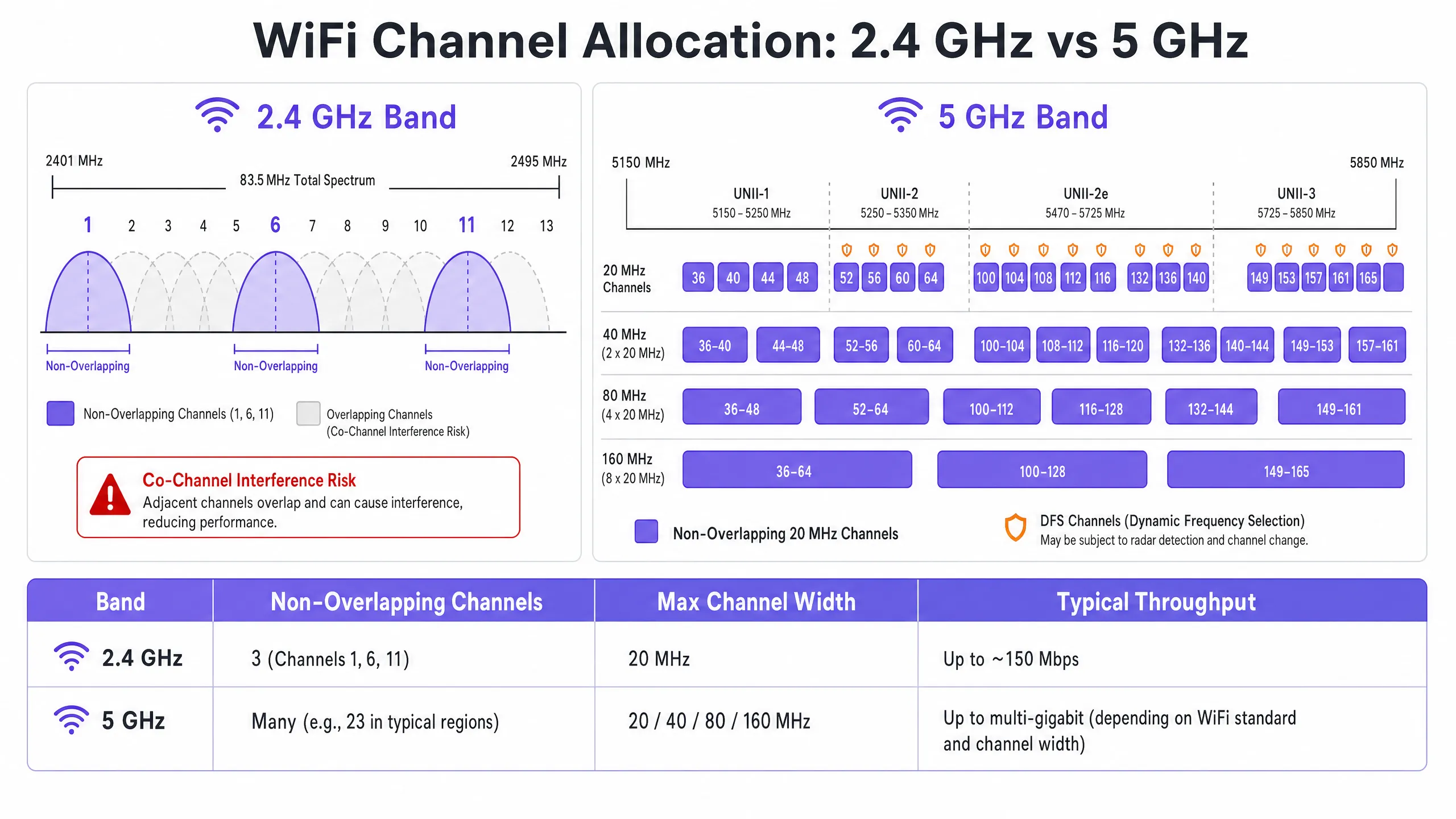
The 2.4 GHz band offers better range and wall penetration, but is severely limited by its narrow spectrum—approximately 83.5 MHz in total. While there are 11 to 14 channels available depending on the regulatory domain, only three are truly non-overlapping: Channels 1, 6, and 11. Using any other channel in a multi-AP deployment guarantees ACI. Additionally, this band is crowded with non-WiFi interferers, including Bluetooth devices, microwave ovens, and DECT cordless phones operating in the same spectrum. For a detailed analysis of how Bluetooth Low Energy coexists with WiFi infrastructure, see our guide Enterprise BLE Low Energy Decoded . For a broader treatment of band selection, see Wi-Fi Frequencies: The 2026 Guide to Wi-Fi Frequencies .
The 5 GHz Advantage
The 5 GHz band offers significantly more spectrum, providing an abundance of non-overlapping 20 MHz channels across UNII-1, UNII-2, UNII-2e, and UNII-3 sub-bands. This band is the correct default choice for enterprise client traffic. However, it introduces two critical complexities: channel-bonding trade-offs and Dynamic Frequency Selection (DFS).
Channel bonding—combining 20 MHz channels into 40, 80, or 160 MHz widths—increases peak throughput for a single client but reduces the total number of independent channels available. In high-density environments, this causes severe CCI. DFS channels (primarily UNII-2 and UNII-2e) require APs to monitor for radar signals and vacate the channel immediately if detected, causing client disconnections. This is a critical consideration for venues located near airports, weather stations, or military installations.
Implementation Playbook
Changing WiFi channels must never be based on guesswork. It requires a systematic, data-driven approach.
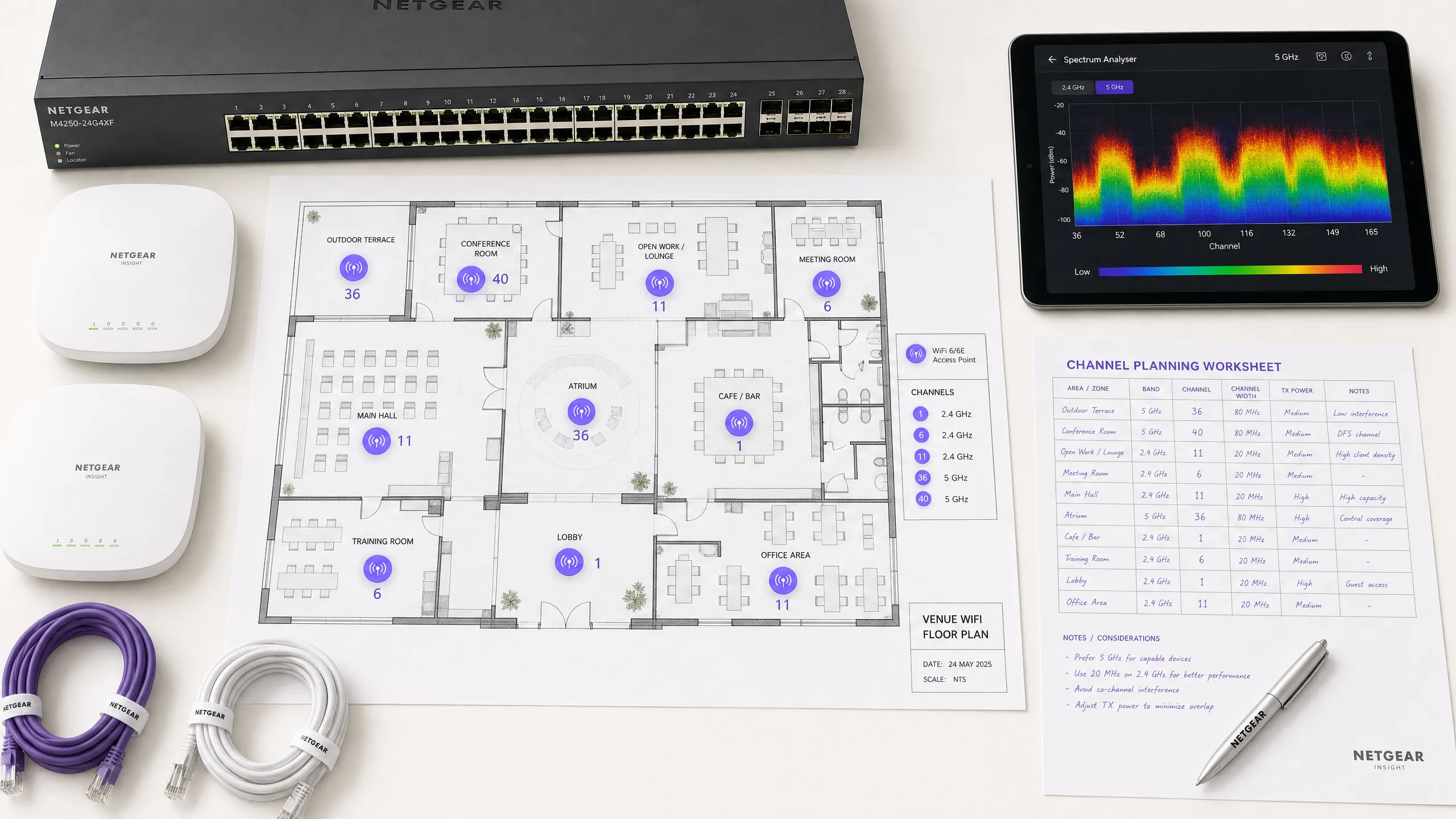
Step 1: Conduct a Spectrum Analysis
Before making any configuration changes, establish an empirical baseline. Deploy a spectrum analyser—either dedicated hardware or tools built into enterprise WLAN controllers—to survey the RF environment on both bands. Document the following: rogue or neighbouring APs and their channel allocations, the noise floor per channel, the presence of non-WiFi interferers, and current AP transmit power levels. This baseline is your reference point for measuring the impact of subsequent changes.
Step 2: Develop a Channel Plan
For the 2.4 GHz Band: Strictly limit your channel pool to Channels 1, 6, and 11. Set all channel widths to 20 MHz—this is non-negotiable. If AP density is high enough to cause significant CCI even with a 1-6-11 scheme, consider selectively disabling 2.4 GHz radios in a checkerboard pattern, effectively halving the 2.4 GHz AP density while maintaining coverage through remaining APs.
For the 5 GHz Band: Maximise the use of available non-overlapping channels. In high-density deployments—conference centres, stadiums, transport hubs—enforce 20 MHz channel widths to maximise the number of independent channels. Increase to 40 MHz only in low-density zones where CCI is not a concern. Carefully evaluate the inclusion of DFS channels depending on your specific location and proximity to radar sources. Consult your national regulatory authority's specific regional channel availability list.
Step 3: Configure the Access Points
Access your Wireless LAN Controller (WLC) or cloud management dashboard to apply your channel plan. Most enterprise platforms offer Radio Resource Management (RRM) or Auto-RF features that dynamically allocate channels and power levels.
| Methodology | Best For | Risks |
|---|---|---|
| Manual Static Planning | Complex, high-density, or radar-adjacent venues | Requires periodic resurveys as the environment changes |
| Auto-RF / RRM | Simpler, lower-density deployments | Can cause channel flapping in fluctuating RF environments |
| Hybrid Mode | Most enterprise deployments | Requires careful constraint configuration |
In highly complex environments, manual static channel planning based on predictive surveys often yields better stability than relying solely on Auto-RF. Transmit power must be tuned in parallel—lowering 5 GHz AP transmit power to 10–14 dBm in dense deployments to shrink cell sizes and reduce inter-AP interference.
Step 4: Verify and Monitor
After applying changes, conduct a post-implementation site survey to validate the new channel plan. Monitor Key Performance Indicators (KPIs) through your WiFi analytics platform, focusing on retry rates, airtime utilisation per AP, client association counts, and roaming behaviour. A well-tuned RF environment should display retry rates below 10% and airtime utilisation below 70% during peak periods.
Best Practices
Enforce 20 MHz width in high-density environments. In environments like conference centres or stadiums, prioritise capacity—more non-overlapping channels—over peak single-client throughput from wider channels. Overall network performance will improve significantly.
Actively implement band steering. Configure band steering to push 5 GHz-capable clients away from the congested 2.4 GHz band and towards 5 GHz. Most modern enterprise controllers support this natively. Reserve 2.4 GHz for IoT devices and legacy hardware that cannot operate on 5 GHz.
Disable legacy data rates. Disable 802.11b data rates (1, 2, 5.5, 11 Mbps) on all SSIDs. These legacy rates consume disproportionate airtime and slow down the entire network. Set the minimum data rate to 12 or 24 Mbps, forcing clients to roam earlier and reducing management frame overhead.
Schedule regular RF audits. RF environments are dynamic. New neighbouring networks, building renovations, and new devices all alter the interference landscape. Schedule quarterly RF audits to keep your channel plan up to date.
Integrate security and network management. Ensure rogue AP detection and mitigation are enabled to prevent unauthorised devices from causing interference or security vulnerabilities. For broader cybersecurity context, including content filtering on guest networks, consult What is DNS Filtering? How to Block Harmful Content on Guest WiFi . For office-specific optimisation strategies, see Office Wi-Fi: Optimising Your Modern Office Wi-Fi Network .
Troubleshooting & Risk Mitigation
Symptom: Strong signal strength, poor throughput. This is a hallmark of co-channel interference. The noise floor is low, but airtime is saturated. Audit channel assignments and AP transmit power. Lower transmit power and enforce 20 MHz channel widths to free up airtime and improve spatial reuse.
Symptom: Random client disconnections in specific areas. Check DFS event logs immediately. If APs in that area are on UNII-2 or UNII-2e channels and near a radar source, they are legally required to vacate the channel, causing client disconnections. Exclude those specific DFS channels from the channel plan in the affected area.
Symptom: Channel plan constantly changing automatically. This is channel flapping caused by an overly sensitive Auto-RF algorithm reacting to transient interference. Restrict RRM sensitivity settings, increase hold timers, or migrate to a static channel plan based on survey data.
Symptom: Good signal but poor performance in specific areas. Non-WiFi interference from microwave ovens, DECT phones, or industrial equipment may be raising the noise floor. A spectrum analyser will identify these sources. Remediation is to remove the source or migrate affected APs to the 5 GHz or 6 GHz bands, which are immune to most non-WiFi 2.4 GHz interference sources.
ROI & Business Impact
Optimising WiFi channels is a zero-cost infrastructure upgrade that yields immediate, measurable returns. Organisations that implement proper RF channel planning typically report a 30-40% reduction in WiFi-related helpdesk tickets within the first quarter. In healthcare environments, a well-tuned RF environment ensures the uninterrupted flow of critical telemetry data and supports compliance with clinical device communication requirements. In retail , it guarantees the seamless operation of mobile point-of-sale systems, accurate location analytics, and reliable inventory management applications.
From a CapEx perspective, correct channel planning often eliminates the perceived need for additional AP hardware. Many organisations that believe they have an AP density problem actually have a channel planning problem. It is standard practice to address RF configuration issues first—before procurement of additional hardware—during any rigorous network assessment. A well-tuned RF environment also extends the operational lifecycle of existing infrastructure, deferring expensive hardware refresh cycles and delivering an immediate, quantifiable return on existing capital investments.
Key Definitions
Co-Channel Interference (CCI)
Interference that occurs when multiple access points or client devices transmit on the exact same frequency channel simultaneously.
Managed by CSMA/CA, but causes congestion and reduced throughput when excessive. The primary symptom is high airtime utilisation with low throughput.
Adjacent-Channel Interference (ACI)
Interference caused by devices transmitting on overlapping but non-identical frequency channels, creating RF noise that CSMA/CA cannot decode or manage.
More destructive than CCI. Raises the noise floor, causes packet loss, and forces retransmissions. Caused by using channels other than 1, 6, and 11 on 2.4 GHz.
Dynamic Frequency Selection (DFS)
An IEEE 802.11h mechanism that requires WiFi access points to monitor for radar signals on certain 5 GHz channels and immediately vacate the channel if radar is detected.
Affects UNII-2 and UNII-2e channels. Critical consideration for venues near airports, weather stations, or military sites, where frequent radar detection causes client disconnections.
Radio Resource Management (RRM)
Automated algorithms within enterprise WLAN controllers that dynamically adjust channel assignments and transmit power levels based on real-time RF conditions.
Useful for adapting to changing RF environments, but can cause 'channel churn' — frequent channel changes — in volatile environments, disrupting client connectivity.
Channel Bonding
The process of combining multiple adjacent 20 MHz channels into wider 40, 80, or 160 MHz channels to increase peak single-client throughput.
Reduces the total number of available non-overlapping channels, increasing CCI risk in dense deployments. Should be avoided in high-density enterprise environments.
Band Steering
A WLAN controller feature that encourages dual-band capable client devices to associate with the 5 GHz band rather than the congested 2.4 GHz band.
Essential for load balancing in enterprise deployments. Preserves the limited 2.4 GHz spectrum for IoT devices and legacy hardware that cannot operate on 5 GHz.
CSMA/CA
Carrier Sense Multiple Access with Collision Avoidance. The medium access control protocol used by IEEE 802.11 WiFi, requiring devices to listen for clear airtime before transmitting.
The mechanism that governs how WiFi devices share the RF medium. High CCI forces devices to wait longer for clear airtime, directly reducing throughput and increasing latency.
Noise Floor
The aggregate level of background RF energy present in a given frequency band, measured in dBm. A higher noise floor reduces the effective Signal-to-Noise Ratio (SNR) for WiFi transmissions.
Raised by ACI, non-WiFi interference, and poor channel planning. A high noise floor forces devices to use lower modulation schemes and data rates, reducing throughput.
Spatial Reuse
The ability of multiple access points to simultaneously transmit on the same channel without interfering with each other, enabled by physical separation and appropriate transmit power levels.
The fundamental mechanism that allows high-density WiFi networks to scale. Maximised by reducing AP transmit power and using the minimum necessary channel widths.
Worked Examples
A 200-room hotel is experiencing widespread complaints of slow WiFi during the evening peak. The current deployment uses 40 MHz channels on the 2.4 GHz band across 80 APs, and Auto-RF is enabled. The WLAN controller logs show frequent channel changes throughout the evening.
Phase 1 — Immediate remediation: Reconfigure all 2.4 GHz radios to 20 MHz channel widths immediately. Restrict the 2.4 GHz channel pool to channels 1, 6, and 11 only within the controller. This alone will eliminate ACI across the deployment.
Phase 2 — Stabilise Auto-RF: Review the Auto-RF event logs. If APs are changing channels more than once per hour, the algorithm is reacting to transient interference. Increase the RRM hold-down timer and reduce the sensitivity threshold. If churn persists, migrate to a static channel plan.
Phase 3 — Band steering: Enable aggressive band steering to push dual-band devices to 5 GHz. This reduces 2.4 GHz load significantly during peak periods.
Phase 4 — Validation: Deploy a spectrum analyser post-change and monitor retry rates and airtime utilisation via the WiFi analytics dashboard for 48 hours to confirm improvement.
A large retail chain has deployed APs every 12 metres across a 4,000 sq metre distribution centre. Even on the 5 GHz band using 20 MHz channels, CCI is high, throughput is poor, and mobile scanning devices are experiencing frequent disconnections during peak shift hours.
Step 1 — Audit transmit power: The APs are almost certainly configured at maximum TX power (typically 20–23 dBm). At 12-metre spacing, this creates massive cell overlap. Reduce TX power to 10–12 dBm on 5 GHz to shrink cell sizes and reduce inter-AP interference.
Step 2 — Disable legacy data rates: Disable all 802.11b/g data rates below 12 Mbps. This forces scanning devices to roam to the nearest AP rather than staying associated with a distant AP at a low data rate, which consumes disproportionate airtime.
Step 3 — Review channel plan: Ensure the 5 GHz channel plan uses the maximum number of non-overlapping channels available. With high AP density, every unique channel matters.
Step 4 — Validate with post-change survey: Conduct a walkthrough survey with a spectrum analyser to confirm reduced inter-AP overlap and improved SNR across the floor.
Practice Questions
Q1. You are deploying a new wireless network in a multi-tenant office building. Your spectrum scan shows heavy utilisation on channels 1, 6, and 11 from neighbouring tenants. A junior engineer suggests using channels 3, 8, and 13 to 'avoid the congestion'. How do you respond, and what is the correct configuration?
Hint: Consider the difference between Co-Channel Interference (CCI) and Adjacent-Channel Interference (ACI), and which is more harmful to network performance.
View model answer
The junior engineer's suggestion is incorrect and would cause severe performance degradation. Channels 3, 8, and 13 overlap with channels 1, 6, and 11 respectively, which would introduce Adjacent-Channel Interference — the most destructive form of WiFi interference. ACI manifests as pure RF noise that CSMA/CA cannot manage, causing packet loss and retransmissions. The correct configuration is to deploy on channels 1, 6, and 11. While this will cause Co-Channel Interference with the neighbouring tenants, CSMA/CA can handle CCI gracefully by having devices take turns. The aggregate performance will be significantly better than with ACI.
Q2. A stadium deployment is using 80 MHz channels on the 5 GHz band to advertise 'Gigabit WiFi' speeds during events. Users report slow loading times, frequent disconnections, and poor video streaming quality during peak occupancy. The AP hardware is modern WiFi 6 equipment. What is the architectural flaw, and what is the remediation?
Hint: Evaluate the trade-off between peak single-client throughput and overall network capacity in a high-density environment.
View model answer
The architectural flaw is the use of 80 MHz channel widths in a high-density environment. Each 80 MHz channel bonds four 20 MHz channels together, drastically reducing the total number of non-overlapping channels available across the deployment. With many APs forced to reuse the same wide channels, Co-Channel Interference becomes severe. The solution is to reduce channel widths to 20 MHz across all APs. This increases the number of independent channels available, reduces CCI, and significantly improves aggregate network capacity. The peak throughput per client will decrease, but the number of clients that can be served simultaneously — and the quality of their experience — will increase substantially.
Q3. Your hospital network experiences intermittent client disconnections affecting medical devices in wards near the hospital's rooftop helipad. The affected APs are configured to use channels 52, 56, 60, and 64. What is the most likely cause, and what is the correct remediation?
Hint: Consider the regulatory requirements for the specific 5 GHz channels in use and what systems operate near a helipad.
View model answer
Channels 52, 56, 60, and 64 are UNII-2 DFS channels. The helicopters using the helipad, or associated aviation radar systems, are likely triggering DFS radar detection events on the APs in that zone. When radar is detected, the APs are legally required to immediately vacate those channels, causing client disconnections. The correct remediation is to exclude all DFS channels from the channel plan for APs in the zones near the helipad. Reconfigure those APs to use UNII-1 channels (36, 40, 44, 48) or UNII-3 channels (149, 153, 157, 161, 165), which are not subject to DFS requirements.
Continue reading in this series
Understanding RSSI and Signal Strength for Optimal Channel Planning
This guide provides a comprehensive technical deep-dive into RSSI, Signal-to-Noise Ratio (SNR), and RF propagation principles for optimal channel planning. It equips IT managers, network architects, and venue operations directors with actionable strategies to mitigate Co-Channel and Adjacent Channel Interference, optimise AP placement, and leverage analytics for measurable business impact across hospitality, retail, and public-sector environments.
20MHz vs 40MHz vs 80MHz: Which Channel Width Should You Use?
This guide provides a definitive, vendor-neutral technical reference for IT managers, network architects, and venue operations directors on selecting the correct WiFi channel width — 20MHz, 40MHz, or 80MHz — across enterprise deployments in hospitality, retail, events, and public-sector environments. It covers the underlying IEEE 802.11 mechanics, real-world capacity trade-offs, and step-by-step deployment guidance to help teams make the right call this quarter. Understanding channel width selection is one of the highest-leverage decisions in any wireless LAN design, directly impacting throughput, interference, client density support, and the reliability of guest-facing services.