How to Change WiFi Channels to Prevent Interference
This comprehensive technical guide provides IT managers, network architects, and venue operations directors with a definitive, step-by-step approach to identifying WiFi interference sources and strategically changing WiFi channels to eliminate them. It covers 2.4 GHz and 5 GHz band planning, spectrum analysis, Radio Resource Management, and DFS considerations, grounded in IEEE 802.11 standards and real-world deployment scenarios. Implementing these strategies delivers measurable improvements in network throughput, client stability, and infrastructure ROI without requiring capital expenditure on new hardware.
Listen to this guide
View podcast transcript
概要
对于企业环境——从广阔的 酒店业 场所到密集的 零售业 空间——可靠的WiFi已不再是额外福利,而是关键基础设施。干扰仍然是导致连接中断、高延迟和吞吐量低下的首要原因,直接影响运营效率和 宾客WiFi 体验。本指南为网络架构师和IT经理提供了一种确定的、分步的方法,用于识别干扰源并战略性地更改WiFi信道以减轻干扰。
通过实施供应商中立的频谱管理最佳实践,组织可以最大化其基础设施投资回报率,确保无缝的客户端漫游,并支持不断增长的物联网和用户设备密度,同时不损害安全性或合规性标准,包括PCI DSS和GDPR。核心原则很简单:干扰是频谱管理问题,而非硬件问题。正确配置现有基础设施在大多数情况下可以解决组织错误地归因于AP密度不足或设备过时的性能问题。
技术深度剖析
在进行任何配置更改之前,理解IEEE 802.11网络的物理层至关重要。无线电频率(RF)频谱是一种共享介质,受CSMA/CA(载波侦听多路访问/冲突避免)协议控制,干扰通常分为两种不同类型:同信道干扰(CCI)和邻信道干扰(ACI)。
**同信道干扰(CCI)**发生在多个接入点或客户端在同一信道上传输时。虽然802.11协议使用CSMA/CA来管理这一点——设备在传输前进行侦听——但过度的CCI迫使设备等待空闲的发送时间,急剧降低吞吐量并增加延迟。这本质上是拥塞问题而不是真正的RF噪声,CSMA/CA机制可以在一定程度上优雅地处理它。
**邻信道干扰(ACI)**破坏性要大得多。当AP在重叠频率上运行时(例如,在2.4 GHz频段上的信道2和4),就会发生这种情况。由于传输重叠但无法被CSMA/CA解码,它们被视为纯噪声,抬高本底噪声并导致数据包丢失和重传。在繁忙的场所,ACI可将有效吞吐量降低60-70%,是企业部署中最常见的配置错误。
2.4 GHz的难题
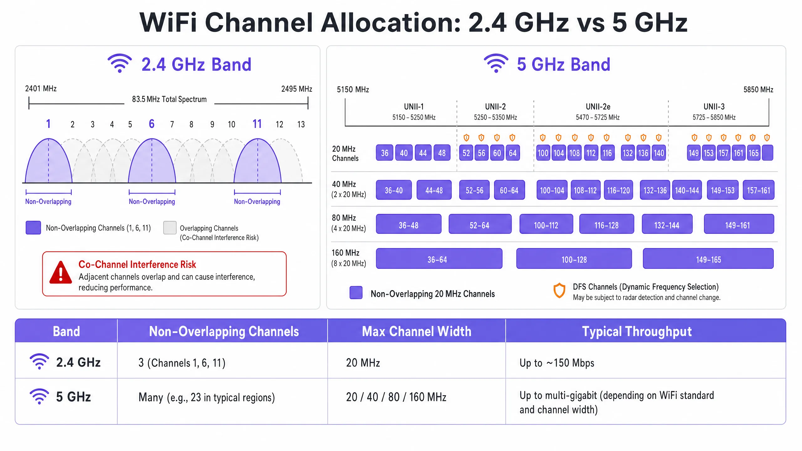
2.4 GHz频段提供更好的覆盖范围和墙壁穿透能力,但受到有限频谱的严重限制——总共约83.5 MHz。尽管根据监管域不同有11到14个信道,但真正不重叠的只有三个:信道1、6和11。在多AP部署中使用任何其他信道都会保证产生ACI。此外,该频段挤满了非WiFi干扰源,包括蓝牙设备、微波炉和在同一频谱中运行的DECT无绳电话。有关蓝牙低功耗如何与WiFi基础设施共存的详细分析,请参阅我们的指南 企业级BLE低功耗解析 。有关频段选择的更广泛处理,请参阅 Wi-Fi频率:2026年Wi-Fi频率指南 。
5 GHz的优势
5 GHz频段提供显著更多的频谱,在UNII-1、UNII-2、UNII-2e和UNII-3子频段中提供大量不重叠的20 MHz信道。该频段是企业客户端流量的正确默认选择。然而,它引入了两个关键复杂性:信道绑定权衡和动态频率选择(DFS)。
信道绑定——将20 MHz信道组合成40、80或160 MHz宽度——提高了单客户端的峰值吞吐量,但减少了可用的独立信道总数。在高密度环境中,这会导致严重的CCI。DFS信道(主要是UNII-2和UNII-2e)要求AP监控雷达信号,并在检测到时立即腾出信道,导致客户端断开连接。这对于靠近机场、气象站或军事设施的场所是一个关键考虑因素。
实施指南
更改WiFi信道绝不应基于猜测。它需要一种系统的、数据驱动的方法。
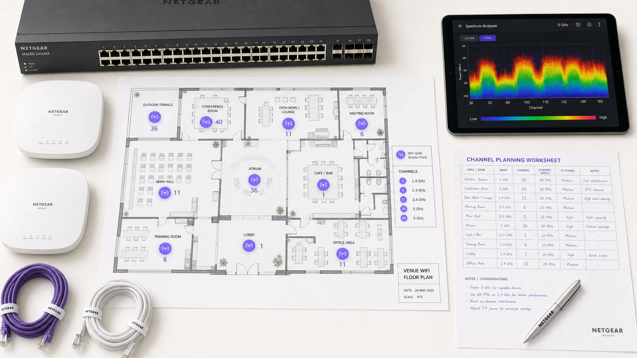
步骤1:进行频谱分析
在进行任何配置更改之前,建立经验性的基准。部署频谱分析仪——无论是专用硬件还是企业WLAN控制器内置工具——在两大频段上勘察RF环境。记录以下内容:非法或邻近AP及其信道分配、每个信道的本底噪声、非WiFi干扰源的存在以及当前AP发射功率水平。此基准是测量后续更改影响的参考点。
步骤2:制定信道计划
**对于2.4 GHz频段:**严格将信道池限制为信道1、6和11。将所有信道宽度设置为20 MHz——这是不可协商的。如果AP密度高到即使在1-6-11方案下也会导致显著的CCI,考虑以棋盘模式交替禁用2.4 GHz无线电,有效地将2.4 GHz AP密度减半,同时通过其余AP保持覆盖。
**对于5 GHz频段:**最大化使用可用的不重叠信道。在高密度部署中——会议中心、体育场、 交通 枢纽——强制执行20 MHz信道宽度,以最大化独立信道数量。仅在CCI不令人担忧的低密度区域增加到40 MHz。根据您的具体位置和与雷达源的接近程度,仔细评估DFS信道的包含。请查阅您国家监管机构的特定区域信道可用性列表。
步骤3:配置接入点
访问您的无线LAN控制器(WLC)或云管理仪表板以应用信道计划。大多数企业平台提供无线电资源管理(RRM)或Auto-RF功能,可动态分配信道和功率水平。
| 方法 | 最适合 | 风险 |
|---|---|---|
| 手动静态计划 | 复杂、高密度或靠近雷达的场所 | 需要随着环境变化进行定期重新勘测 |
| 自动RF / RRM | 更简单、低密度部署 | 在波动的RF环境中可能导致信道抖动 |
| 混合模式 | 大多数企业部署 | 需要谨慎的约束配置 |
在高度复杂的环境中,基于预测性勘测的手动静态信道计划通常比仅依赖Auto-RF产生更好的稳定性。必须并行调整发射功率——在密集部署中将5 GHz的AP发射功率降低到10–14 dBm,以缩小小区大小并减少AP间干扰。
步骤4:验证与监控
应用更改后,进行实施后的现场勘测以验证新的信道计划。通过您的 WiFi分析 平台监控关键绩效指标(KPI),重点关注重试率、每个AP的发送时间利用率、客户端关联计数和漫游行为。一个调优良好的RF环境应在高峰期间显示重试率低于10%和发送时间利用率低于70%。
最佳实践
**在高密度环境中强制执行20 MHz宽度。**在会议中心或体育场等环境中,优先考虑容量——更多的不重叠信道——而不是来自更宽信道的峰值单客户端吞吐量。总体网络性能将显著提高。
**积极实施频段引导。**配置频段引导,将支持5 GHz的客户端从拥挤的2.4 GHz频段推向5 GHz。大多数现代企业控制器原生支持此功能。将2.4 GHz保留给无法在5 GHz上运行的物联网设备和旧硬件。
**禁用旧数据速率。**在所有SSID上禁用802.11b数据速率(1、2、5.5、11 Mbps)。这些旧速率消耗不成比例的发送时间并减慢整个网络。将最低数据速率设置为12或24 Mbps,迫使客户端更早漫游并减少管理帧开销。
**安排定期的RF审计。**RF环境是动态的。新的邻近网络、建筑改造和新设备都会改变干扰格局。每季度安排RF审计,以保持您的信道计划最新。
**集成安全和网络管理。**确保启用非法AP检测和缓解,以防止未经授权的设备造成干扰或安全漏洞。有关更广泛的网络安全背景,包括访客网络上的内容过滤,请查阅 什么是DNS过滤?如何在宾客WiFi上阻止有害内容 。有关办公室特定的优化策略,请参阅 办公室Wi-Fi:优化您的现代办公室Wi-Fi网络 。
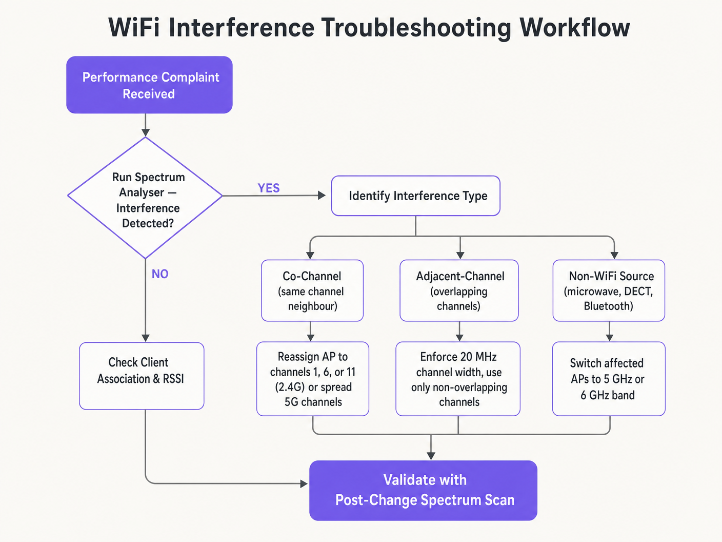
故障排除与风险缓解
**症状:信号强,吞吐量差。**这是同信道干扰的标志。本底噪声低但发送时间饱和。审计信道分配和AP发射功率。降低发射功率并强制执行20 MHz信道宽度,以释放发送时间并改善空间复用。
**症状:特定区域随机客户端断开连接。**立即检查DFS事件日志。如果该区域的AP位于UNII-2或UNII-2e信道上且靠近雷达源,则法律要求它们腾出信道,导致客户端断开连接。从受影响区域的信道计划中排除这些特定的DFS信道。
**症状:信道计划不断自动更改。**这是由于过于敏感的Auto-RF算法对瞬态干扰做出反应而导致的信道抖动。限制RRM灵敏度设置,增加保持计时器,或迁移到基于勘测数据的静态信道计划。
**症状:特定区域信号良好但性能差。**来自微波炉、DECT电话或工业设备的非WiFi干扰可能正在抬高本底噪声。频谱分析仪将识别这些来源。补救措施是移除干扰源或将受影响的AP迁移到5 GHz或6 GHz频段,这些频段对大多数非WiFi 2.4 GHz干扰源免疫。
投资回报率与业务影响
优化WiFi信道是一项零成本的基础设施升级,可带来即时的、可衡量的回报。实施适当RF信道规划的组织通常报告在第一个季度内与WiFi相关的帮助台工单减少了30-40%。在 医疗保健 环境中,调优良好的RF环境可确保关键遥测数据的不间断流动,并支持符合临床设备通信要求。在 零售业 中,它保证了移动销售点系统的无缝运行、准确的位置分析和可靠的库存管理应用程序。
从资本支出的角度来看,正确的信道规划通常消除了对额外AP硬件的感知需求。许多认为自己存在AP密度问题的组织实际上存在信道规划问题。在进行任何严格的网络评估时,首先解决RF配置问题——在采购额外硬件之前——是标准做法。调优良好的RF环境还可以延长现有基础设施的运行生命周期,推迟昂贵的硬件更新周期,并为现有资本投资带来直接的、可量化的回报。
Key Definitions
Co-Channel Interference (CCI)
Interference that occurs when multiple access points or client devices transmit on the exact same frequency channel simultaneously.
Managed by CSMA/CA, but causes congestion and reduced throughput when excessive. The primary symptom is high airtime utilisation with low throughput.
Adjacent-Channel Interference (ACI)
Interference caused by devices transmitting on overlapping but non-identical frequency channels, creating RF noise that CSMA/CA cannot decode or manage.
More destructive than CCI. Raises the noise floor, causes packet loss, and forces retransmissions. Caused by using channels other than 1, 6, and 11 on 2.4 GHz.
Dynamic Frequency Selection (DFS)
An IEEE 802.11h mechanism that requires WiFi access points to monitor for radar signals on certain 5 GHz channels and immediately vacate the channel if radar is detected.
Affects UNII-2 and UNII-2e channels. Critical consideration for venues near airports, weather stations, or military sites, where frequent radar detection causes client disconnections.
Radio Resource Management (RRM)
Automated algorithms within enterprise WLAN controllers that dynamically adjust channel assignments and transmit power levels based on real-time RF conditions.
Useful for adapting to changing RF environments, but can cause 'channel churn' — frequent channel changes — in volatile environments, disrupting client connectivity.
Channel Bonding
The process of combining multiple adjacent 20 MHz channels into wider 40, 80, or 160 MHz channels to increase peak single-client throughput.
Reduces the total number of available non-overlapping channels, increasing CCI risk in dense deployments. Should be avoided in high-density enterprise environments.
Band Steering
A WLAN controller feature that encourages dual-band capable client devices to associate with the 5 GHz band rather than the congested 2.4 GHz band.
Essential for load balancing in enterprise deployments. Preserves the limited 2.4 GHz spectrum for IoT devices and legacy hardware that cannot operate on 5 GHz.
CSMA/CA
Carrier Sense Multiple Access with Collision Avoidance. The medium access control protocol used by IEEE 802.11 WiFi, requiring devices to listen for clear airtime before transmitting.
The mechanism that governs how WiFi devices share the RF medium. High CCI forces devices to wait longer for clear airtime, directly reducing throughput and increasing latency.
Noise Floor
The aggregate level of background RF energy present in a given frequency band, measured in dBm. A higher noise floor reduces the effective Signal-to-Noise Ratio (SNR) for WiFi transmissions.
Raised by ACI, non-WiFi interference, and poor channel planning. A high noise floor forces devices to use lower modulation schemes and data rates, reducing throughput.
Spatial Reuse
The ability of multiple access points to simultaneously transmit on the same channel without interfering with each other, enabled by physical separation and appropriate transmit power levels.
The fundamental mechanism that allows high-density WiFi networks to scale. Maximised by reducing AP transmit power and using the minimum necessary channel widths.
Worked Examples
A 200-room hotel is experiencing widespread complaints of slow WiFi during the evening peak. The current deployment uses 40 MHz channels on the 2.4 GHz band across 80 APs, and Auto-RF is enabled. The WLAN controller logs show frequent channel changes throughout the evening.
Phase 1 — Immediate remediation: Reconfigure all 2.4 GHz radios to 20 MHz channel widths immediately. Restrict the 2.4 GHz channel pool to channels 1, 6, and 11 only within the controller. This alone will eliminate ACI across the deployment.
Phase 2 — Stabilise Auto-RF: Review the Auto-RF event logs. If APs are changing channels more than once per hour, the algorithm is reacting to transient interference. Increase the RRM hold-down timer and reduce the sensitivity threshold. If churn persists, migrate to a static channel plan.
Phase 3 — Band steering: Enable aggressive band steering to push dual-band devices to 5 GHz. This reduces 2.4 GHz load significantly during peak periods.
Phase 4 — Validation: Deploy a spectrum analyser post-change and monitor retry rates and airtime utilisation via the WiFi analytics dashboard for 48 hours to confirm improvement.
A large retail chain has deployed APs every 12 metres across a 4,000 sq metre distribution centre. Even on the 5 GHz band using 20 MHz channels, CCI is high, throughput is poor, and mobile scanning devices are experiencing frequent disconnections during peak shift hours.
Step 1 — Audit transmit power: The APs are almost certainly configured at maximum TX power (typically 20–23 dBm). At 12-metre spacing, this creates massive cell overlap. Reduce TX power to 10–12 dBm on 5 GHz to shrink cell sizes and reduce inter-AP interference.
Step 2 — Disable legacy data rates: Disable all 802.11b/g data rates below 12 Mbps. This forces scanning devices to roam to the nearest AP rather than staying associated with a distant AP at a low data rate, which consumes disproportionate airtime.
Step 3 — Review channel plan: Ensure the 5 GHz channel plan uses the maximum number of non-overlapping channels available. With high AP density, every unique channel matters.
Step 4 — Validate with post-change survey: Conduct a walkthrough survey with a spectrum analyser to confirm reduced inter-AP overlap and improved SNR across the floor.
Practice Questions
Q1. You are deploying a new wireless network in a multi-tenant office building. Your spectrum scan shows heavy utilisation on channels 1, 6, and 11 from neighbouring tenants. A junior engineer suggests using channels 3, 8, and 13 to 'avoid the congestion'. How do you respond, and what is the correct configuration?
Hint: Consider the difference between Co-Channel Interference (CCI) and Adjacent-Channel Interference (ACI), and which is more harmful to network performance.
View model answer
The junior engineer's suggestion is incorrect and would cause severe performance degradation. Channels 3, 8, and 13 overlap with channels 1, 6, and 11 respectively, which would introduce Adjacent-Channel Interference — the most destructive form of WiFi interference. ACI manifests as pure RF noise that CSMA/CA cannot manage, causing packet loss and retransmissions. The correct configuration is to deploy on channels 1, 6, and 11. While this will cause Co-Channel Interference with the neighbouring tenants, CSMA/CA can handle CCI gracefully by having devices take turns. The aggregate performance will be significantly better than with ACI.
Q2. A stadium deployment is using 80 MHz channels on the 5 GHz band to advertise 'Gigabit WiFi' speeds during events. Users report slow loading times, frequent disconnections, and poor video streaming quality during peak occupancy. The AP hardware is modern WiFi 6 equipment. What is the architectural flaw, and what is the remediation?
Hint: Evaluate the trade-off between peak single-client throughput and overall network capacity in a high-density environment.
View model answer
The architectural flaw is the use of 80 MHz channel widths in a high-density environment. Each 80 MHz channel bonds four 20 MHz channels together, drastically reducing the total number of non-overlapping channels available across the deployment. With many APs forced to reuse the same wide channels, Co-Channel Interference becomes severe. The solution is to reduce channel widths to 20 MHz across all APs. This increases the number of independent channels available, reduces CCI, and significantly improves aggregate network capacity. The peak throughput per client will decrease, but the number of clients that can be served simultaneously — and the quality of their experience — will increase substantially.
Q3. Your hospital network experiences intermittent client disconnections affecting medical devices in wards near the hospital's rooftop helipad. The affected APs are configured to use channels 52, 56, 60, and 64. What is the most likely cause, and what is the correct remediation?
Hint: Consider the regulatory requirements for the specific 5 GHz channels in use and what systems operate near a helipad.
View model answer
Channels 52, 56, 60, and 64 are UNII-2 DFS channels. The helicopters using the helipad, or associated aviation radar systems, are likely triggering DFS radar detection events on the APs in that zone. When radar is detected, the APs are legally required to immediately vacate those channels, causing client disconnections. The correct remediation is to exclude all DFS channels from the channel plan for APs in the zones near the helipad. Reconfigure those APs to use UNII-1 channels (36, 40, 44, 48) or UNII-3 channels (149, 153, 157, 161, 165), which are not subject to DFS requirements.
Continue reading in this series
Understanding RSSI and Signal Strength for Optimal Channel Planning
This guide provides a comprehensive technical deep-dive into RSSI, Signal-to-Noise Ratio (SNR), and RF propagation principles for optimal channel planning. It equips IT managers, network architects, and venue operations directors with actionable strategies to mitigate Co-Channel and Adjacent Channel Interference, optimise AP placement, and leverage analytics for measurable business impact across hospitality, retail, and public-sector environments.
20MHz vs 40MHz vs 80MHz: Which Channel Width Should You Use?
This guide provides a definitive, vendor-neutral technical reference for IT managers, network architects, and venue operations directors on selecting the correct WiFi channel width — 20MHz, 40MHz, or 80MHz — across enterprise deployments in hospitality, retail, events, and public-sector environments. It covers the underlying IEEE 802.11 mechanics, real-world capacity trade-offs, and step-by-step deployment guidance to help teams make the right call this quarter. Understanding channel width selection is one of the highest-leverage decisions in any wireless LAN design, directly impacting throughput, interference, client density support, and the reliability of guest-facing services.