Understanding WiFi Speed Meaning: Throughput vs Bandwidth
This authoritative technical reference guide demystifies WiFi speed metrics for enterprise IT leaders, clearly distinguishing between link speed, bandwidth, and throughput. It provides actionable methodologies for measuring real-world performance, mitigating RF congestion, and optimising WLAN infrastructure across high-density venue deployments. IT managers, network architects, and venue operations directors will leave with concrete frameworks for aligning infrastructure investments with measurable business outcomes.
Listen to this guide
View podcast transcript

कार्यकारी सारांश
एंटरप्राइज WLAN तैनात करने वाले IT प्रबंधकों और नेटवर्क आर्किटेक्ट्स के लिए, विज्ञापित WiFi स्पीड और वास्तविक उपयोगकर्ता अनुभव के बीच का अंतर एक निरंतर परिचालन चुनौती है। इसका मुख्य कारण लगभग हमेशा तीन अलग-अलग मेट्रिक्स की गलत समझ होती है: लिंक स्पीड (PHY रेट), बैंडविड्थ और थ्रूपुट। जबकि वेंडर अधिकतम सैद्धांतिक लिंक स्पीड का विपणन करते हैं — उदाहरण के लिए, 802.11ax पर 1200 Mbps — प्रोटोकॉल ओवरहेड, हाफ-डुप्लेक्स रेडियो संचालन और पर्यावरणीय प्रतिस्पर्धा के कारण किसी एप्लिकेशन को मिलने वाला वास्तविक थ्रूपुट आमतौर पर उस आंकड़े का 40-60% होता है।
यह तकनीकी संदर्भ मार्गदर्शिका एंटरप्राइज वातावरण में WiFi स्पीड का अर्थ समझने के लिए एक निश्चित ढांचा प्रदान करती है। यह होटलों, रिटेल चेन और बड़े स्थानों पर IT टीमों को वास्तविक दुनिया के प्रदर्शन को सटीक रूप से मापने, कवरेज के बजाय क्षमता के लिए डिजाइन करने और मापने योग्य व्यावसायिक परिणामों के साथ बुनियादी ढांचे के निवेश को संरेखित करने के ज्ञान से लैस करता है। सैद्धांतिक अधिकतम सीमाओं से ध्यान हटाकर निरंतर थ्रूपुट और इष्टतम बैंडविड्थ आवंटन पर केंद्रित करके, वेन्यू ऑपरेटर वह विश्वसनीय कनेक्टिविटी प्रदान कर सकते हैं जिसकी आधुनिक गेस्ट WiFi और WiFi एनालिटिक्स प्लेटफॉर्म मांग करते हैं।
तकनीकी गहन विश्लेषण: WiFi स्पीड मेट्रिक्स को डिकोड करना
एक मजबूत WLAN को इंजीनियर करने के लिए, IT पेशेवरों को RF माध्यम की सैद्धांतिक क्षमताओं और डेटा पेलोड की व्यावहारिक डिलीवरी के बीच अंतर करना चाहिए। तीन मेट्रिक्स — लिंक स्पीड, बैंडविड्थ और थ्रूपुट — को अक्सर वेंडर मार्केटिंग, खरीद चर्चाओं और यहां तक कि आंतरिक IT रिपोर्टिंग में मिला दिया जाता है। इसे सही ढंग से समझना हर दूसरे अनुकूलन निर्णय के लिए बुनियादी है।
लिंक स्पीड (PHY रेट): सैद्धांतिक सीमा
लिंक स्पीड, या फिजिकल लेयर (PHY) रेट, रेडियो स्तर पर एक एक्सेस पॉइंट (AP) और एक क्लाइंट डिवाइस के बीच अधिकतम सैद्धांतिक डेटा ट्रांसफर दर का प्रतिनिधित्व करता है। यह दर एसोसिएशन के समय मॉड्यूलेशन और कोडिंग स्कीम (MCS), स्पेशल स्ट्रीम की संख्या और सिग्नल-टू-नॉइज़ रेशियो (SNR) के आधार पर गतिशील रूप से तय की जाती है।
महत्वपूर्ण रूप से, लिंक स्पीड व्यावहारिक रूप से कभी भी प्राप्त करने योग्य नहीं होती है। यह सकल बिट दर का प्रतिनिधित्व करती है, जिसमें सभी 802.11 प्रबंधन फ्रेम, नियंत्रण फ्रेम (RTS/CTS और ACK), और इंटर-फ्रेम स्पेसिंग (AIFS/DIFS) शामिल हैं। रिटेल या हॉस्पिटैलिटी वातावरण में एंटरप्राइज परिनियोजन में, 802.11ac नेटवर्क पर 866 Mbps लिंक स्पीड की रिपोर्ट करने वाला क्लाइंट वास्तव में आदर्श, अलग परिस्थितियों में लगभग 400-500 Mbps वास्तविक डेटा ट्रांसफर करने में सक्षम होता है — और साझा, मल्टी-क्लाइंट वातावरण में इससे बहुत कम।
बैंडविड्थ: RF चैनल क्षमता
बैंडविड्थ से तात्पर्य ट्रांसमिशन के लिए आवंटित रेडियो फ्रीक्वेंसी चैनल की चौड़ाई से है, जिसे आमतौर पर मेगाहर्ट्ज़ (MHz) में मापा जाता है। 5 GHz और 6 GHz बैंड में, चैनल 20, 40, 80 या 160 MHz चौड़े हो सकते हैं। व्यापक चैनल उच्च संभावित लिंक स्पीड प्रदान करते हैं — चैनल की चौड़ाई को दोगुना करने से संभावित डेटा दर लगभग दोगुनी हो जाती है — लेकिन वे प्रति दोगुना होने पर नॉइज़ फ्लोर को 3 dB बढ़ा देते हैं और उपलब्ध नॉन-ओवरलैपिंग चैनलों की संख्या को काफी कम कर देते हैं।
स्टेडियम, कॉन्फ्रेंस सेंटर या होटल के गलियारों जैसे उच्च-घनत्व वाले वातावरण में, 80 MHz चैनलों को तैनात करने से अक्सर विनाशकारी को-चैनल इंटरफेरेंस (CCI) होता है। इसलिए एंटरप्राइज सर्वोत्तम अभ्यास व्यक्तिगत चरम स्पीड का पीछा करने के बजाय स्पेक्ट्रल पुनरुपयोग और समग्र सिस्टम क्षमता को अधिकतम करने के लिए 20 MHz या 40 MHz चैनलों का उपयोग करने का निर्देश देता है। यह एक ऐसी डिजाइन फिलॉसफी है जो किसी भी एकल उपयोगकर्ता के लिए सैद्धांतिक अधिकतम के बजाय सभी उपयोगकर्ताओं के कुल थ्रूपुट को प्राथमिकता देती है।
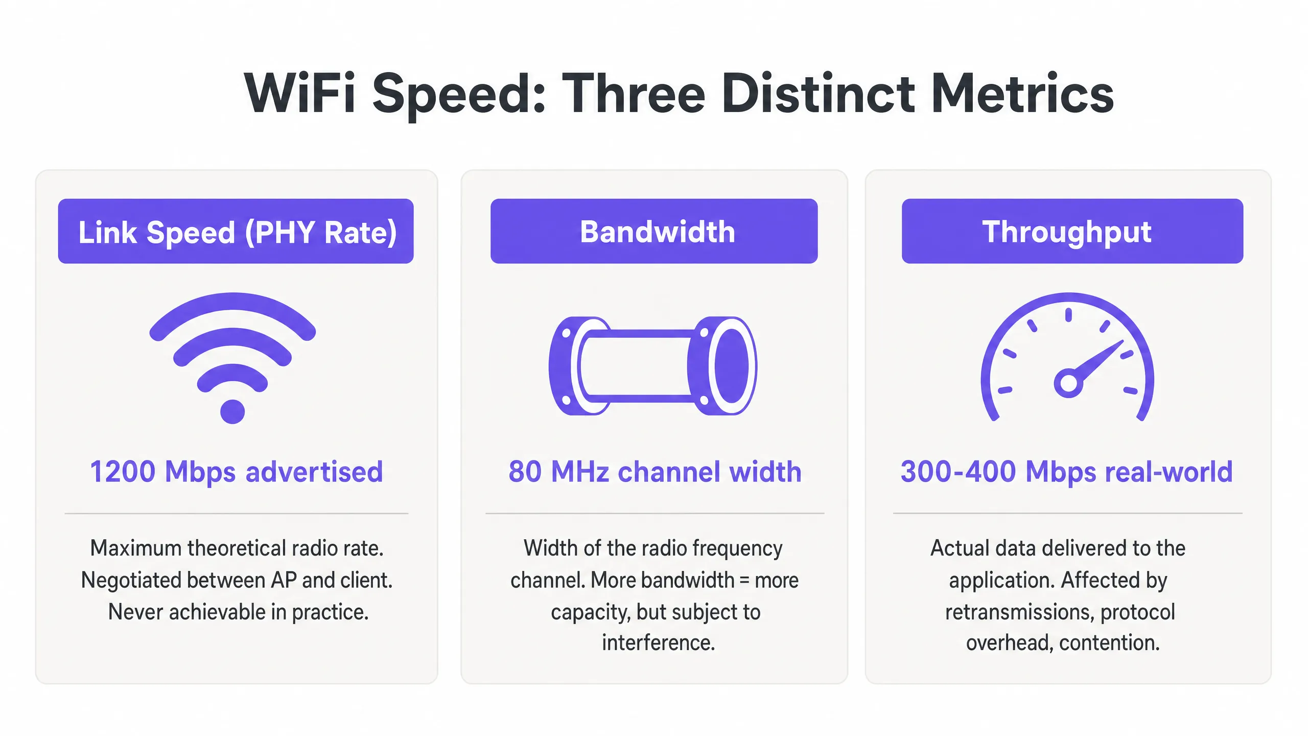
थ्रूपुट: वास्तविक दुनिया का मापन
थ्रूपुट वास्तव में एप्लिकेशन लेयर (लेयर 7) को दिया जाने वाला वास्तविक पेलोड डेटा है, जिसे मेगाबिट्स प्रति सेकंड (Mbps) में मापा जाता है। यह एकमात्र ऐसा मीट्रिक है जो अंतिम उपयोगकर्ता के लिए मायने रखता है, और यह एकमात्र ऐसा मीट्रिक है जिसे नेटवर्क डिजाइन निर्णयों को संचालित करना चाहिए।
थ्रूपुट मौलिक रूप से WiFi की हाफ-डुप्लेक्स प्रकृति से बाधित होता है — एक समय में किसी दिए गए चैनल पर केवल एक ही डिवाइस ट्रांसमिट कर सकता है। जब कई डिवाइस एयरटाइम के लिए प्रतिस्पर्धा करते हैं, तो थ्रूपुट आनुपातिक रूप से गिर जाता है। इसके अलावा, कम डेटा दरों पर ट्रांसमिट करने वाले पुराने क्लाइंट असमान रूप से एयरटाइम की खपत करते हैं, जिससे उसी चैनल को साझा करने वाले तेज़ क्लाइंट्स को नुकसान होता है। आपके WLAN पर बैकग्राउंड डेटा संग्रह के प्रभाव का मूल्यांकन करते समय एयरटाइम खपत की वास्तविक लागत को समझना महत्वपूर्ण है, जैसा कि कॉर्पोरेट WLANs पर टेलीमेट्री डेटा की छिपी हुई लागत में गहराई से खोजा गया है।
नीचे दी गई तालिका इन तीन मेट्रिक्स के बीच व्यावहारिक संबंध को संक्षेप में प्रस्तुत करती है:
| मीट्रिक | परिभाषा | विशिष्ट मूल्य (802.11ax) | IT टीमों को क्या करना चाहिए |
|---|---|---|---|
| लिंक स्पीड (PHY रेट) | सकल सैद्धांतिक रेडियो दर | 9.6 Gbps तक | केवल एक बेसलाइन संकेतक के रूप में उपयोग करें; प्रदर्शन लक्ष्य के रूप में कभी नहीं |
| बैंडविड्थ (चैनल की चौड़ाई) | MHz में RF चैनल की चौड़ाई | 20, 40, 80, या 160 MHz | एंटरप्राइज में डिफ़ॉल्ट रूप से 40 MHz रखें; उच्च-घनत्व में 20 MHz |
| थ्रूपुट | वास्तविक एप्लिकेशन-लेयर डेटा दर | 300–500 Mbps प्रति क्लाइंट (आदर्श) | यह सभी WLAN प्रदर्शन आकलनों के लिए प्राथमिक KPI है |
कार्यान्वयन गाइड: प्रदर्शन को मापना और अनुकूलित करना
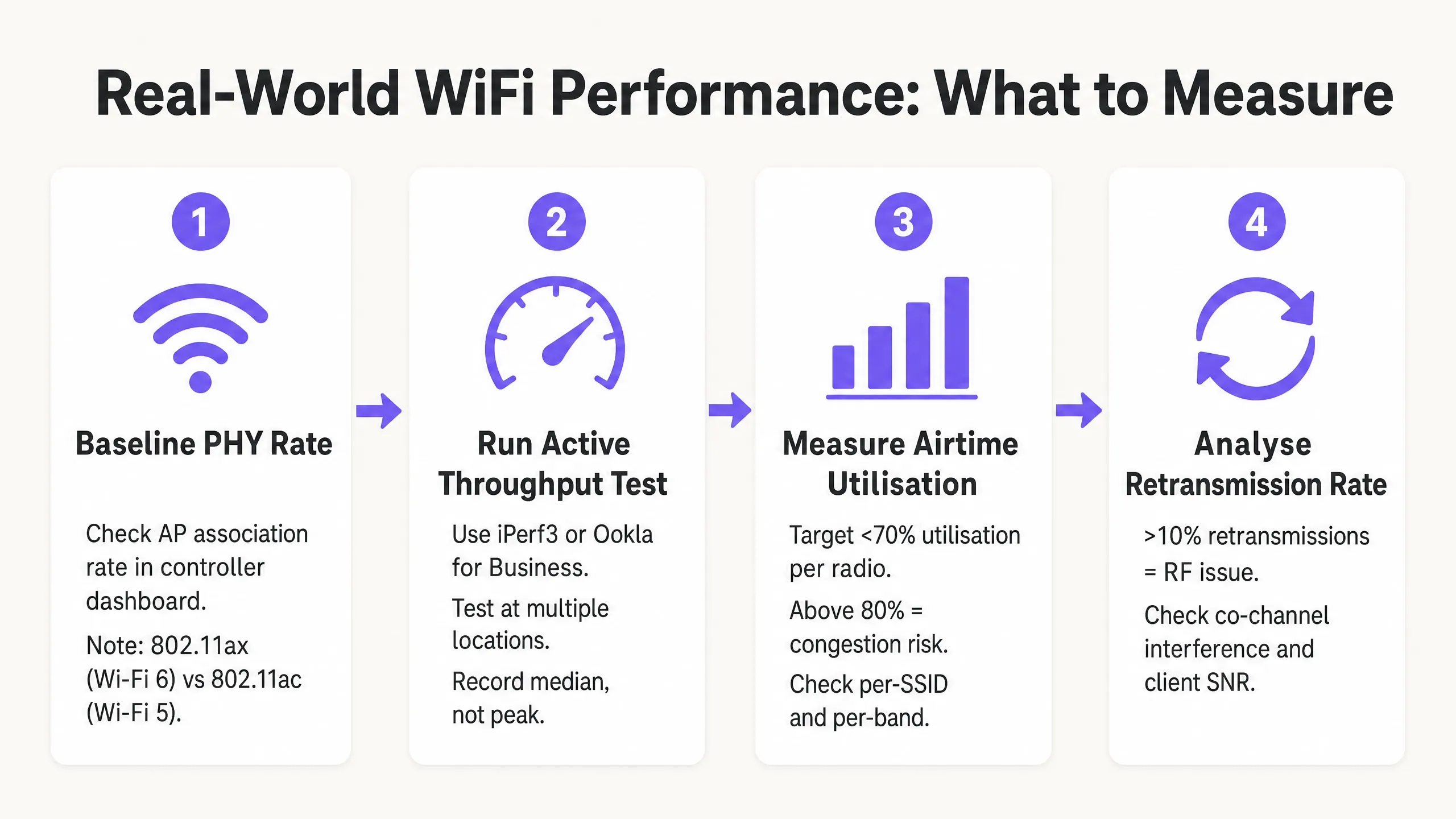
सिद्धांत से व्यवहार में संक्रमण के लिए कठोर माप पद्धति और व्यवस्थित ट्यूनिंग की आवश्यकता होती है। निम्नलिखित चरण सभी प्रमुख WLAN प्लेटफार्मों पर लागू होने वाले वेंडर-तटस्थ सर्वोत्तम प्रथाओं को दर्शाते।
चरण 1: सटीक बेसलाइन स्थापित करें
WLAN प्रदर्शन को मापने के लिए उपभोक्ता इंटरनेट स्पीड टेस्ट (जैसे fast.com या Speedtest.net) पर भरोसा न करें। ये परीक्षण WAN लेटेंसी, ISP रूटिंग वेरिएबल्स और सर्वर-साइड बाधाओं को पेश करते हैं जो पूरी तरह से आपके वायरलेस नेटवर्क से असंबंधित हैं। इसके बजाय, RF सेगमेंट को अलग करने के लिए AP प्रबंधन इंटरफ़ेस के समान VLAN पर एक स्थानीय iPerf3 सर्वर तैनात करें। कच्चे चैनल की क्षमता का आकलन करने के लिए UDP थ्रूपुट परीक्षण चलाएं, और एप्लिकेशन-स्तरीय प्रदर्शन का मूल्यांकन करने के लिए TCP थ्रूपुट परीक्षण चलाएं — TCP पैकेट हानि और लेटेंसी के प्रति अत्यधिक संवेदनशील है, जो इसे वास्तविक एप्लिकेशन व्यवहार के लिए एक सटीक प्रॉक्सी बनाता है।
चरण 2: एयरटाइम दक्षता के लिए डिजाइन करें
किसी भी WiFi परिनियोजन में एयरटाइम सबसे मूल्यवान संसाधन है। पूरे वेन्यू में थ्रूपुट को अधिकतम करने के लिए, तीन कॉन्फ़िगरेशन परिवर्तन सबसे बड़ा प्रभाव डालते हैं:
कम बेसिक दरों को अक्षम करें। 802.11b दरों (1, 2, 5.5, 11 Mbps) को अक्षम करें और 12 Mbps या 24 Mbps की न्यूनतम बेसिक दर अनिवार्य करें। यह क्लाइंट्स को प्रबंधन फ्रेम तेजी से ट्रांसमिट करने के लिए मजबूर करता, जिससे डेटा पेलोड के लिए एयरटाइम खाली हो जाता है। 1 Mbps पर भेजा गया एक एकल प्रबंधन फ्रेम 54 Mbps पर भेजे गए उसी फ्रेम की तुलना में 54 गुना अधिक एयरटाइम की खपत करता है।
एयरटाइम फेयरनेस (ATF) सक्षम करें। जहां वेंडर द्वारा समर्थित हो, क्लाइंट्स को समान पैकेट काउंट के बजाय समान ट्रांसमिशन समय आवंटित करने के लिए ATF सक्षम करें। यह धीमे पुराने क्लाइंट्स को तेज़, आधुनिक उपकरणों की कीमत पर चैनल पर एकाधिकार करने से रोकता है।
चैनल की चौड़ाई को अनुकूलित करें। उच्च-घनत्व वाले एंटरप्राइज परिनियोजन के लिए 2.4 GHz बैंड में डिफ़ॉल्ट रूप से 20 MHz चैनल (हमेशा चैनल 1, 6 और 11) और 5 GHz बैंड में 40 MHz रखें। 80 MHz चैनलों को केवल अलग-थलग, कम-घनत्व वाले वातावरण के लिए आरक्षित रखें।
चरण 3: आधुनिक प्रमाणीकरण और सुरक्षा लागू करें
सुरक्षा प्रोटोकॉल एन्क्रिप्शन ओवरहेड और रोमिंग लेटेंसी के माध्यम से थ्रूपुट को प्रभावित करते हैं। जहां क्लाइंट एस्टेट इसका समर्थन करता है वहां WPA3 लागू करें, या रोमिंग देरी को 50 ms से कम करने के लिए Fast BSS Transition (802.11r) के साथ WPA2-Enterprise (IEEE 802.1X) लागू करें। गेस्ट नेटवर्क के लिए, GDPR और PCI DSS का अनुपालन करने के लिए मजबूत नेटवर्क सेगमेंटेशन की आवश्यकता होती है — गेस्ट ट्रैफ़िक को समर्पित VLANs और फ़ायरवॉल नीतियों के माध्यम से कॉर्पोरेट और भुगतान बुनियादी ढांचे से अलग किया जाना चाहिए। आधुनिक ऑनबोर्डिंग समाधान जो अनुपालन बनाए रखते हुए प्रमाणीकरण घर्षण को कम करते हैं, उनकी चर्चा कैसे एक WiFi असिस्टेंट 2026 में पासवर्ड रहित एक्सेस सक्षम बनाता है में की गई है।
सर्वोत्तम अभ्यास और उद्योग मानक
निम्नलिखित सिद्धांत हेल्थकेयर , परिवहन और बड़े वेन्यू वातावरण में IEEE 802.11 वर्किंग ग्रुप की सिफारिशों और एंटरप्राइज WLAN परिनियोजन अनुभव की आम सहमति का प्रतिनिधित्व करते हैं।
कवरेज पर क्षमता। आधुनिक एंटरप्राइज वातावरण में, APs को केवल सिग्नल प्रदान करने के लिए नहीं, बल्कि क्लाइंट घनत्व को संभालने के लिए तैनात किया जाना चाहिए। यदि चैनल भीड़भाड़ वाला है, तो एक मजबूत सिग्नल (कवरेज) उच्च थ्रूपुट (क्षमता) की गारंटी नहीं देता है। ये दोनों पूरी तरह से अलग इंजीनियरिंग उद्देश्य हैं।
बैंड स्टीयरिंग। संकीर्ण 2.4 GHz स्पेक्ट्रम पर भीड़भाड़ को कम करने के लिए डुअल-बैंड और ट्राई-बैंड क्लाइंट्स को आक्रामक रूप से 5 GHz और 6 GHz बैंड पर निर्देशित करें। 2.4 GHz बैंड केवल तीन नॉन-ओवरलैपिंग चैनल (1, 6, 11) प्रदान करता है और गैर-WiFi उपकरणों से महत्वपूर्ण हस्तक्षेप के अधीन है।
न्यूनतम SNR थ्रेशोल्ड। न्यूनतम SNR थ्रेशोल्ड (आमतौर पर 20 dB) से नीचे क्लाइंट एसोसिएशन को अस्वीकार करने के लिए AP रेडियो को कॉन्फ़िगर करें। यह दूर के, कमजोर क्लाइंट्स को कम MCS दरों पर जुड़ने और ट्रांसमिट करने से रोकता है, जिससे अत्यधिक एयरटाइम की खपत होगी।
नियमित RF ऑडिट। कम से कम त्रैमासिक रूप से, और भौतिक वातावरण में किसी भी महत्वपूर्ण बदलाव (नए विभाजन, AV उपकरण, या किरायेदार परिवर्तन) के तुरंत बाद स्पेक्ट्रम विश्लेषण और सक्रिय थ्रूपुट परीक्षण आयोजित करें। RF वातावरण गतिशील है; परिनियोजन के समय काम करने वाली चैनल योजना छह महीने बाद उप-इष्टतम हो सकती है।
समस्या निवारण और जोखिम शमन
जब थ्रूपुट कम हो जाता है, तो IT टीमों को तुरंत हार्डवेयर अपग्रेड करने के बजाय व्यवस्थित रूप से RF वातावरण का निदान करना चाहिए। अधिकांश एंटरप्राइज WLAN प्रदर्शन समस्याएं कॉन्फ़िगरेशन और डिज़ाइन की समस्याएं हैं, न कि हार्डवेयर की सीमाएं।
उच्च रीट्रांसमिशन दरें। 10% से ऊपर की रीट्रांसमिशन दर आमतौर पर RF हस्तक्षेप, छिपी हुई नोड समस्याओं या खराब क्लाइंट SNR का संकेत देती है। गैर-WiFi हस्तक्षेप स्रोतों की पहचान करने के लिए स्पेक्ट्रम विश्लेषण टूल का उपयोग करें — माइक्रोवेव ओवन, AV उपकरण और पड़ोसी नेटवर्क हॉस्पिटैलिटी और रिटेल वातावरण में आम अपराधी हैं।
को-चैनल इंटरफेरेंस (CCI)। यदि एक ही चैनल पर कई APs एक-दूसरे को -85 dBm या उससे अधिक तेज़ सुन सकते हैं, तो वे एक ही कोलिजन डोमेन साझा करते हैं, जिससे उस चैनल पर सभी क्लाइंट्स के लिए थ्रूपुट काफी कम हो जाता है। AP ट्रांसमिट पावर को कम करके, चैनल की चौड़ाई को संकीर्ण करके, और यह सुनिश्चित करके कि डायनेमिक चैनल असाइनमेंट (DCA) एल्गोरिदम सही ढंग से काम कर रहे हैं, इसे कम करें।
स्टिकी क्लाइंट्स। जो क्लाइंट दूर के AP से नजदीकी AP पर रोम करने में विफल रहते हैं, वे कम SNR बनाए रखते हैं, जिससे AP को कम MCS दर का उपयोग करने के लिए मजबूर होना पड़ता है और अत्यधिक एयरटाइम की खपत होती है। एसोसिएशन के लिए न्यूनतम RSSI थ्रेशोल्ड, 802.11v BSS ट्रांज़िशन मैनेजमेंट और 802.11r फ़ास्ट रोमिंग के साथ इसे कम करें।
क्लाइंट ड्राइवर समस्याएं। अंतिम-उपयोगकर्ता उपकरणों पर पुराने वायरलेस ड्राइवर गलत MCS बातचीत, MIMO स्पेशल स्ट्रीम का उपयोग करने में विफलता, या आक्रामक पावर-सेविंग व्यवहार का कारण बन सकते हैं जो थ्रूपुट को बाधित करता है। एक क्लाइंट डिवाइस प्रबंधन नीति बनाए रखें जिसमें वायरलेस ड्राइवर संस्करण मानक शामिल हों।
ROI और व्यावसायिक प्रभाव
सैद्धांतिक लिंक स्पीड के बजाय थ्रूपुट के लिए WiFi को अनुकूलित करना सीधे तौर पर हर वर्टिकल में बॉटम लाइन को प्रभावित करता है। परिवहन हब और बड़े वेन्यू में, परिचालन दक्षता के लिए विश्वसनीय कनेक्टिविटी आवश्यक है — मोबाइल पॉइंट-ऑफ-सेल (mPOS) सिस्टम से लेकर डिजिटल साइनेज और एक्सेस कंट्रोल तक।
वेन्यू ऑपरेटरों के लिए, उच्च-थ्रूपुट नेटवर्क उन्नत स्थान-आधारित सेवाएं और एनालिटिक्स सक्षम करते हैं। लगातार, विश्वसनीय कनेक्टिविटी सुनिश्चित करना WiFi हॉटस्पॉट के लिए निर्बाध, सुरक्षित नेविगेशन के लिए Purple ने ऑफलाइन मैप्स मोड लॉन्च किया जैसी सुविधाओं के लिए एक पूर्वापेक्षा है, जो अतिथि अनुभव को बढ़ाती हैं और मापने योग्य जुड़ाव को बढ़ावा देती हैं। डिजिटल समावेशन और स्मार्ट सिटी नवाचार को बढ़ावा देने के लिए Purple ने इयान फॉक्स को VP ग्रोथ - पब्लिक सेक्टर नियुक्त किया में विस्तृत Purple का सार्वजनिक क्षेत्र का विस्तार, स्मार्ट सिटी सेवाओं की नींव के रूप में विश्वसनीय, उच्च-थ्रूपुट सार्वजनिक WiFi बुनियादी ढांचे के महत्व को और रेखांकित करता है।
थ्रूपुट-केंद्रित WLAN डिज़ाइन के लिए व्यावसायिक मामला सीधा है: एक नेटवर्क जो पीक आवर्स के दौरान प्रति क्लाइंट लगातार 200 Mbps प्रदान करता है, वह 85% एयरटाइम उपयोग और अप्रत्याशित वास्तविक दुनिया के प्रदर्शन के साथ 866 Mbps लिंक स्पीड देने वाले नेटवर्क की तुलना में अधिक मूल्यवान है। IT मेट्रिक्स — थ्रूपुट, एयरटाइम उपयोग, रीट्रांसमिशन दर — को व्यावसायिक परिणामों — अतिथि संतुष्टि स्कोर, mPOS लेनदेन विश्वसनीयता, परिचालन अपटाइम — के साथ संरेखित करके, IT लीडर बुनियादी ढांचे के निवेश को सही ठहरा सकते हैं और स्पष्ट, मापने योग्य ROI प्रदर्शित कर सकते हैं।
Key Definitions
Link Speed (PHY Rate)
The maximum theoretical physical layer data rate negotiated between a client and an AP, measured in Mbps. Determined by MCS index, spatial streams, and channel width.
Frequently cited in vendor marketing and procurement documents. IT teams must understand this is a gross rate that includes massive protocol overhead and is never achievable as application throughput.
Throughput
The actual rate of successful payload data delivery over a communication channel to the application layer, measured in Mbps.
The primary KPI for any WLAN performance assessment. The only metric that accurately reflects end-user experience and application performance.
Bandwidth (RF Channel Width)
The width of the frequency spectrum allocated for a transmission channel, typically 20, 40, 80, or 160 MHz in the 5 GHz band.
Determines the potential capacity of the channel. Wider bandwidths increase peak link speed but reduce the number of non-overlapping channels and increase susceptibility to interference in dense deployments.
Co-Channel Interference (CCI)
Performance degradation caused when multiple APs operate on the same frequency channel and can detect each other's transmissions, forcing them to share airtime via the CSMA/CA contention mechanism.
The primary cause of poor throughput in dense enterprise deployments. Mitigated by proper channel planning, reduced transmit power, and narrower channel widths.
Airtime Utilisation
The percentage of time a specific RF channel is occupied with transmissions (data, management, or control frames).
A critical operational metric. Sustained utilisation above 70–80% indicates severe congestion and impending throughput collapse. Should be monitored per-radio and per-SSID.
Half-Duplex
A communication mode where data can be transmitted in both directions, but only one direction at a time on a shared medium.
The fundamental characteristic of WiFi that limits throughput to significantly below the theoretical link speed. Unlike wired Ethernet (full-duplex), WiFi requires all devices to take turns transmitting.
Spatial Streams (MIMO)
Multiple independent data signals transmitted simultaneously using Multiple Input Multiple Output (MIMO) antenna technology, increasing throughput without requiring wider bandwidth.
A key differentiator between 802.11ac (up to 8 spatial streams) and 802.11ax (Wi-Fi 6). Effective only when both the AP and client device support multiple antennas.
Basic Rates
The mandatory data rates that all clients must support to associate with a BSS. Management and control frames are transmitted at the lowest enabled basic rate.
Disabling low basic rates (1, 2, 5.5, 11 Mbps) is a standard and highly effective IT configuration practice. A frame sent at 1 Mbps consumes 54 times more airtime than the same frame at 54 Mbps.
MCS (Modulation and Coding Scheme)
An index value that defines the combination of modulation technique (e.g., 256-QAM, 1024-QAM) and forward error correction coding rate used for a given transmission.
Higher MCS indices deliver higher throughput but require a stronger signal-to-noise ratio. The AP and client negotiate the highest feasible MCS based on current RF conditions.
Worked Examples
A 400-room hotel is experiencing guest complaints about slow WiFi speeds during the evening peak (7 PM – 10 PM). The IT manager notes that the APs are reporting link speeds of 866 Mbps, but guests are struggling to stream video. The network uses 80 MHz channels on the 5 GHz band with APs deployed in corridors at maximum transmit power.
- Conduct an airtime utilisation assessment during peak hours using the WLAN controller's built-in analytics or a dedicated tool such as Ekahau Sidekick. Expect to find utilisation above 80% on the primary 5 GHz channels, confirming Co-Channel Interference (CCI). 2. Reconfigure the WLAN controller to reduce channel widths on the 5 GHz band from 80 MHz to 40 MHz. This doubles the number of available non-overlapping channels from 6 to 12 in the UNII-1/UNII-3 bands, significantly reducing CCI. 3. Reduce AP transmit power to approximately 11–14 dBm to shrink cell sizes and reduce the number of APs that can hear each other on the same channel. 4. Enable dynamic channel assignment (DCA) to allow the controller to optimise channel allocation automatically. 5. Implement per-client bandwidth throttling (e.g., 15 Mbps downstream per device) to prevent individual users from monopolising the internet uplink during peak hours.
A large retail chain is deploying mobile Point-of-Sale (mPOS) tablets across 50 stores. The tablets require reliable, low-latency connections for payment processing, but are frequently dropping sessions when staff move between aisles. The WLAN uses WPA2-Personal with default basic rates enabled.
- Implement IEEE 802.11r (Fast BSS Transition) on the corporate mPOS SSID to reduce roaming authentication delays from 300–500 ms to under 50 ms. This is critical for session-sensitive payment applications. 2. Adjust the AP minimum mandatory basic rate to 12 Mbps. This reduces the effective cell size, encouraging tablets to roam to closer APs sooner rather than maintaining a weak connection to a distant AP (sticky client behaviour). 3. Migrate the mPOS SSID from WPA2-Personal to WPA2-Enterprise (802.1X) with certificate-based authentication to meet PCI DSS requirements for cardholder data environments. 4. Apply WMM (Wi-Fi Multimedia) QoS tags to the mPOS SSID, prioritising traffic in the Voice or Video queue to protect throughput during periods of high guest network usage. 5. Implement 802.11k (Neighbour Reports) and 802.11v (BSS Transition Management) to assist tablets in identifying and roaming to optimal APs proactively.
Practice Questions
Q1. You are designing the WLAN for a high-density university lecture theatre with 300 seats. Your goal is to maximise aggregate throughput for all users simultaneously. The venue has 8 APs deployed in the ceiling. Should you configure the 5 GHz radios to use 20 MHz, 40 MHz, or 80 MHz channel widths?
Hint: Consider the number of non-overlapping channels available in the 5 GHz UNII-1 and UNII-3 bands, and the impact of Co-Channel Interference in a single open room with multiple APs.
View model answer
Use 20 MHz channels. In a high-density, single-room environment with 8 APs, you need each AP to operate on a distinct, non-overlapping channel to avoid CCI. The 5 GHz band offers approximately 24 non-overlapping 20 MHz channels (in regions with full UNII band access), but only 6 non-overlapping 40 MHz channels and 3 non-overlapping 80 MHz channels. With 8 APs using 80 MHz channels, at least 5 APs would be sharing channels, creating severe CCI. By using 20 MHz channels, you can assign unique channels to all 8 APs, allowing them to transmit simultaneously without contention. The individual link speed per client will be lower, but the aggregate throughput across all 300 users will be dramatically higher.
Q2. A client complains that their new 802.11ax (Wi-Fi 6) laptop only achieves 480 Mbps on a local iPerf3 test, despite Windows reporting a link speed of 1.2 Gbps. The client believes the AP is faulty. How do you assess and explain this situation?
Hint: Apply the Rule of Half and consider the relationship between PHY rate and TCP throughput in a half-duplex medium.
View model answer
The AP is almost certainly functioning correctly. The 1.2 Gbps is the negotiated Link Speed (PHY rate) — the gross theoretical radio rate. Because WiFi is half-duplex, and because the 802.11 protocol requires significant overhead (management frames, ACKs, inter-frame spacing), actual TCP throughput is typically 40–60% of the link speed. 480 Mbps from a 1.2 Gbps link represents a 40% efficiency ratio, which is within the expected range and indicates the network is performing well. To confirm, check the retransmission rate (should be below 5%) and airtime utilisation (should be below 50% for a single-client test). If both are healthy, the result is excellent and the AP should not be replaced.
Q3. During a site survey in a busy retail warehouse, you notice the airtime utilisation on channel 6 (2.4 GHz) is consistently at 88%, but there are only 6 active clients connected to the AP. The AP is a modern 802.11ax device. What are the two most likely causes, and what is the remediation for each?
Hint: Think about how legacy data rates affect airtime consumption, and consider sources of non-WiFi interference common in warehouse environments.
View model answer
Cause 1: Legacy basic rates are enabled. If the AP is transmitting management frames (beacons, probe responses) at 1 Mbps, each frame takes 54 times longer than at 54 Mbps, consuming enormous amounts of airtime even with few clients. Remediation: Disable 802.11b rates and set the minimum basic rate to 12 Mbps or 24 Mbps. Cause 2: Non-WiFi interference in the 2.4 GHz band. Warehouses commonly contain microwave ovens, Bluetooth devices, and older industrial wireless equipment that generate broadband interference in the 2.4 GHz band, artificially inflating airtime utilisation figures. Remediation: Conduct a spectrum analysis using a tool such as Ekahau Sidekick or a dedicated spectrum analyser to identify the interference source, and where possible migrate clients to the 5 GHz band.
Continue reading in this series
Understanding RSSI and Signal Strength for Optimal Channel Planning
This guide provides a comprehensive technical deep-dive into RSSI, Signal-to-Noise Ratio (SNR), and RF propagation principles for optimal channel planning. It equips IT managers, network architects, and venue operations directors with actionable strategies to mitigate Co-Channel and Adjacent Channel Interference, optimise AP placement, and leverage analytics for measurable business impact across hospitality, retail, and public-sector environments.
20MHz vs 40MHz vs 80MHz: Which Channel Width Should You Use?
This guide provides a definitive, vendor-neutral technical reference for IT managers, network architects, and venue operations directors on selecting the correct WiFi channel width — 20MHz, 40MHz, or 80MHz — across enterprise deployments in hospitality, retail, events, and public-sector environments. It covers the underlying IEEE 802.11 mechanics, real-world capacity trade-offs, and step-by-step deployment guidance to help teams make the right call this quarter. Understanding channel width selection is one of the highest-leverage decisions in any wireless LAN design, directly impacting throughput, interference, client density support, and the reliability of guest-facing services.