Comprendiendo el significado de la velocidad WiFi: Throughput vs Bandwidth
Esta guía de referencia técnica autorizada desmitifica las métricas de velocidad WiFi para líderes de TI empresariales, distinguiendo claramente entre velocidad de enlace, ancho de banda y throughput. Proporciona metodologías accionables para medir el rendimiento en el mundo real, mitigar la congestión de RF y optimizar la infraestructura WLAN en despliegues de alta densidad. Los gerentes de TI, arquitectos de red y directores de operaciones de recintos saldrán con marcos concretos para alinear las inversiones en infraestructura con resultados de negocio medibles.
Escuchar esta guía
Ver transcripción del podcast

Resumen Ejecutivo
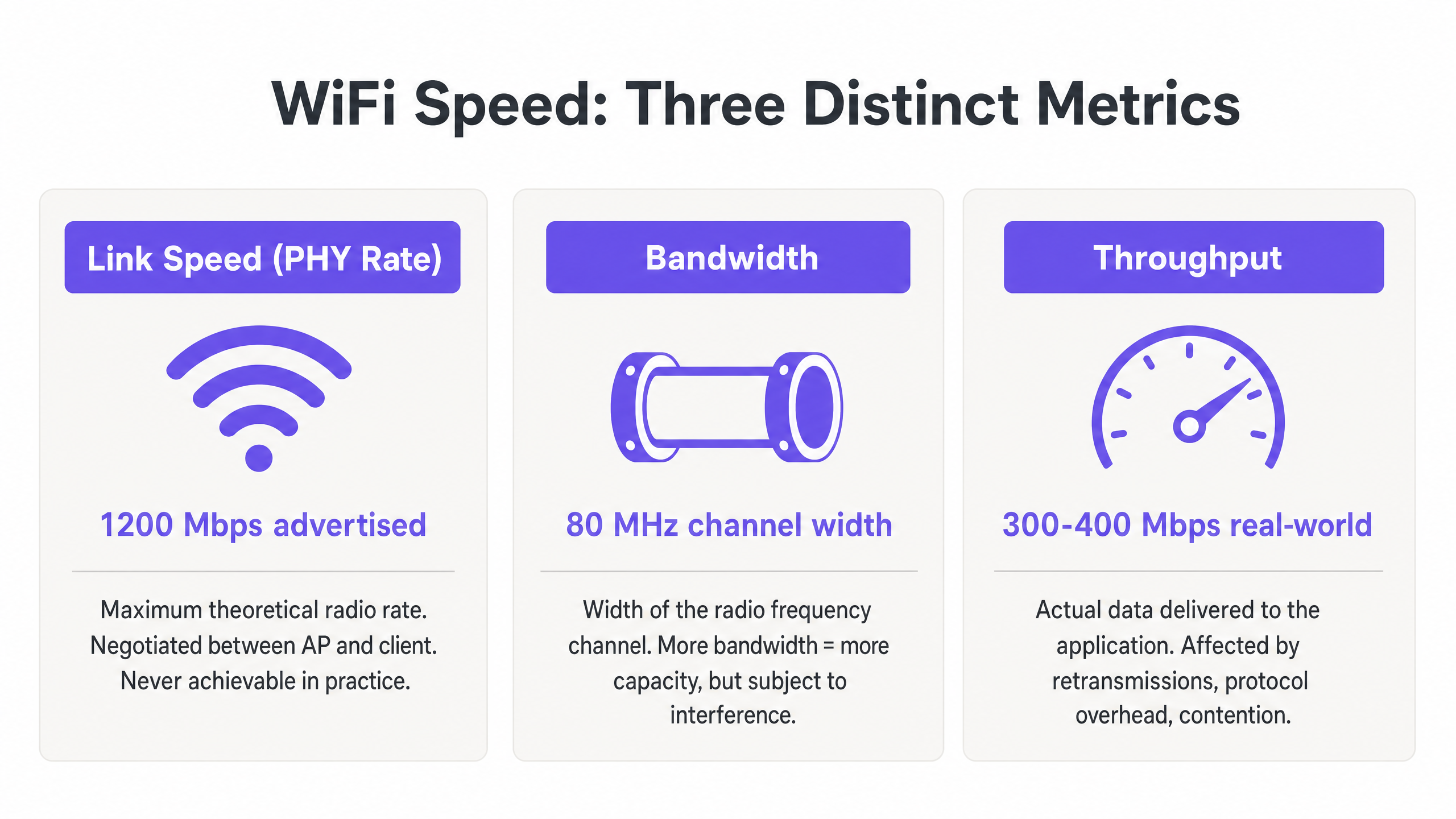
Para los gerentes de TI y arquitectos de red que implementan WLANs empresariales, la discrepancia entre las velocidades WiFi anunciadas y la experiencia real del usuario es un desafío operativo persistente. La causa principal es casi siempre una mala interpretación de tres métricas distintas: velocidad de enlace (tasa PHY), ancho de banda y throughput. Mientras que los proveedores comercializan velocidades de enlace teóricas máximas —por ejemplo, 1200 Mbps en 802.11ax—, el throughput real entregado a una aplicación es típicamente del 40-60% de esa cifra debido a la sobrecarga del protocolo, la operación de radio semidúplex y la contención ambiental.
Esta guía de referencia técnica proporciona un marco definitivo para comprender el significado de la velocidad WiFi en entornos empresariales. Equipa a los equipos de TI de hoteles, cadenas minoristas y grandes recintos con el conocimiento para medir con precisión el rendimiento en el mundo real, diseñar para la capacidad en lugar de la cobertura, y alinear las inversiones en infraestructura con resultados de negocio medibles. Al cambiar el enfoque de los máximos teóricos a un throughput sostenido y una asignación óptima de ancho de banda, los operadores de recintos pueden ofrecer la conectividad fiable que exigen las plataformas modernas de Guest WiFi y WiFi Analytics .
Análisis Técnico Detallado: Decodificando las Métricas de Velocidad WiFi
Para diseñar una WLAN robusta, los profesionales de TI deben distinguir entre las capacidades teóricas del medio RF y la entrega práctica de cargas de datos. Las tres métricas —velocidad de enlace, ancho de banda y throughput— se confunden con frecuencia en el marketing de los proveedores, las discusiones de adquisición e incluso en los informes internos de TI. Entender esto correctamente es fundamental para cualquier otra decisión de optimización.
Velocidad de Enlace (Tasa PHY): El Techo Teórico
La velocidad de enlace, o tasa de la Capa Física (PHY), representa la tasa máxima teórica de transferencia de datos entre un Access Point (AP) y un dispositivo cliente a nivel de radio. Esta tasa se negocia dinámicamente en función del esquema de modulación y codificación (MCS), el número de flujos espaciales y la relación señal/ruido (SNR) en el momento de la asociación.
Fundamentalmente, la velocidad de enlace nunca es alcanzable en la práctica. Representa la tasa de bits bruta, incluyendo todos los tramas de gestión 802.11, tramas de control (RTS/CTS y ACKs) y el espaciado entre tramas (AIFS/DIFS). En despliegues empresariales en entornos de Retail u Hospitality , un cliente que informa una velocidad de enlace de 866 Mbps en una red 802.11ac es realmente capaz de aproximadamente 400–500 Mbps de transferencia de datos real bajo condiciones ideales y aisladas —y mucho menos en un entorno compartido y multi-cliente.
Ancho de Banda: La Capacidad del Canal RF
El ancho de banda se refiere al ancho del canal de radiofrecuencia asignado para la transmisión, típicamente medido en Megahertz (MHz). En las bandas de 5 GHz y 6 GHz, los canales pueden tener 20, 40, 80 o 160 MHz de ancho. Los canales más anchos ofrecen velocidades de enlace potenciales más altas —duplicar el ancho del canal duplica aproximadamente la tasa de datos potencial—, pero también aumentan el nivel de ruido en 3 dB por cada duplicación y reducen significativamente el número de canales no superpuestos disponibles.
En entornos de alta densidad como estadios, centros de conferencias o pasillos de hoteles, el despliegue de canales de 80 MHz a menudo conduce a una interferencia cocanal (CCI) catastrófica. La mejor práctica empresarial, por lo tanto, dicta el uso de canales de 20 MHz o 40 MHz para maximizar la reutilización espectral y la capacidad general del sistema, en lugar de buscar velocidades individuales máximas. Esta es una filosofía de diseño que prioriza el throughput agregado entre todos los usuarios sobre el máximo teórico para cualquier usuario individual.
Throughput: La Medida del Mundo Real
El throughput es la carga de datos real entregada a la capa de aplicación (Capa 7), medida en Megabits por segundo (Mbps). Esta es la única métrica que importa al usuario final, y es la única métrica que debe impulsar las decisiones de diseño de red.
El throughput está fundamentalmente limitado por la naturaleza semidúplex de WiFi —solo un dispositivo puede transmitir en un canal dado a la vez. Cuando múltiples dispositivos compiten por el tiempo de aire, el throughput disminuye proporcionalmente. Además, los clientes heredados que transmiten a tasas de datos más bajas consumen un tiempo de aire desproporcionado, penalizando a los clientes más rápidos que comparten el mismo canal. Comprender el verdadero coste del consumo de tiempo de aire es crítico al evaluar el impacto de la recopilación de datos en segundo plano en su WLAN, como se explora en profundidad en El coste oculto de los datos de telemetría en las WLAN corporativas .
La tabla siguiente resume la relación práctica entre estas tres métricas:
| Métrica | Definición | Valor Típico (802.11ax) | Qué Deben Hacer los Equipos de TI |
|---|---|---|---|
| Velocidad de Enlace (Tasa PHY) | Tasa de radio teórica bruta | Hasta 9.6 Gbps | Usar solo como indicador de referencia; nunca como objetivo de rendimiento |
| Ancho de Banda (Ancho de Canal) | Ancho de canal RF en MHz | 20, 40, 80 o 160 MHz | Por defecto 40 MHz en entornos empresariales; 20 MHz en alta densidad |
| Throughput | Tasa de datos real de la capa de aplicación | 300–500 Mbps por cliente (ideal) | Este es el KPI principal para todas las evaluaciones de rendimiento de WLAN |
Guía de Implementación: Medición y Optimización del Rendimiento
La transición de la teoría a la práctica requiere una metodología de medición rigurosa y una sintonización sistemática. Los siguientes pasos reflejan las mejores prácticas neutrales al proveedor aplicables a lo largoss all major WLAN platforms.
Paso 1: Establecer Líneas Base Precisas
No confíe en las pruebas de velocidad de internet para consumidores (como fast.com o Speedtest.net) para medir el rendimiento de la WLAN. Estas pruebas introducen latencia WAN, variables de enrutamiento del ISP y cuellos de botella del lado del servidor que no están relacionados en absoluto con su red inalámbrica. En su lugar, implemente un servidor iPerf3 local en la misma VLAN que la interfaz de gestión del AP para aislar el segmento RF. Ejecute pruebas de rendimiento UDP para evaluar la capacidad bruta del canal y pruebas de rendimiento TCP para evaluar el rendimiento a nivel de aplicación — TCP es altamente sensible a la pérdida de paquetes y la latencia, lo que lo convierte en un proxy preciso para el comportamiento real de la aplicación.
Paso 2: Diseñar para la Eficiencia del Tiempo de Aire
El tiempo de aire es el recurso más valioso en cualquier implementación WiFi. Para maximizar el rendimiento en todo el recinto, tres cambios de configuración ofrecen el mayor impacto:
Deshabilitar Tasas Básicas Bajas. Deshabilite las tasas 802.11b (1, 2, 5.5, 11 Mbps) y exija una tasa básica mínima de 12 Mbps o 24 Mbps. Esto obliga a los clientes a transmitir tramas de gestión más rápido, liberando tiempo de aire para las cargas de datos. Una sola trama de gestión enviada a 1 Mbps consume 54 veces más tiempo de aire que la misma trama enviada a 54 Mbps.
Habilitar Airtime Fairness (ATF). Cuando sea compatible con el proveedor, habilite ATF para asignar el mismo tiempo de transmisión a los clientes, en lugar de la misma cantidad de paquetes. Esto evita que los clientes lentos y heredados monopolicen el canal a expensas de dispositivos modernos más rápidos.
Optimizar Anchos de Canal. Por defecto, use canales de 20 MHz en la banda de 2.4 GHz (siempre canales 1, 6 y 11) y 40 MHz en la banda de 5 GHz para implementaciones empresariales de alta densidad. Reserve los canales de 80 MHz solo para entornos aislados y de baja densidad.

Paso 3: Implementar Autenticación y Seguridad Modernas
Los protocolos de seguridad impactan el rendimiento a través de la sobrecarga de cifrado y la latencia de roaming. Implemente WPA3 donde el parque de clientes lo admita, o WPA2-Enterprise (IEEE 802.1X) con Fast BSS Transition (802.11r) para minimizar los retrasos de roaming por debajo de 50 ms. Para las redes de invitados, el cumplimiento de GDPR y PCI DSS requiere una segmentación de red robusta — el tráfico de invitados debe aislarse de la infraestructura corporativa y de pagos mediante VLANs dedicadas y políticas de firewall. Las soluciones modernas de incorporación que reducen la fricción de autenticación mientras mantienen el cumplimiento se discuten en Cómo un wi fi assistant habilita el acceso sin contraseña en 2026 .
Mejores Prácticas y Estándares de la Industria
Los siguientes principios representan el consenso de las recomendaciones del grupo de trabajo IEEE 802.11 y la experiencia en la implementación de WLAN empresariales en Sanidad , Transporte y entornos de grandes recintos.
Capacidad sobre Cobertura. En entornos empresariales modernos, los APs deben implementarse para gestionar la densidad de clientes, no solo para proporcionar una señal. Una señal fuerte (cobertura) no garantiza un alto rendimiento (capacidad) si el canal está congestionado. Los dos son objetivos de ingeniería completamente diferentes.
Band Steering. Dirija agresivamente a los clientes de doble banda y triple banda a las bandas de 5 GHz y 6 GHz para aliviar la congestión en el estrecho espectro de 2.4 GHz. La banda de 2.4 GHz ofrece solo tres canales no superpuestos (1, 6, 11) y está sujeta a una interferencia significativa de dispositivos que no son WiFi.
Umbrales Mínimos de SNR. Configure las radios de los AP para rechazar asociaciones de clientes por debajo de un umbral SNR mínimo (típicamente 20 dB). Esto evita que los clientes distantes y débiles se asocien y transmitan a bajas tasas MCS, lo que consumiría un tiempo de aire excesivo.
Auditorías RF Regulares. Realice análisis de espectro y pruebas de rendimiento activas al menos trimestralmente, e inmediatamente después de cualquier cambio significativo en el entorno físico (nuevas particiones, equipos AV o cambios de inquilinos). El entorno RF es dinámico; un plan de canales que funcionó en el momento de la implementación puede ser subóptimo seis meses después.
Resolución de Problemas y Mitigación de Riesgos
Cuando el rendimiento se degrada, los equipos de TI deben diagnosticar el entorno RF sistemáticamente en lugar de recurrir inmediatamente a actualizaciones de hardware. La mayoría de los problemas de rendimiento de WLAN empresariales son problemas de configuración y diseño, no limitaciones de hardware.
Altas Tasas de Retransmisión. Una tasa de retransmisión superior al 10% típicamente indica interferencia RF, problemas de nodo oculto o un SNR deficiente del cliente. Utilice herramientas de análisis de espectro para identificar fuentes de interferencia no WiFi — hornos microondas, equipos AV y redes vecinas son culpables comunes en entornos de hostelería y minoristas.
Interferencia Co-Canal (CCI). Si múltiples APs en el mismo canal pueden escucharse entre sí a -85 dBm o más fuerte, comparten el mismo dominio de colisión, reduciendo drásticamente el rendimiento para todos los clientes en ese canal. Mitigue esto reduciendo la potencia de transmisión del AP, estrechando los anchos de canal y asegurándose de que los algoritmos de asignación dinámica de canales (DCA) funcionen correctamente.
Clientes Pegajosos. Los clientes que no logran pasar de un AP distante a uno más cercano mantienen un SNR bajo, lo que obliga al AP a usar una tasa MCS baja y a consumir un tiempo de aire excesivo. Mitigue con umbrales RSSI mínimos para la asociación, 802.11v BSS Transition Management y 802.11r Fast Roaming.
Problemas de Controladores de Cliente. Los controladores inalámbricos desactualizados en los dispositivos de usuario final pueden causar una negociación MCS incorrecta, la imposibilidad de usar flujos espaciales MIMO o un comportamiento agresivo de ahorro de energía que interrumpe el rendimiento. Mantenga una política de gestión de dispositivos de cliente que incluya estándares de versión de controladores inalámbricos.
ROI e Impacto Empresarial
Optimizar WiFi para el rendimiento en lugar de la velocidad de enlace teórica impacta directamente en los resultados finales en todos los sectores. En los centros de Transporte y grandes recintos, la conectividad fiable es esencial para la eficiencia operativa — desde sistemas de punto de venta móviles (mPOS) a la señalización digital y el control de acceso.
Para los operadores de recintos, las redes de alto rendimiento permiten servicios y análisis avanzados basados en la ubicación. Garantizar una conectividad consistente y fiable es un requisito previo para funciones como las introducidas en Purple Launches Offline Maps Mode for Seamless, Secure Navigation to WiFi Hotspots , que mejoran la experiencia del huésped e impulsan un compromiso medible. La expansión de Purple en el sector público, detallada en Purple Appoints Iain Fox as VP Growth – Public Sector to Drive Digital Inclusion and Smart City Innovation , subraya aún más la importancia de una infraestructura WiFi pública fiable y de alto rendimiento como base para los servicios de ciudades inteligentes.
El caso de negocio para un diseño de WLAN centrado en el rendimiento es sencillo: una red que ofrece 200 Mbps consistentes por cliente durante las horas pico es más valiosa que una que ofrece una velocidad de enlace de 866 Mbps con un 85% de utilización del tiempo de aire y un rendimiento impredecible en el mundo real. Al alinear las métricas de TI — rendimiento, utilización del tiempo de aire, tasa de retransmisión — con los resultados de negocio — puntuaciones de satisfacción del huésped, fiabilidad de las transacciones mPOS, tiempo de actividad operativa — los líderes de TI pueden justificar las inversiones en infraestructura y demostrar un ROI claro y medible.
Definiciones clave
Link Speed (PHY Rate)
The maximum theoretical physical layer data rate negotiated between a client and an AP, measured in Mbps. Determined by MCS index, spatial streams, and channel width.
Frequently cited in vendor marketing and procurement documents. IT teams must understand this is a gross rate that includes massive protocol overhead and is never achievable as application throughput.
Throughput
The actual rate of successful payload data delivery over a communication channel to the application layer, measured in Mbps.
The primary KPI for any WLAN performance assessment. The only metric that accurately reflects end-user experience and application performance.
Bandwidth (RF Channel Width)
The width of the frequency spectrum allocated for a transmission channel, typically 20, 40, 80, or 160 MHz in the 5 GHz band.
Determines the potential capacity of the channel. Wider bandwidths increase peak link speed but reduce the number of non-overlapping channels and increase susceptibility to interference in dense deployments.
Co-Channel Interference (CCI)
Performance degradation caused when multiple APs operate on the same frequency channel and can detect each other's transmissions, forcing them to share airtime via the CSMA/CA contention mechanism.
The primary cause of poor throughput in dense enterprise deployments. Mitigated by proper channel planning, reduced transmit power, and narrower channel widths.
Airtime Utilisation
The percentage of time a specific RF channel is occupied with transmissions (data, management, or control frames).
A critical operational metric. Sustained utilisation above 70–80% indicates severe congestion and impending throughput collapse. Should be monitored per-radio and per-SSID.
Half-Duplex
A communication mode where data can be transmitted in both directions, but only one direction at a time on a shared medium.
The fundamental characteristic of WiFi that limits throughput to significantly below the theoretical link speed. Unlike wired Ethernet (full-duplex), WiFi requires all devices to take turns transmitting.
Spatial Streams (MIMO)
Multiple independent data signals transmitted simultaneously using Multiple Input Multiple Output (MIMO) antenna technology, increasing throughput without requiring wider bandwidth.
A key differentiator between 802.11ac (up to 8 spatial streams) and 802.11ax (Wi-Fi 6). Effective only when both the AP and client device support multiple antennas.
Basic Rates
The mandatory data rates that all clients must support to associate with a BSS. Management and control frames are transmitted at the lowest enabled basic rate.
Disabling low basic rates (1, 2, 5.5, 11 Mbps) is a standard and highly effective IT configuration practice. A frame sent at 1 Mbps consumes 54 times more airtime than the same frame at 54 Mbps.
MCS (Modulation and Coding Scheme)
An index value that defines the combination of modulation technique (e.g., 256-QAM, 1024-QAM) and forward error correction coding rate used for a given transmission.
Higher MCS indices deliver higher throughput but require a stronger signal-to-noise ratio. The AP and client negotiate the highest feasible MCS based on current RF conditions.
Ejemplos prácticos
A 400-room hotel is experiencing guest complaints about slow WiFi speeds during the evening peak (7 PM – 10 PM). The IT manager notes that the APs are reporting link speeds of 866 Mbps, but guests are struggling to stream video. The network uses 80 MHz channels on the 5 GHz band with APs deployed in corridors at maximum transmit power.
- Conduct an airtime utilisation assessment during peak hours using the WLAN controller's built-in analytics or a dedicated tool such as Ekahau Sidekick. Expect to find utilisation above 80% on the primary 5 GHz channels, confirming Co-Channel Interference (CCI). 2. Reconfigure the WLAN controller to reduce channel widths on the 5 GHz band from 80 MHz to 40 MHz. This doubles the number of available non-overlapping channels from 6 to 12 in the UNII-1/UNII-3 bands, significantly reducing CCI. 3. Reduce AP transmit power to approximately 11–14 dBm to shrink cell sizes and reduce the number of APs that can hear each other on the same channel. 4. Enable dynamic channel assignment (DCA) to allow the controller to optimise channel allocation automatically. 5. Implement per-client bandwidth throttling (e.g., 15 Mbps downstream per device) to prevent individual users from monopolising the internet uplink during peak hours.
A large retail chain is deploying mobile Point-of-Sale (mPOS) tablets across 50 stores. The tablets require reliable, low-latency connections for payment processing, but are frequently dropping sessions when staff move between aisles. The WLAN uses WPA2-Personal with default basic rates enabled.
- Implement IEEE 802.11r (Fast BSS Transition) on the corporate mPOS SSID to reduce roaming authentication delays from 300–500 ms to under 50 ms. This is critical for session-sensitive payment applications. 2. Adjust the AP minimum mandatory basic rate to 12 Mbps. This reduces the effective cell size, encouraging tablets to roam to closer APs sooner rather than maintaining a weak connection to a distant AP (sticky client behaviour). 3. Migrate the mPOS SSID from WPA2-Personal to WPA2-Enterprise (802.1X) with certificate-based authentication to meet PCI DSS requirements for cardholder data environments. 4. Apply WMM (Wi-Fi Multimedia) QoS tags to the mPOS SSID, prioritising traffic in the Voice or Video queue to protect throughput during periods of high guest network usage. 5. Implement 802.11k (Neighbour Reports) and 802.11v (BSS Transition Management) to assist tablets in identifying and roaming to optimal APs proactively.
Preguntas de práctica
Q1. You are designing the WLAN for a high-density university lecture theatre with 300 seats. Your goal is to maximise aggregate throughput for all users simultaneously. The venue has 8 APs deployed in the ceiling. Should you configure the 5 GHz radios to use 20 MHz, 40 MHz, or 80 MHz channel widths?
Sugerencia: Consider the number of non-overlapping channels available in the 5 GHz UNII-1 and UNII-3 bands, and the impact of Co-Channel Interference in a single open room with multiple APs.
Ver respuesta modelo
Use 20 MHz channels. In a high-density, single-room environment with 8 APs, you need each AP to operate on a distinct, non-overlapping channel to avoid CCI. The 5 GHz band offers approximately 24 non-overlapping 20 MHz channels (in regions with full UNII band access), but only 6 non-overlapping 40 MHz channels and 3 non-overlapping 80 MHz channels. With 8 APs using 80 MHz channels, at least 5 APs would be sharing channels, creating severe CCI. By using 20 MHz channels, you can assign unique channels to all 8 APs, allowing them to transmit simultaneously without contention. The individual link speed per client will be lower, but the aggregate throughput across all 300 users will be dramatically higher.
Q2. A client complains that their new 802.11ax (Wi-Fi 6) laptop only achieves 480 Mbps on a local iPerf3 test, despite Windows reporting a link speed of 1.2 Gbps. The client believes the AP is faulty. How do you assess and explain this situation?
Sugerencia: Apply the Rule of Half and consider the relationship between PHY rate and TCP throughput in a half-duplex medium.
Ver respuesta modelo
The AP is almost certainly functioning correctly. The 1.2 Gbps is the negotiated Link Speed (PHY rate) — the gross theoretical radio rate. Because WiFi is half-duplex, and because the 802.11 protocol requires significant overhead (management frames, ACKs, inter-frame spacing), actual TCP throughput is typically 40–60% of the link speed. 480 Mbps from a 1.2 Gbps link represents a 40% efficiency ratio, which is within the expected range and indicates the network is performing well. To confirm, check the retransmission rate (should be below 5%) and airtime utilisation (should be below 50% for a single-client test). If both are healthy, the result is excellent and the AP should not be replaced.
Q3. During a site survey in a busy retail warehouse, you notice the airtime utilisation on channel 6 (2.4 GHz) is consistently at 88%, but there are only 6 active clients connected to the AP. The AP is a modern 802.11ax device. What are the two most likely causes, and what is the remediation for each?
Sugerencia: Think about how legacy data rates affect airtime consumption, and consider sources of non-WiFi interference common in warehouse environments.
Ver respuesta modelo
Cause 1: Legacy basic rates are enabled. If the AP is transmitting management frames (beacons, probe responses) at 1 Mbps, each frame takes 54 times longer than at 54 Mbps, consuming enormous amounts of airtime even with few clients. Remediation: Disable 802.11b rates and set the minimum basic rate to 12 Mbps or 24 Mbps. Cause 2: Non-WiFi interference in the 2.4 GHz band. Warehouses commonly contain microwave ovens, Bluetooth devices, and older industrial wireless equipment that generate broadband interference in the 2.4 GHz band, artificially inflating airtime utilisation figures. Remediation: Conduct a spectrum analysis using a tool such as Ekahau Sidekick or a dedicated spectrum analyser to identify the interference source, and where possible migrate clients to the 5 GHz band.