Comprendere il significato della velocità WiFi: Throughput vs Larghezza di banda
Questa guida tecnica di riferimento autorevole demistifica le metriche di velocità WiFi per i leader IT aziendali, distinguendo chiaramente tra link speed, bandwidth e throughput. Fornisce metodologie attuabili per misurare le prestazioni nel mondo reale, mitigare la congestione RF e ottimizzare l'infrastruttura WLAN in implementazioni in luoghi ad alta densità. I manager IT, gli architetti di rete e i direttori delle operazioni delle sedi avranno a disposizione framework concreti per allineare gli investimenti infrastrutturali con risultati di business misurabili.
Ascolta questa guida
Visualizza trascrizione del podcast

Riepilogo Esecutivo
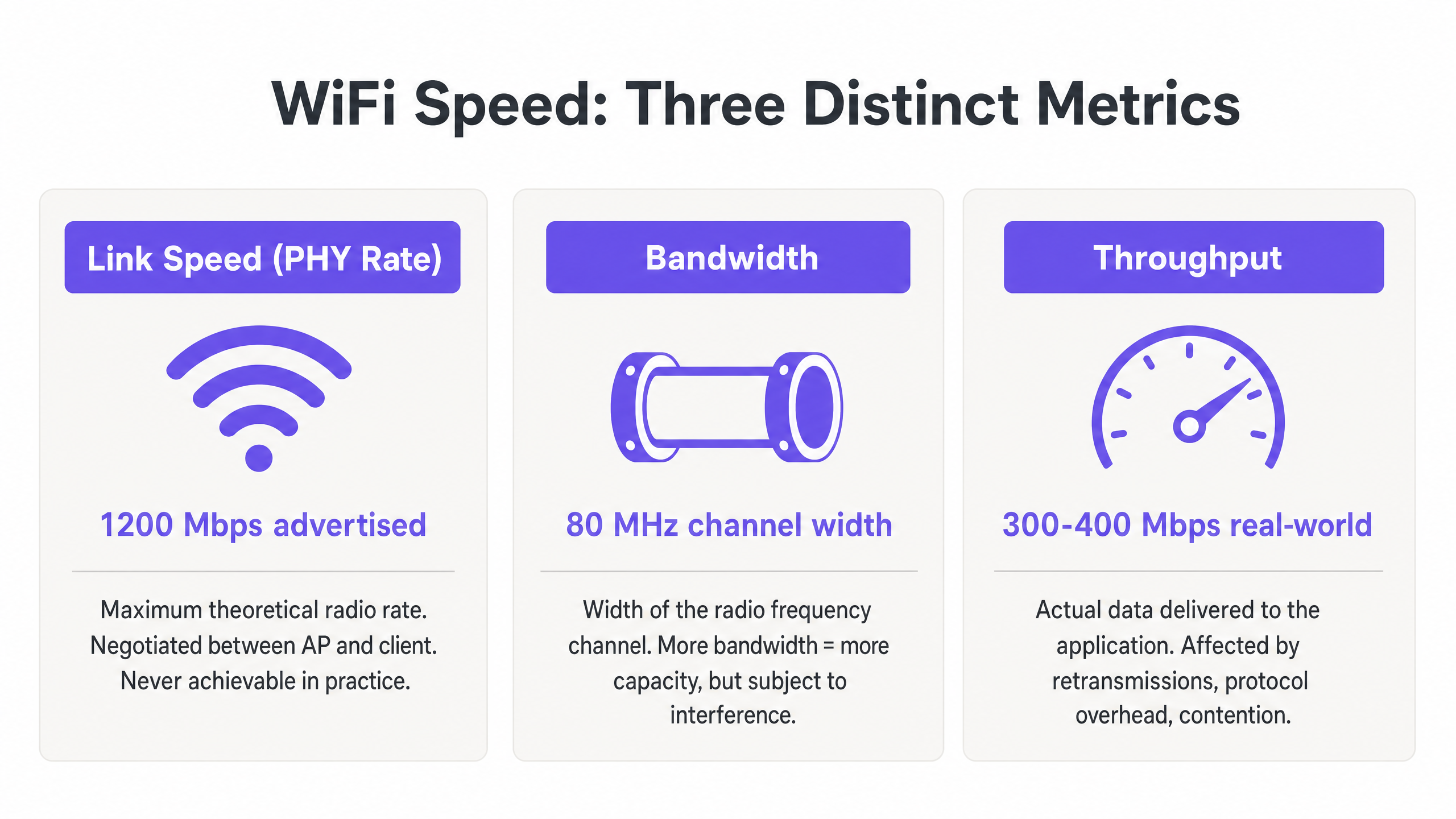
Per i manager IT e gli architetti di rete che implementano WLAN aziendali, la discrepanza tra le velocità WiFi pubblicizzate e l'esperienza utente effettiva è una sfida operativa persistente. La causa principale è quasi sempre un'errata comprensione di tre metriche distinte: link speed (PHY rate), bandwidth e throughput. Mentre i fornitori commercializzano velocità di link teoriche massime — ad esempio, 1200 Mbps su 802.11ax — il throughput effettivo fornito a un'applicazione è tipicamente il 40-60% di tale cifra a causa dell'overhead del protocollo, del funzionamento radio half-duplex e della contesa ambientale.
Questa guida tecnica di riferimento fornisce un framework definitivo per comprendere il significato della velocità WiFi negli ambienti aziendali. Fornisce ai team IT di hotel, catene di vendita al dettaglio e grandi sedi le conoscenze per misurare accuratamente le prestazioni nel mondo reale, progettare per la capacità piuttosto che per la copertura e allineare gli investimenti infrastrutturali con risultati di business misurabili. Spostando l'attenzione dai massimi teorici al throughput sostenuto e all'allocazione ottimale della bandwidth, gli operatori delle sedi possono fornire la connettività affidabile che le moderne piattaforme Guest WiFi e WiFi Analytics richiedono.
Approfondimento Tecnico: Decodifica delle Metriche di Velocità WiFi
Per progettare una WLAN robusta, i professionisti IT devono distinguere tra le capacità teoriche del mezzo RF e la consegna pratica dei payload di dati. Le tre metriche — link speed, bandwidth e throughput — sono spesso confuse nel marketing dei fornitori, nelle discussioni sugli acquisti e persino nei rapporti IT interni. Capire correttamente questo aspetto è fondamentale per ogni altra decisione di ottimizzazione.
Link Speed (PHY Rate): Il Limite Teorico
La link speed, o velocità del Physical Layer (PHY), rappresenta la massima velocità teorica di trasferimento dati tra un Access Point (AP) e un client device a livello radio. Questa velocità viene negoziata dinamicamente in base allo schema di modulazione e codifica (MCS), al numero di spatial streams e al rapporto segnale/rumore (SNR) al momento dell'associazione.
Fondamentalmente, la link speed non è mai raggiungibile nella pratica. Rappresenta il bit rate lordo, inclusi tutti i frame di gestione 802.11, i frame di controllo (RTS/CTS e ACKs) e l'intervallo tra i frame (AIFS/DIFS). Nelle implementazioni aziendali in ambienti Retail o Hospitality , un client che riporta una link speed di 866 Mbps su una rete 802.11ac è in realtà capace di circa 400–500 Mbps di trasferimento dati effettivo in condizioni ideali e isolate — e molto meno in un ambiente condiviso e multi-client.
Bandwidth: La Capacità del Canale RF
La bandwidth si riferisce alla larghezza del canale di radiofrequenza allocato per la trasmissione, tipicamente misurata in Megahertz (MHz). Nelle bande 5 GHz e 6 GHz, i canali possono essere larghi 20, 40, 80 o 160 MHz. Canali più ampi offrono velocità di link potenziali più elevate — raddoppiare la larghezza del canale raddoppia approssimativamente la potenziale velocità dati — ma aumentano anche il rumore di fondo di 3 dB per ogni raddoppio e riducono significativamente il numero di canali non sovrapposti disponibili.
In ambienti ad alta densità come stadi, centri congressi o corridoi di hotel, l'implementazione di canali da 80 MHz porta spesso a una catastrofica interferenza co-canale (CCI). La best practice aziendale impone quindi l'uso di canali da 20 MHz o 40 MHz per massimizzare il riutilizzo spettrale e la capacità complessiva del sistema, piuttosto che inseguire le velocità individuali di picco. Questa è una filosofia di progettazione che privilegia il throughput aggregato su tutti gli utenti rispetto al massimo teorico per un singolo utente.
Throughput: La Misurazione nel Mondo Reale
Il throughput è il dato di payload effettivo consegnato al livello applicativo (Layer 7), misurato in Megabits per secondo (Mbps). Questa è l'unica metrica che conta per l'utente finale, ed è l'unica metrica che dovrebbe guidare le decisioni di progettazione della rete.
Il throughput è fondamentalmente limitato dalla natura half-duplex del WiFi — solo un dispositivo può trasmettere su un dato canale alla volta. Quando più dispositivi competono per il tempo di trasmissione, il throughput diminuisce proporzionalmente. Inoltre, i client legacy che trasmettono a velocità dati inferiori consumano un tempo di trasmissione sproporzionato, penalizzando i client più veloci che condividono lo stesso canale. Comprendere il vero costo del consumo di tempo di trasmissione è fondamentale quando si valuta l'impatto della raccolta dati in background sulla propria WLAN, come approfondito in The Hidden Cost of Telemetry Data on Corporate WLANs .
La tabella seguente riassume la relazione pratica tra queste tre metriche:
| Metrica | Definizione | Valore Tipico (802.11ax) | Cosa Dovrebbero Fare i Team IT |
|---|---|---|---|
| Link Speed (PHY Rate) | Velocità radio teorica lorda | Up to 9.6 Gbps | Utilizzare solo come indicatore di base; mai come obiettivo di performance |
| Bandwidth (Channel Width) | Larghezza del canale RF in MHz | 20, 40, 80, or 160 MHz | Impostare a 40 MHz in ambiente aziendale; 20 MHz in alta densità |
| Throughput | Velocità dati effettiva a livello applicativo | 300–500 Mbps per client (ideal) | Questo è il KPI primario per tutte le valutazioni delle prestazioni WLAN |
Guida all'Implementazione: Misurazione e Ottimizzazione delle Prestazioni
Il passaggio dalla teoria alla pratica richiede una metodologia di misurazione rigorosa e una messa a punto sistematica. I seguenti passaggi riflettono le best practice neutrali rispetto ai fornitori applicabili asu tutte le principali piattaforme WLAN.
Fase 1: Stabilire Baseline Accurate
Non affidarsi a test di velocità internet consumer (come fast.com o Speedtest.net) per misurare le prestazioni della WLAN. Questi test introducono latenza WAN, variabili di routing ISP e colli di bottiglia lato server che sono del tutto estranei alla vostra rete wireless. Distribuire invece un server iPerf3 locale sulla stessa VLAN dell'interfaccia di gestione dell'AP per isolare il segmento RF. Eseguire test di throughput UDP per valutare la capacità grezza del canale e test di throughput TCP per valutare le prestazioni a livello di applicazione — il TCP è altamente sensibile alla perdita di pacchetti e alla latenza, rendendolo un proxy accurato per il comportamento reale delle applicazioni.
Fase 2: Progettare per l'Efficienza dell'Airtime
L'airtime è la risorsa più preziosa in qualsiasi implementazione WiFi. Per massimizzare il throughput in tutta la sede, tre modifiche alla configurazione offrono il maggiore impatto:
Disabilitare le Basse Velocità Base. Disabilitare le velocità 802.11b (1, 2, 5.5, 11 Mbps) e imporre una velocità base minima di 12 Mbps o 24 Mbps. Ciò costringe i client a trasmettere i frame di gestione più velocemente, liberando airtime per i payload di dati. Un singolo frame di gestione inviato a 1 Mbps consuma 54 volte più airtime dello stesso frame inviato a 54 Mbps.
Abilitare l'Airtime Fairness (ATF). Laddove supportato dal fornitore, abilitare l'ATF per allocare un tempo di trasmissione uguale ai client, piuttosto che un numero uguale di pacchetti. Ciò impedisce ai client legacy lenti di monopolizzare il canale a scapito di dispositivi più veloci e moderni.
Ottimizzare le Larghezze di Canale. Impostare di default canali a 20 MHz nella banda 2.4 GHz (sempre canali 1, 6 e 11) e 40 MHz nella banda 5 GHz per implementazioni aziendali ad alta densità. Riservare i canali a 80 MHz solo per ambienti isolati e a bassa densità.

Fase 3: Implementare Autenticazione e Sicurezza Moderne
I protocolli di sicurezza influiscono sul throughput tramite l'overhead di crittografia e la latenza di roaming. Implementare WPA3 dove il parco client lo supporta, o WPA2-Enterprise (IEEE 802.1X) con Fast BSS Transition (802.11r) per minimizzare i ritardi di roaming al di sotto dei 50 ms. Per le reti ospiti, la conformità con GDPR e PCI DSS richiede una robusta segmentazione della rete — il traffico ospite deve essere isolato dall'infrastruttura aziendale e di pagamento tramite VLAN dedicate e policy firewall. Le moderne soluzioni di onboarding che riducono l'attrito dell'autenticazione mantenendo la conformità sono discusse in Come un assistente Wi-Fi abilita l'accesso senza password nel 2026 .
Best Practice e Standard di Settore
I seguenti principi rappresentano il consenso delle raccomandazioni del gruppo di lavoro IEEE 802.11 e l'esperienza di implementazione WLAN aziendale in Sanità , Trasporti e ambienti di grandi dimensioni.
Capacità sulla Copertura. Negli ambienti aziendali moderni, gli AP dovrebbero essere distribuiti per gestire la densità dei client, non solo per fornire un segnale. Un segnale forte (copertura) non garantisce un throughput elevato (capacità) se il canale è congestionato. I due sono obiettivi di ingegneria completamente diversi.
Band Steering. Indirizzare aggressivamente i client dual-band e tri-band verso le bande a 5 GHz e 6 GHz per alleviare la congestione sullo stretto spettro a 2.4 GHz. La banda a 2.4 GHz offre solo tre canali non sovrapposti (1, 6, 11) ed è soggetta a significative interferenze da dispositivi non-WiFi.
Soglie SNR Minime. Configurare le radio degli AP per rifiutare le associazioni client al di sotto di una soglia SNR minima (tipicamente 20 dB). Ciò impedisce ai client distanti e deboli di associarsi e trasmettere a basse velocità MCS, il che consumerebbe un airtime eccessivo.
Audit RF Regolari. Condurre analisi dello spettro e test di throughput attivi almeno trimestralmente, e immediatamente dopo qualsiasi cambiamento significativo all'ambiente fisico (nuove partizioni, apparecchiature AV o modifiche agli inquilini). L'ambiente RF è dinamico; un piano di canali che funzionava al momento dell'implementazione potrebbe essere subottimale sei mesi dopo.
Risoluzione dei Problemi e Mitigazione del Rischio
Quando il throughput si degrada, i team IT devono diagnosticare l'ambiente RF sistematicamente piuttosto che ricorrere immediatamente agli aggiornamenti hardware. La maggior parte dei problemi di prestazioni delle WLAN aziendali sono problemi di configurazione e progettazione, non limitazioni hardware.
Alti Tassi di Ritrasmissione. Un tasso di ritrasmissione superiore al 10% indica tipicamente interferenze RF, problemi di nodi nascosti o un SNR client scarso. Utilizzare strumenti di analisi dello spettro per identificare le fonti di interferenza non-WiFi — forni a microonde, apparecchiature AV e reti vicine sono i colpevoli comuni negli ambienti di ospitalità e vendita al dettaglio.
Interferenza Co-Canale (CCI). Se più AP sullo stesso canale possono sentirsi a -85 dBm o più forte, condividono lo stesso dominio di collisione, riducendo drasticamente il throughput per tutti i client su quel canale. Mitigare questo riducendo la potenza di trasmissione degli AP, restringendo le larghezze di canale e assicurando che gli algoritmi di assegnazione dinamica dei canali (DCA) funzionino correttamente.
Client Sticky. I client che non riescono a effettuare il roaming da un AP distante a uno più vicino mantengono un SNR basso, costringendo l'AP a utilizzare una bassa velocità MCS e consumando un airtime eccessivo. Mitigare con soglie RSSI minime per l'associazione, 802.11v BSS Transition Management e 802.11r Fast Roaming.
Problemi con i Driver Client. Driver wireless obsoleti sui dispositivi degli utenti finali possono causare una negoziazione MCS errata, il mancato utilizzo degli stream spaziali MIMO o un comportamento aggressivo di risparmio energetico che interrompe il throughput. Mantenere una policy di gestione dei dispositivi client che includa gli standard di versione dei driver wireless.
ROI e Impatto sul Business
Ottimizzare il WiFi per il throughput piuttosto che per la velocità di collegamento teorica ha un impatto diretto sui profitti in ogni settore verticale. Negli hub di Trasporti e nelle grandi sedi, la connettività affidabile è essenziale per l'efficienza operativa — dai sistemi di punto vendita mobile (mPOS) alla segnaletica digitale e al controllo degli accessi.
Per gli operatori di sedi, le reti ad alta capacità consentono servizi e analisi avanzati basati sulla posizione. Garantire una connettività coerente e affidabile è un prerequisito per funzionalità come quelle introdotte in Purple lancia la modalità Mappe Offline per una navigazione fluida e sicura verso gli hotspot WiFi , che migliorano l'esperienza degli ospiti e promuovono un coinvolgimento misurabile. L'espansione di Purple nel settore pubblico, dettagliata in Purple nomina Iain Fox VP Growth – Settore Pubblico per promuovere l'inclusione digitale e l'innovazione delle Smart City , sottolinea ulteriormente l'importanza di un'infrastruttura WiFi pubblica affidabile e ad alta capacità come base per i servizi delle smart city.
Il caso aziendale per una progettazione WLAN focalizzata sulla capacità è semplice: una rete che offre 200 Mbps costanti per client durante le ore di punta è più preziosa di una che offre una velocità di collegamento di 866 Mbps con l'85% di utilizzo del tempo di trasmissione e prestazioni imprevedibili nel mondo reale. Allineando le metriche IT — capacità, utilizzo del tempo di trasmissione, tasso di ritrasmissione — con i risultati aziendali — punteggi di soddisfazione degli ospiti, affidabilità delle transazioni mPOS, tempo di attività operativa — i leader IT possono giustificare gli investimenti in infrastrutture e dimostrare un ROI chiaro e misurabile.
Definizioni chiave
Link Speed (PHY Rate)
The maximum theoretical physical layer data rate negotiated between a client and an AP, measured in Mbps. Determined by MCS index, spatial streams, and channel width.
Frequently cited in vendor marketing and procurement documents. IT teams must understand this is a gross rate that includes massive protocol overhead and is never achievable as application throughput.
Throughput
The actual rate of successful payload data delivery over a communication channel to the application layer, measured in Mbps.
The primary KPI for any WLAN performance assessment. The only metric that accurately reflects end-user experience and application performance.
Bandwidth (RF Channel Width)
The width of the frequency spectrum allocated for a transmission channel, typically 20, 40, 80, or 160 MHz in the 5 GHz band.
Determines the potential capacity of the channel. Wider bandwidths increase peak link speed but reduce the number of non-overlapping channels and increase susceptibility to interference in dense deployments.
Co-Channel Interference (CCI)
Performance degradation caused when multiple APs operate on the same frequency channel and can detect each other's transmissions, forcing them to share airtime via the CSMA/CA contention mechanism.
The primary cause of poor throughput in dense enterprise deployments. Mitigated by proper channel planning, reduced transmit power, and narrower channel widths.
Airtime Utilisation
The percentage of time a specific RF channel is occupied with transmissions (data, management, or control frames).
A critical operational metric. Sustained utilisation above 70–80% indicates severe congestion and impending throughput collapse. Should be monitored per-radio and per-SSID.
Half-Duplex
A communication mode where data can be transmitted in both directions, but only one direction at a time on a shared medium.
The fundamental characteristic of WiFi that limits throughput to significantly below the theoretical link speed. Unlike wired Ethernet (full-duplex), WiFi requires all devices to take turns transmitting.
Spatial Streams (MIMO)
Multiple independent data signals transmitted simultaneously using Multiple Input Multiple Output (MIMO) antenna technology, increasing throughput without requiring wider bandwidth.
A key differentiator between 802.11ac (up to 8 spatial streams) and 802.11ax (Wi-Fi 6). Effective only when both the AP and client device support multiple antennas.
Basic Rates
The mandatory data rates that all clients must support to associate with a BSS. Management and control frames are transmitted at the lowest enabled basic rate.
Disabling low basic rates (1, 2, 5.5, 11 Mbps) is a standard and highly effective IT configuration practice. A frame sent at 1 Mbps consumes 54 times more airtime than the same frame at 54 Mbps.
MCS (Modulation and Coding Scheme)
An index value that defines the combination of modulation technique (e.g., 256-QAM, 1024-QAM) and forward error correction coding rate used for a given transmission.
Higher MCS indices deliver higher throughput but require a stronger signal-to-noise ratio. The AP and client negotiate the highest feasible MCS based on current RF conditions.
Esempi pratici
A 400-room hotel is experiencing guest complaints about slow WiFi speeds during the evening peak (7 PM – 10 PM). The IT manager notes that the APs are reporting link speeds of 866 Mbps, but guests are struggling to stream video. The network uses 80 MHz channels on the 5 GHz band with APs deployed in corridors at maximum transmit power.
- Conduct an airtime utilisation assessment during peak hours using the WLAN controller's built-in analytics or a dedicated tool such as Ekahau Sidekick. Expect to find utilisation above 80% on the primary 5 GHz channels, confirming Co-Channel Interference (CCI). 2. Reconfigure the WLAN controller to reduce channel widths on the 5 GHz band from 80 MHz to 40 MHz. This doubles the number of available non-overlapping channels from 6 to 12 in the UNII-1/UNII-3 bands, significantly reducing CCI. 3. Reduce AP transmit power to approximately 11–14 dBm to shrink cell sizes and reduce the number of APs that can hear each other on the same channel. 4. Enable dynamic channel assignment (DCA) to allow the controller to optimise channel allocation automatically. 5. Implement per-client bandwidth throttling (e.g., 15 Mbps downstream per device) to prevent individual users from monopolising the internet uplink during peak hours.
A large retail chain is deploying mobile Point-of-Sale (mPOS) tablets across 50 stores. The tablets require reliable, low-latency connections for payment processing, but are frequently dropping sessions when staff move between aisles. The WLAN uses WPA2-Personal with default basic rates enabled.
- Implement IEEE 802.11r (Fast BSS Transition) on the corporate mPOS SSID to reduce roaming authentication delays from 300–500 ms to under 50 ms. This is critical for session-sensitive payment applications. 2. Adjust the AP minimum mandatory basic rate to 12 Mbps. This reduces the effective cell size, encouraging tablets to roam to closer APs sooner rather than maintaining a weak connection to a distant AP (sticky client behaviour). 3. Migrate the mPOS SSID from WPA2-Personal to WPA2-Enterprise (802.1X) with certificate-based authentication to meet PCI DSS requirements for cardholder data environments. 4. Apply WMM (Wi-Fi Multimedia) QoS tags to the mPOS SSID, prioritising traffic in the Voice or Video queue to protect throughput during periods of high guest network usage. 5. Implement 802.11k (Neighbour Reports) and 802.11v (BSS Transition Management) to assist tablets in identifying and roaming to optimal APs proactively.
Domande di esercitazione
Q1. You are designing the WLAN for a high-density university lecture theatre with 300 seats. Your goal is to maximise aggregate throughput for all users simultaneously. The venue has 8 APs deployed in the ceiling. Should you configure the 5 GHz radios to use 20 MHz, 40 MHz, or 80 MHz channel widths?
Suggerimento: Consider the number of non-overlapping channels available in the 5 GHz UNII-1 and UNII-3 bands, and the impact of Co-Channel Interference in a single open room with multiple APs.
Visualizza risposta modello
Use 20 MHz channels. In a high-density, single-room environment with 8 APs, you need each AP to operate on a distinct, non-overlapping channel to avoid CCI. The 5 GHz band offers approximately 24 non-overlapping 20 MHz channels (in regions with full UNII band access), but only 6 non-overlapping 40 MHz channels and 3 non-overlapping 80 MHz channels. With 8 APs using 80 MHz channels, at least 5 APs would be sharing channels, creating severe CCI. By using 20 MHz channels, you can assign unique channels to all 8 APs, allowing them to transmit simultaneously without contention. The individual link speed per client will be lower, but the aggregate throughput across all 300 users will be dramatically higher.
Q2. A client complains that their new 802.11ax (Wi-Fi 6) laptop only achieves 480 Mbps on a local iPerf3 test, despite Windows reporting a link speed of 1.2 Gbps. The client believes the AP is faulty. How do you assess and explain this situation?
Suggerimento: Apply the Rule of Half and consider the relationship between PHY rate and TCP throughput in a half-duplex medium.
Visualizza risposta modello
The AP is almost certainly functioning correctly. The 1.2 Gbps is the negotiated Link Speed (PHY rate) — the gross theoretical radio rate. Because WiFi is half-duplex, and because the 802.11 protocol requires significant overhead (management frames, ACKs, inter-frame spacing), actual TCP throughput is typically 40–60% of the link speed. 480 Mbps from a 1.2 Gbps link represents a 40% efficiency ratio, which is within the expected range and indicates the network is performing well. To confirm, check the retransmission rate (should be below 5%) and airtime utilisation (should be below 50% for a single-client test). If both are healthy, the result is excellent and the AP should not be replaced.
Q3. During a site survey in a busy retail warehouse, you notice the airtime utilisation on channel 6 (2.4 GHz) is consistently at 88%, but there are only 6 active clients connected to the AP. The AP is a modern 802.11ax device. What are the two most likely causes, and what is the remediation for each?
Suggerimento: Think about how legacy data rates affect airtime consumption, and consider sources of non-WiFi interference common in warehouse environments.
Visualizza risposta modello
Cause 1: Legacy basic rates are enabled. If the AP is transmitting management frames (beacons, probe responses) at 1 Mbps, each frame takes 54 times longer than at 54 Mbps, consuming enormous amounts of airtime even with few clients. Remediation: Disable 802.11b rates and set the minimum basic rate to 12 Mbps or 24 Mbps. Cause 2: Non-WiFi interference in the 2.4 GHz band. Warehouses commonly contain microwave ovens, Bluetooth devices, and older industrial wireless equipment that generate broadband interference in the 2.4 GHz band, artificially inflating airtime utilisation figures. Remediation: Conduct a spectrum analysis using a tool such as Ekahau Sidekick or a dedicated spectrum analyser to identify the interference source, and where possible migrate clients to the 5 GHz band.