Como Mudar os Canais WiFi para Prevenir Interferência
Este guia técnico abrangente oferece a gerentes de TI, arquitetos de rede e diretores de operações de locais uma abordagem definitiva e passo a passo para identificar fontes de interferência WiFi e mudar estrategicamente os canais WiFi para eliminá-las. Ele abrange o planejamento de bandas de 2.4 GHz e 5 GHz, análise de espectro, Gerenciamento de Recursos de Rádio e considerações de DFS, fundamentado nos padrões IEEE 802.11 e cenários de implantação do mundo real. A implementação dessas estratégias proporciona melhorias mensuráveis na taxa de transferência da rede, estabilidade do cliente e ROI da infraestrutura, sem exigir despesas de capital em novo hardware.
Ouça este guia
Ver transcrição do podcast
Resumo Executivo
Para ambientes corporativos — desde grandes locais de Hospitalidade até espaços densos de Varejo — o WiFi confiável não é mais um benefício; é uma infraestrutura crítica. A interferência continua sendo a principal causa de quedas de conexão, alta latência e baixa taxa de transferência, impactando diretamente tanto a eficiência operacional quanto a experiência do Guest WiFi . Este guia oferece a arquitetos de rede e gerentes de TI uma abordagem definitiva e passo a passo para identificar fontes de interferência e mudar estrategicamente os canais WiFi para mitigá-las.
Ao implementar as melhores práticas neutras em relação a fornecedores para o gerenciamento de espectro, as organizações podem maximizar o ROI de sua infraestrutura, garantir o roaming contínuo do cliente e suportar a crescente densidade de dispositivos IoT e de usuários sem comprometer a segurança ou os padrões de conformidade, incluindo PCI DSS e GDPR. O princípio central é direto: a interferência é um problema de gerenciamento de espectro, não um problema de hardware. A configuração correta da infraestrutura existente, na maioria dos casos, resolverá problemas de desempenho que as organizações atribuem erroneamente à densidade insuficiente de APs ou a equipamentos desatualizados.
Análise Técnica Detalhada
Compreender a camada física das redes IEEE 802.11 é essencial antes de fazer qualquer alteração de configuração. O espectro de radiofrequência (RF) é um meio compartilhado governado pelo protocolo CSMA/CA (Carrier Sense Multiple Access with Collision Avoidance), e a interferência geralmente se enquadra em duas categorias distintas: Interferência Co-Canal (CCI) e Interferência de Canal Adjacente (ACI).
Interferência Co-Canal (CCI) ocorre quando múltiplos pontos de acesso ou clientes transmitem exatamente no mesmo canal. Embora os protocolos 802.11 usem CSMA/CA para gerenciar isso — dispositivos escutam antes de transmitir — o CCI excessivo força os dispositivos a esperar por tempo de transmissão livre, reduzindo drasticamente a taxa de transferência e aumentando a latência. É fundamentalmente um problema de congestionamento, e não um ruído RF verdadeiro, e o mecanismo CSMA/CA pode lidar com isso até certo ponto de forma elegante.
Interferência de Canal Adjacente (ACI) é muito mais destrutiva. Acontece quando os APs operam em frequências sobrepostas — por exemplo, canais 2 e 4 na banda de 2.4 GHz. Como as transmissões se sobrepõem, mas não podem ser decodificadas pelo CSMA/CA, elas são tratadas como ruído puro, elevando o piso de ruído e causando perda de pacotes e retransmissões. Em um local movimentado, a ACI pode reduzir a taxa de transferência efetiva em 60–70% e é o erro de configuração mais comum encontrado em implantações corporativas.
O Dilema dos 2.4 GHz
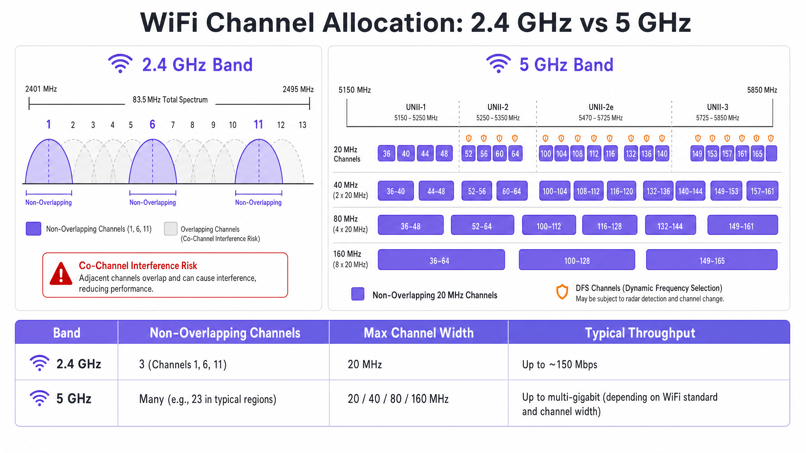
A banda de 2.4 GHz oferece melhor alcance e penetração em paredes, mas é severamente limitada por um espectro restrito — aproximadamente 83.5 MHz no total. Embora existam de 11 a 14 canais, dependendo do domínio regulatório, apenas três são verdadeiramente não sobrepostos: Canais 1, 6 e 11. Usar qualquer outro canal em uma implantação multi-AP garante ACI. Além disso, esta banda está lotada de interferências não-WiFi, incluindo dispositivos Bluetooth, fornos de micro-ondas e telefones sem fio DECT operando no mesmo espectro. Para uma análise detalhada de como o Bluetooth Low Energy coexiste com a infraestrutura WiFi, consulte nosso guia sobre BLE Low Energy Explicado para Empresas . Para um tratamento mais amplo da seleção de banda de frequência, consulte Frequências Wi-Fi: Um Guia para Frequências Wi-Fi em 2026 .
A Vantagem dos 5 GHz
A banda de 5 GHz oferece significativamente mais espectro, fornecendo numerosos canais de 20 MHz não sobrepostos nas sub-bandas UNII-1, UNII-2, UNII-2e e UNII-3. Esta banda é o padrão correto para o tráfego de clientes corporativos. No entanto, ela introduz duas complexidades principais: compensações de agregação de canais e Seleção Dinâmica de Frequência (DFS).
A agregação de canais — combinando canais de 20 MHz em larguras de 40, 80 ou 160 MHz — aumenta a taxa de transferência de pico para um único cliente, mas reduz o número total de canais independentes disponíveis. Em ambientes de alta densidade, isso causa CCI severa. Os canais DFS (principalmente UNII-2 e UNII-2e) exigem que os APs monitorem sinais de radar e desocupem imediatamente o canal se detectados, causando desconexões de clientes. Esta é uma consideração crítica para locais próximos a aeroportos, estações meteorológicas ou instalações militares.
Guia de Implementação
Mudar os canais WiFi nunca deve ser baseado em suposições. Requer uma abordagem sistemática e orientada por dados.
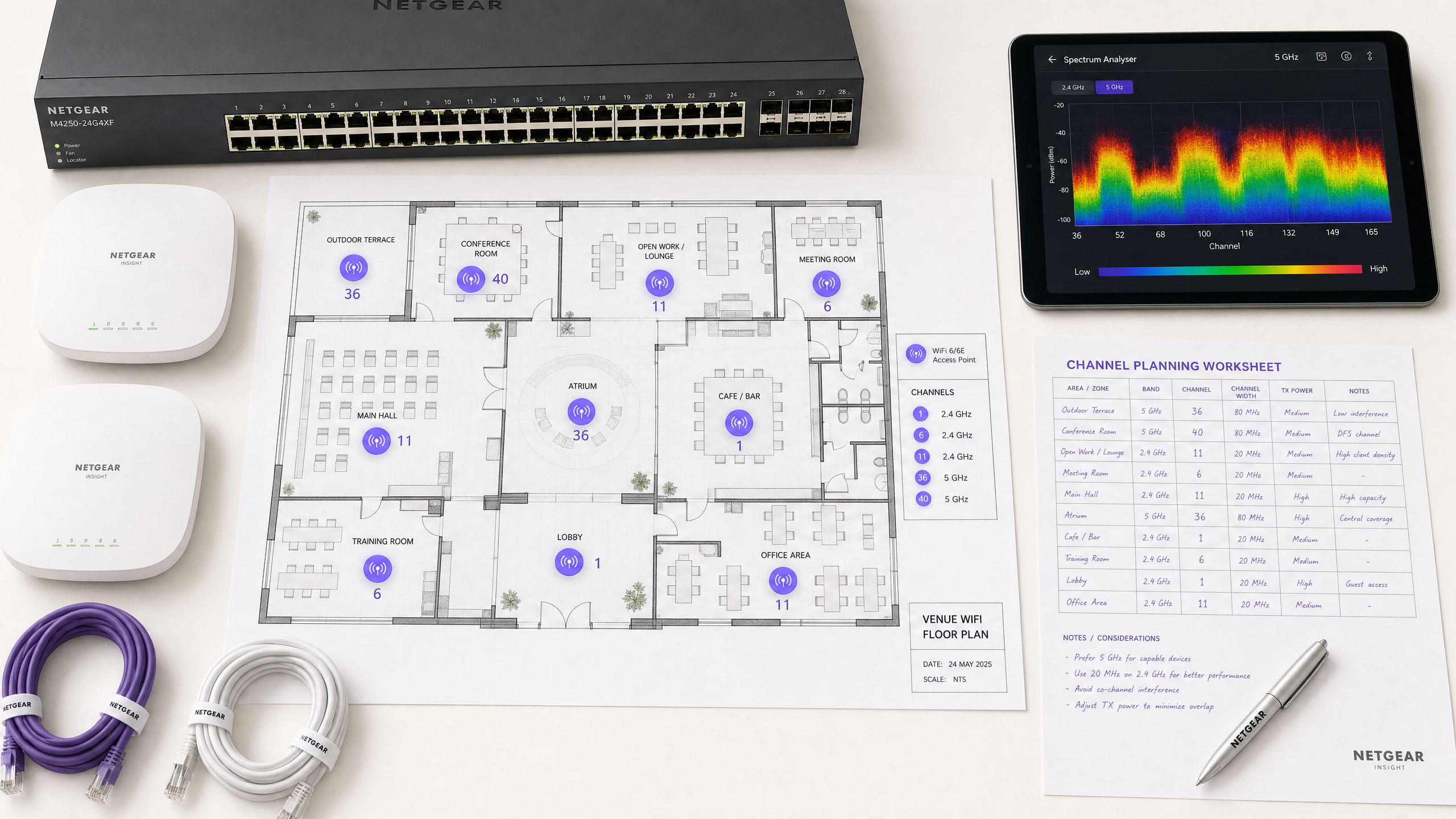
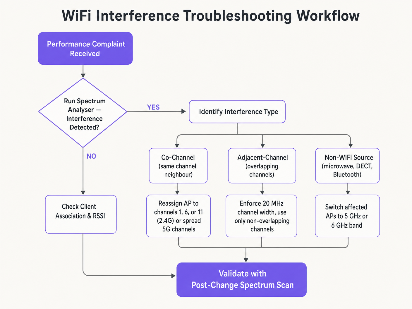
Passo 1: Realize uma Análise de Espectro
Antes de fazer qualquer alteração de configuração, estabeleça uma linha de base empírica. Implante um analisador de espectro — seja hardware dedicado ou as ferramentas integradas em seu controlador WLAN corporativo — para pesquisar o ambiente RF em ambas as bandas. Documente o seguinte: APs desonestos ou vizinhos e suas atribuições de canal, o piso de ruído em cada canal, a presença de fontes de interferência não-WiFi e os níveis atuais de potência de transmissão do AP. Esta linha de base é seu ponto de referência para medir o impacto das mudanças subsequentes.
Passo 2: Formule um Plano de Canais
Para a banda de 2.4 GHz: Restrinja o pool de canais estritamente aos canais 1, 6 e 11. Defina todas as larguras de canal para 20 MHz — isso não é negociável. Se a densidade de APs for alta o suficiente para causar CCI significativa mesmo com o esquema 1-6-11, considere desabilitar o rádio de 2.4 GHz em APs alternados em um padrão de tabuleiro de xadrez, efetivamente reduzindo pela metade a densidade de APs de 2.4 GHz enquanto mantém a cobertura através dos APs restantes.
Para a banda de 5 GHz: Maximize o uso dos canais não sobrepostos disponíveis. Em implantações de alta densidade — centros de conferências, estádios, hubs de Transporte — force larguras de canal de 20 MHz para maximizar o número de canais independentes. Aumente para 40 MHz apenas em áreas de baixa densidade onde a CCI não é uma preocupação. Avalie cuidadosamente a inclusão de canais DFS com base na sua localização específica e proximidade a fontes de radar. Consulte a lista de disponibilidade de canais da sua autoridade reguladora nacional para a sua região específica.
Passo 3: Configurar Pontos de Acesso
Acesse seu controlador de LAN sem fio (WLC) ou painel de gerenciamento em nuvem para aplicar o plano de canais. A maioria das plataformas corporativas oferece recursos de Gerenciamento de Recursos de Rádio (RRM) ou Auto-RF que atribuem dinamicamente canais e níveis de potência.
| Abordagem | Melhor para | Risco |
|---|---|---|
| Plano Estático Manual | Locais complexos, de alta densidade ou adjacentes a radar | Requer nova pesquisa periódica conforme o ambiente muda |
| Auto-RF / RRM | Implantações mais simples, de menor densidade | Pode causar instabilidade de canal em ambientes RF voláteis |
| Híbrido | A maioria das implantações corporativas | Requer configuração cuidadosa de restrições |
Em ambientes altamente complexos, um plano de canais estático manual baseado em uma pesquisa preditiva geralmente proporciona melhor estabilidade do que depender apenas do Auto-RF. A potência de transmissão deve ser ajustada em paralelo — reduza a potência de TX do AP para 10–14 dBm em 5 GHz em implantações densas para diminuir o tamanho das células e reduzir a interferência entre APs.
Passo 4: Validar e Monitorar
Após aplicar as alterações, conduza uma pesquisa de validação pós-implementação para validar o novo plano de canais. Monitore os principais indicadores de desempenho (KPIs) por meio de sua plataforma de WiFi Analytics , focando nas taxas de repetição, utilização do tempo de antena por AP, contagens de associação de clientes e comportamento de roaming. Um ambiente RF bem ajustado deve apresentar taxas de repetição abaixo de 10% e utilização do tempo de antena abaixo de 70% durante os períodos de pico.
Melhores Práticas
Force larguras de 20 MHz em alta densidade. Em ambientes como centros de conferências ou estádios, priorize a capacidade — mais canais não sobrepostos — em vez do throughput máximo de cliente único de canais mais amplos. O desempenho agregado da rede será significativamente maior.
Implemente o band steering agressivamente. Configure o band steering para afastar clientes compatíveis com 5 GHz da banda congestionada de 2.4 GHz. A maioria dos controladores empresariais modernos suporta isso nativamente. Reserve 2.4 GHz para dispositivos IoT e hardware legado que não podem operar em 5 GHz.
Desative as taxas de dados legadas. Desative as taxas de dados 802.11b (1, 2, 5.5, 11 Mbps) em todos os SSIDs. Essas taxas legadas consomem tempo de antena desproporcional e atrasam toda a rede. Definir uma taxa de dados mínima de 12 ou 24 Mbps força os clientes a fazerem roaming mais cedo e reduz a sobrecarga do quadro de gerenciamento.
Agende auditorias de RF regulares. O ambiente de RF é dinâmico. Novas redes vizinhas, modificações de edifícios e novos equipamentos alteram o cenário de interferência. Agende auditorias de RF trimestrais para manter seu plano de canais atualizado.
Integre segurança e gerenciamento de rede. Garanta que a detecção e mitigação de APs não autorizados estejam ativadas para evitar que dispositivos não autorizados causem interferência ou violações de segurança. Para um contexto de segurança de rede mais amplo, incluindo filtragem de conteúdo em redes de convidados, revise O que é Filtragem DNS? Como Bloquear Conteúdo Nocivo em WiFi de Convidados . Para estratégias de otimização específicas para escritórios, consulte Wi Fi de Escritório: Otimize Sua Rede Wi-Fi Moderna de Escritório .
Solução de Problemas e Mitigação de Riscos
Sintoma: Sinal forte, throughput fraco. Esta é a marca registrada da Interferência Co-Canal. O piso de ruído é baixo, mas o tempo de antena está saturado. Audite as atribuições de canais e a potência de transmissão do AP. Reduza a potência de TX e force larguras de canal de 20 MHz para liberar tempo de antena e melhorar a reutilização espacial.
Sintoma: Desconexões aleatórias de clientes em zonas específicas. Verifique os logs de eventos DFS imediatamente. Se os APs nessa zona estiverem em canais UNII-2 ou UNII-2e e estiverem próximos a uma fonte de radar, eles serão legalmente obrigados a desocupar o canal, desconectando os clientes. Exclua esses canais DFS específicos do plano de canais para as zonas afetadas.
Sintoma: O plano de canais continua mudando automaticamente. Isso é instabilidade de canal causada por um algoritmo Auto-RF excessivamente sensível reagindo a interferências transitórias. Restrinja as configurações de sensibilidade do RRM, aumente o temporizador de retenção ou migre para um plano de canais estático baseado em dados de pesquisa.
Sintoma: Desempenho fraco em áreas específicas apesar de bom sinal. Interferência não-WiFi de fornos de micro-ondas, telefones DECT ou equipamentos industriais pode estar elevando o piso de ruído. Um analisador de espectro identificará essas fontes. A remediação é remover a fonte ou migrar os APs afetados para a banda de 5 GHz ou 6 GHz, que é imune à maioria dos interferentes não-WiFi de 2.4 GHz.
ROI e Impacto nos Negócios
Otimizar os canais WiFi é uma atualização de infraestrutura de custo zero que gera retornos imediatos e mensuráveis. Organizações que implementam um planejamento adequado de canais RF geralmente relatam uma redução de 30–40% nos tickets de helpdesk relacionados a WiFi no primeiro trimestre. Em ambientes de Saúde , um ambiente RF devidamente ajustado garante o fluxo ininterrupto de dados de telemetria críticos e suporta a conformidade com os requisitos de comunicação de dispositivos clínicos. No Varejo , garante a operação contínua de sistemas de ponto de venda móveis, análises de localização precisas e aplicativos confiáveis de gerenciamento de estoque.
Do ponto de vista de despesas de capital, o planejamento correto de canais frequentemente elimina a necessidade percebida de hardware AP adicional. Muitas organizações que acreditam ter uma densidade de APproblema de qualidade na verdade têm um problema de planejamento de canais. Resolver a configuração de RF primeiro — antes de adquirir hardware adicional — é uma prática padrão em qualquer avaliação de rede rigorosa. Um ambiente de RF devidamente ajustado também estende o ciclo de vida operacional da infraestrutura existente, adiando ciclos caros de atualização de hardware e proporcionando um retorno direto e quantificável sobre o investimento de capital existente.
Definições principais
Co-Channel Interference (CCI)
Interference that occurs when multiple access points or client devices transmit on the exact same frequency channel simultaneously.
Managed by CSMA/CA, but causes congestion and reduced throughput when excessive. The primary symptom is high airtime utilisation with low throughput.
Adjacent-Channel Interference (ACI)
Interference caused by devices transmitting on overlapping but non-identical frequency channels, creating RF noise that CSMA/CA cannot decode or manage.
More destructive than CCI. Raises the noise floor, causes packet loss, and forces retransmissions. Caused by using channels other than 1, 6, and 11 on 2.4 GHz.
Dynamic Frequency Selection (DFS)
An IEEE 802.11h mechanism that requires WiFi access points to monitor for radar signals on certain 5 GHz channels and immediately vacate the channel if radar is detected.
Affects UNII-2 and UNII-2e channels. Critical consideration for venues near airports, weather stations, or military sites, where frequent radar detection causes client disconnections.
Radio Resource Management (RRM)
Automated algorithms within enterprise WLAN controllers that dynamically adjust channel assignments and transmit power levels based on real-time RF conditions.
Useful for adapting to changing RF environments, but can cause 'channel churn' — frequent channel changes — in volatile environments, disrupting client connectivity.
Channel Bonding
The process of combining multiple adjacent 20 MHz channels into wider 40, 80, or 160 MHz channels to increase peak single-client throughput.
Reduces the total number of available non-overlapping channels, increasing CCI risk in dense deployments. Should be avoided in high-density enterprise environments.
Band Steering
A WLAN controller feature that encourages dual-band capable client devices to associate with the 5 GHz band rather than the congested 2.4 GHz band.
Essential for load balancing in enterprise deployments. Preserves the limited 2.4 GHz spectrum for IoT devices and legacy hardware that cannot operate on 5 GHz.
CSMA/CA
Carrier Sense Multiple Access with Collision Avoidance. The medium access control protocol used by IEEE 802.11 WiFi, requiring devices to listen for clear airtime before transmitting.
The mechanism that governs how WiFi devices share the RF medium. High CCI forces devices to wait longer for clear airtime, directly reducing throughput and increasing latency.
Noise Floor
The aggregate level of background RF energy present in a given frequency band, measured in dBm. A higher noise floor reduces the effective Signal-to-Noise Ratio (SNR) for WiFi transmissions.
Raised by ACI, non-WiFi interference, and poor channel planning. A high noise floor forces devices to use lower modulation schemes and data rates, reducing throughput.
Spatial Reuse
The ability of multiple access points to simultaneously transmit on the same channel without interfering with each other, enabled by physical separation and appropriate transmit power levels.
The fundamental mechanism that allows high-density WiFi networks to scale. Maximised by reducing AP transmit power and using the minimum necessary channel widths.
Exemplos práticos
A 200-room hotel is experiencing widespread complaints of slow WiFi during the evening peak. The current deployment uses 40 MHz channels on the 2.4 GHz band across 80 APs, and Auto-RF is enabled. The WLAN controller logs show frequent channel changes throughout the evening.
Phase 1 — Immediate remediation: Reconfigure all 2.4 GHz radios to 20 MHz channel widths immediately. Restrict the 2.4 GHz channel pool to channels 1, 6, and 11 only within the controller. This alone will eliminate ACI across the deployment.
Phase 2 — Stabilise Auto-RF: Review the Auto-RF event logs. If APs are changing channels more than once per hour, the algorithm is reacting to transient interference. Increase the RRM hold-down timer and reduce the sensitivity threshold. If churn persists, migrate to a static channel plan.
Phase 3 — Band steering: Enable aggressive band steering to push dual-band devices to 5 GHz. This reduces 2.4 GHz load significantly during peak periods.
Phase 4 — Validation: Deploy a spectrum analyser post-change and monitor retry rates and airtime utilisation via the WiFi analytics dashboard for 48 hours to confirm improvement.
A large retail chain has deployed APs every 12 metres across a 4,000 sq metre distribution centre. Even on the 5 GHz band using 20 MHz channels, CCI is high, throughput is poor, and mobile scanning devices are experiencing frequent disconnections during peak shift hours.
Step 1 — Audit transmit power: The APs are almost certainly configured at maximum TX power (typically 20–23 dBm). At 12-metre spacing, this creates massive cell overlap. Reduce TX power to 10–12 dBm on 5 GHz to shrink cell sizes and reduce inter-AP interference.
Step 2 — Disable legacy data rates: Disable all 802.11b/g data rates below 12 Mbps. This forces scanning devices to roam to the nearest AP rather than staying associated with a distant AP at a low data rate, which consumes disproportionate airtime.
Step 3 — Review channel plan: Ensure the 5 GHz channel plan uses the maximum number of non-overlapping channels available. With high AP density, every unique channel matters.
Step 4 — Validate with post-change survey: Conduct a walkthrough survey with a spectrum analyser to confirm reduced inter-AP overlap and improved SNR across the floor.
Questões práticas
Q1. You are deploying a new wireless network in a multi-tenant office building. Your spectrum scan shows heavy utilisation on channels 1, 6, and 11 from neighbouring tenants. A junior engineer suggests using channels 3, 8, and 13 to 'avoid the congestion'. How do you respond, and what is the correct configuration?
Dica: Consider the difference between Co-Channel Interference (CCI) and Adjacent-Channel Interference (ACI), and which is more harmful to network performance.
Ver resposta modelo
The junior engineer's suggestion is incorrect and would cause severe performance degradation. Channels 3, 8, and 13 overlap with channels 1, 6, and 11 respectively, which would introduce Adjacent-Channel Interference — the most destructive form of WiFi interference. ACI manifests as pure RF noise that CSMA/CA cannot manage, causing packet loss and retransmissions. The correct configuration is to deploy on channels 1, 6, and 11. While this will cause Co-Channel Interference with the neighbouring tenants, CSMA/CA can handle CCI gracefully by having devices take turns. The aggregate performance will be significantly better than with ACI.
Q2. A stadium deployment is using 80 MHz channels on the 5 GHz band to advertise 'Gigabit WiFi' speeds during events. Users report slow loading times, frequent disconnections, and poor video streaming quality during peak occupancy. The AP hardware is modern WiFi 6 equipment. What is the architectural flaw, and what is the remediation?
Dica: Evaluate the trade-off between peak single-client throughput and overall network capacity in a high-density environment.
Ver resposta modelo
The architectural flaw is the use of 80 MHz channel widths in a high-density environment. Each 80 MHz channel bonds four 20 MHz channels together, drastically reducing the total number of non-overlapping channels available across the deployment. With many APs forced to reuse the same wide channels, Co-Channel Interference becomes severe. The solution is to reduce channel widths to 20 MHz across all APs. This increases the number of independent channels available, reduces CCI, and significantly improves aggregate network capacity. The peak throughput per client will decrease, but the number of clients that can be served simultaneously — and the quality of their experience — will increase substantially.
Q3. Your hospital network experiences intermittent client disconnections affecting medical devices in wards near the hospital's rooftop helipad. The affected APs are configured to use channels 52, 56, 60, and 64. What is the most likely cause, and what is the correct remediation?
Dica: Consider the regulatory requirements for the specific 5 GHz channels in use and what systems operate near a helipad.
Ver resposta modelo
Channels 52, 56, 60, and 64 are UNII-2 DFS channels. The helicopters using the helipad, or associated aviation radar systems, are likely triggering DFS radar detection events on the APs in that zone. When radar is detected, the APs are legally required to immediately vacate those channels, causing client disconnections. The correct remediation is to exclude all DFS channels from the channel plan for APs in the zones near the helipad. Reconfigure those APs to use UNII-1 channels (36, 40, 44, 48) or UNII-3 channels (149, 153, 157, 161, 165), which are not subject to DFS requirements.