Resolução de Interferência Co-Canal em Implementações Empresariais
Este guia de referência técnica fornece a arquitetos de rede e diretores de TI estratégias acionáveis para identificar, mitigar e resolver a interferência co-canal em ambientes empresariais de alta densidade. Abrange princípios de design de RF, estratégias de alocação de canais, otimização da potência de transmissão e como alavancar plataformas de análise para manter um desempenho wireless ideal em locais complexos, incluindo hotéis, cadeias de retalho, estádios e instalações do setor público. Dominar a resolução de CCI é um pré-requisito para fornecer WiFi de convidado de nível empresarial e conectividade operacional em escala.
Ouça este guia
Ver transcrição do podcast
Resumo Executivo
A interferência co-canal (CCI) continua a ser um dos desafios mais prevalentes e mal compreendidos em implementações wireless de alta densidade. Para CTOs e arquitetos de rede que gerem infraestruturas em ambientes de Retalho , Hotelaria , Saúde e Transportes , a CCI manifesta-se não apenas como uma métrica técnica, mas como uma experiência de utilizador degradada, throughput reduzido e, em última análise, um impacto negativo nos resultados financeiros. As pontuações de satisfação dos hóspedes diminuem, os sistemas de ponto de venda móveis bloqueiam e os fluxos de trabalho clínicos são interrompidos — tudo rastreável a um plano de canais que nunca foi devidamente projetado.
Este guia fornece uma estrutura técnica abrangente para identificar, mitigar e resolver a interferência co-canal. Indo além do design teórico de RF, exploramos estratégias de implementação práticas, melhores práticas neutras em relação a fornecedores alinhadas com os padrões IEEE 802.11 e o papel crítico do WiFi Analytics na manutenção da saúde ideal da rede. Quer esteja a implementar Guest WiFi num hotel de 400 quartos ou a otimizar um campus corporativo, dominar a resolução de CCI é essencial para fornecer conectividade de nível empresarial.
Análise Técnica Aprofundada
Compreender a Interferência Co-Canal
A interferência co-canal ocorre quando dois ou mais pontos de acesso (APs) operam no mesmo canal de frequência e as suas áreas de cobertura se sobrepõem significativamente. Ao contrário da interferência de canal adjacente, que é causada por bandas de frequência sobrepostas, a CCI força os dispositivos a partilhar o mesmo meio. O WiFi opera como um meio half-duplex usando Carrier Sense Multiple Access with Collision Avoidance (CSMA/CA). Quando múltiplos APs e os seus clientes associados partilham um canal, devem esperar que o canal esteja livre antes de transmitir. Este mecanismo de contenção — projetado para prevenir colisões — torna-se o gargalo em implementações densas. Cada AP adicional no mesmo canal aumenta o domínio de contenção, degradando exponencialmente o throughput efetivo.
O padrão IEEE 802.11 não define um número máximo de APs por canal, o que significa que a responsabilidade pela gestão da reutilização de canais recai inteiramente sobre o arquiteto de rede. Na prática, um único canal de 20 MHz na banda de 2.4 GHz pode suportar talvez dois ou três APs em proximidade antes que o desempenho se degrade visivelmente. Além desse limiar, a rede é efetivamente estrangulada pelo próprio protocolo CSMA/CA.
O Desafio dos 2.4 GHz vs. 5 GHz
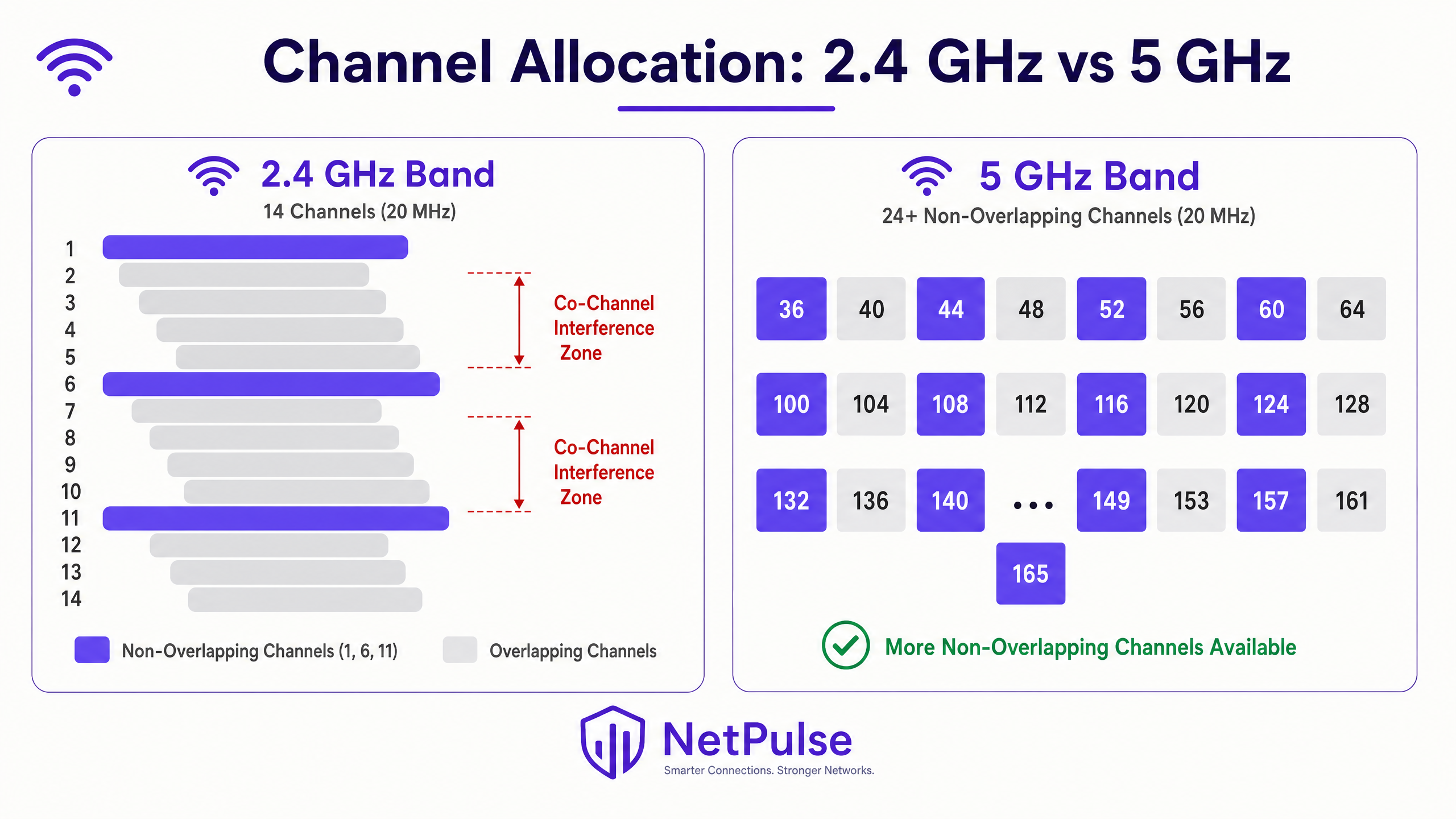
A banda de 2.4 GHz é notoriamente suscetível à CCI devido ao seu espectro limitado. Na maioria dos domínios regulatórios, existem apenas três canais não sobrepostos (1, 6 e 11) usando larguras de canal de 20 MHz. Em implementações de alta densidade — como pisos de lojas de retalho, alas de conferências de hotéis ou corredores de estádios — reutilizar estes três canais sem causar sobreposição é um desafio matemático que não pode ser resolvido apenas através do posicionamento dos APs.
A banda de 5 GHz oferece um alívio significativo, fornecendo 24 ou mais canais não sobrepostos de 20 MHz, dependendo das regulamentações regionais de Dynamic Frequency Selection (DFS). No entanto, a tentação de usar canais mais largos — 40 MHz, 80 MHz ou 160 MHz — para alcançar taxas de dados de pico mais altas frequentemente reintroduz a CCI. Com larguras de canal de 80 MHz, o número de canais não sobrepostos na banda de 5 GHz colapsa de 24 para aproximadamente seis. Para implementações empresariais, padronizar em canais de 20 MHz em 2.4 GHz e canais de 20 MHz ou 40 MHz em 5 GHz é uma melhor prática fundamental para maximizar a reutilização de canais e minimizar a interferência. Para mais contexto sobre o uso moderno do espectro, consulte Wi Fi Frequencies: A Guide to Wi-Fi Frequencies in 2026 .
A banda de 6 GHz introduzida pelo Wi-Fi 6E (IEEE 802.11ax) e Wi-Fi 7 (IEEE 802.11be) fornece mais 59 canais não sobrepostos de 20 MHz, representando uma oportunidade transformacional para implementações de alta densidade. No entanto, a adoção de 6 GHz requer atualizações de hardware tanto para APs quanto para clientes, tornando-o um investimento a médio prazo em vez de uma solução imediata para a infraestrutura existente.
Guia de Implementação
Passo 1: Realizar um Levantamento Abrangente do Local de RF
Antes de fazer quaisquer alterações de configuração, estabeleça uma linha de base. Um levantamento de local de RF ativo e passivo é crítico. Os levantamentos passivos capturam o ambiente de RF existente — força do sinal, piso de ruído, utilização do canal e fontes de interferência — sem se conectar à rede. Os levantamentos ativos medem o throughput real e o comportamento de roaming. Este não é um evento único; os ambientes mudam. Estruturas temporárias em locais de hotelaria, mudanças sazonais de inventário no retalho ou novos equipamentos em ambientes de saúde podem alterar significativamente a propagação de RF.
Ferramentas como Ekahau, NetSpot ou aplicações de levantamento específicas do fornecedor fornecem a visualização necessária para identificar zonas de interferência, lacunas de cobertura e conflitos de canal. O resultado de um levantamento de local deve informar diretamente o posicionamento dos APs, a atribuição de canais e as configurações de potência de transmissão.
Passo 2: Otimizar a Potência de Transmissão (Tx Power)
Uma conceção errada comum é que aumentar a potência de transmissão do AP melhora a cobertura e resolve problemas de conectividade. Na realidade, exacerba a CCI. Se o sinal de um AP alcançar mais longe do que o necessário, interfere com os vizinhosng células e cria um ambiente de RF assimétrico.
Corresponder às Capacidades do Cliente: Dispositivos móveis (smartphones, tablets) transmitem tipicamente a 10–15 dBm. Se um AP transmitir a 25 dBm, o cliente consegue ouvir o AP claramente, mas o AP tem dificuldade em ouvir o cliente — o clássico problema do nó oculto. Isto leva a retransmissões, débito efetivo reduzido e maior utilização do canal.
Diretrizes para Ajuste de Potência:
| Banda | Potência Tx Recomendada | Racional |
|---|---|---|
| 2.4 GHz | 10–14 dBm | Corresponder à capacidade Tx do smartphone; reduzir o tamanho da célula |
| 5 GHz | 14–17 dBm | Ligeiramente superior para compensar a perda de percurso em frequência mais alta |
| 6 GHz | 17–20 dBm | Maior perda de percurso requer um pouco mais de potência |
A potência de 2.4 GHz deve ser geralmente 3–6 dB inferior à de 5 GHz para encorajar o band steering, direcionando clientes capazes para a banda de 5 GHz menos congestionada.
Passo 3: Implementar Gestão Dinâmica de Rádio
Os controladores WLAN empresariais modernos apresentam algoritmos de gestão dinâmica de rádio — Radio Resource Management (RRM) da Cisco, Adaptive Radio Management (ARM) da Aruba, e equivalentes da Juniper Mist, Extreme Networks e outros. Estes sistemas monitorizam continuamente o ambiente de RF e ajustam dinamicamente as atribuições de canal e a potência de transmissão para mitigar a CCI.
No entanto, estes sistemas requerem um ajuste cuidadoso. Confiar inteiramente nas configurações automáticas predefinidas num ambiente de alta densidade, como um estádio ou um centro de transportes, leva frequentemente à instabilidade. Os principais parâmetros de ajuste incluem:
- Limiar de Mudança de Canal: O nível de interferência necessário para desencadear uma mudança de canal. Se for definido muito baixo, o sistema muda de canal constantemente em resposta a interferências transitórias (fornos de micro-ondas, dispositivos Bluetooth), causando desconexões de clientes.
- Intervalo de Mudança de Potência: Com que frequência o sistema ajusta a potência de transmissão. Em ambientes estáveis, ajustes menos frequentes reduzem a interrupção do cliente.
- Limites Mínimo e Máximo de Potência: Limites rígidos que impedem o algoritmo de definir níveis de potência fora dos seus parâmetros de design.
Passo 4: Desativar Taxas de Dados Básicas Legadas
Se o seu rádio de 2.4 GHz ainda tiver 1, 2, 5.5 e 11 Mbps ativados como taxas básicas (obrigatórias), os quadros de gestão — beacons, respostas de sonda e reconhecimentos — são transmitidos a estas taxas baixas. Um único beacon a 1 Mbps consome 10 vezes o tempo de antena do mesmo beacon a 11 Mbps. Em centenas de APs e milhares de clientes, esta sobrecarga é significativa.
Desativar taxas abaixo de 12 Mbps força todos os quadros de gestão e dados a usar modulação mais eficiente. Também encolhe efetivamente a célula de cobertura do AP, uma vez que apenas os clientes suficientemente próximos para atingir 12 Mbps ou mais podem associar-se. Isto cria um mecanismo natural para reduzir a pegada de CCI de cada AP.
Passo 5: Implementar 802.11k/v/r para Roaming Contínuo
Clientes "sticky" — dispositivos que se recusam a fazer roaming para um AP mais próximo — são um grande contribuinte para a CCI. Um cliente associado a um AP distante com uma taxa de dados baixa consome um tempo de antena desproporcionado, degradando o desempenho para todos os outros clientes nesse canal.
- 802.11k (Medição de Recursos de Rádio): Fornece aos clientes um relatório de vizinhança, informando-os sobre APs próximos e as suas forças de sinal.
- 802.11v (Gestão de Transição BSS): Permite que a rede envie sugestões de roaming aos clientes, pedindo-lhes efetivamente para se moverem para um AP melhor.
- 802.11r (Transição Rápida BSS): Reduz a latência do roaming através da pré-autenticação de clientes com APs de destino, crítico para aplicações de voz e vídeo.
Estes protocolos funcionam em conjunto para garantir que os clientes estão sempre associados ao AP ideal, reduzindo o consumo de tempo de antena por cliente e mitigando a CCI.
Melhores Práticas
Desativar Taxas de Dados Básicas Inferiores: Desativar as taxas de dados legadas (1, 2, 5.5 e 11 Mbps) força os clientes a usar esquemas de modulação mais eficientes. Isto reduz o tempo de antena necessário para os quadros de gestão e transmissão de dados, encolhendo efetivamente a célula de cobertura eficaz do AP. Esta é uma otimização fundamental para qualquer implementação empresarial moderna, conforme detalhado em Office Wi Fi: Optimize Your Modern Office Wi-Fi Network .
Aproveitar Canais DFS: Na banda de 5 GHz, utilize canais de Seleção Dinâmica de Frequência (DFS) (52–144 na maioria dos domínios regulatórios) para expandir o espectro não sobreposto disponível. Certifique-se de que os seus APs e dispositivos cliente suportam DFS, e monitorize eventos de radar que possam forçar mudanças de canal. Em ambientes onde os eventos de radar são frequentes (perto de aeroportos ou instalações militares), considere restringir-se a canais não-DFS.
Posicionamento Estratégico de AP: Evite colocar APs em corredores longos onde os sinais de RF se propagam sem impedimentos, criando o efeito de corredor. Em vez disso, coloque os APs dentro das salas ou áreas de cobertura específicas onde os utilizadores se reúnem. Use a estrutura física do edifício — paredes, pisos, estantes — como atenuadores de RF naturais para criar limites de célula.
Considerar BLE para Serviços de Localização: Se estiver a implementar serviços baseados em localização juntamente com WiFi, compreenda como o Bluetooth Low Energy interage com a sua infraestrutura sem fios. Consulte BLE Low Energy Explained for Enterprise para estratégias de integração detalhadas que evitam interferências entre beacons BLE e rádios WiFi.
Segmentar Tráfego de Convidados e Corporativo: Garanta que o tráfego Guest WiFi está devidamente segmentado da infraestrutura corporativa usando VLANs e SSIDs separados. Reduzir o número de SSIDs transmitidos por AP (idealmente não mais de três) reduz a sobrecarga dos quadros de gestão e melhora a eficiência geral do canal.
Resolução de Problemas e Mitigação de Riscos
O Problema do Cliente "Sticky"
Clientes que se recusam a fazer roaming para um AP mais próximo com um sinal mais forte contribuem significativamente para a CCI. À medida que um cliente "sticky" se afasta, a sua taxa de dados diminui,consumindo mais tempo de antena para transmitir a mesma quantidade de dados. Além de ativar o 802.11k/v, reveja a percentagem de sobreposição das suas células. As células devem sobrepor-se em aproximadamente 15–20% para um roaming contínuo. Uma maior sobreposição dá aos clientes menos incentivo para fazer roaming até que a qualidade do sinal já esteja severamente degradada.
Pontos de Acesso Maliciosos
APs não autorizados introduzidos por funcionários ou convidados — routers de consumo ligados a portas Ethernet — podem devastar um plano de canais cuidadosamente planeado. Implemente Sistemas de Prevenção de Intrusão Sem Fios (WIPS) contínuos para detetar e suprimir APs maliciosos. Garanta que a sua postura de controlo de acesso à rede é robusta e considere rever recursos sobre a modernização da sua infraestrutura NAC: La lista de verificación para migrar de NAC heredado a NAC nativo de la nube ou A Lista de Verificação para Migrar de NAC Legado para NAC Nativo da Nuvem .
Fontes de Interferência Não-WiFi
Nem toda a interferência provém de outros APs. Fornos de micro-ondas, dispositivos Bluetooth, monitores de bebé e telefones DECT operam todos na banda de 2.4 GHz. Analisadores de espectro podem identificar estas fontes de interferência não-802.11, que os algoritmos RRM podem interpretar erroneamente como interferência WiFi e responder de forma inadequada. Identificar e eliminar ou realocar estas fontes é frequentemente mais eficaz do que as mudanças de canal.
Modos de Falha Comuns
| Modo de Falha | Causa Raiz | Mitigação |
|---|---|---|
| Altas taxas de repetição (>10%) | CCI ou nó oculto | Reduzir potência Tx; rever plano de canais |
| Baixo débito apesar de sinal forte | Demasiados clientes por AP; CCI | Adicionar APs; reduzir largura de canal |
| Mudanças constantes de canal | Limiares RRM demasiado baixos | Aumentar limiar de interferência |
| Clientes sem roaming | Sem 802.11k/v; sobreposição excessiva de células | Ativar 802.11k/v; ajustar potência Tx |
| Quedas intermitentes em 5 GHz | Evento de radar DFS | Monitorizar eventos DFS; considerar canais não-DFS |
ROI e Impacto no Negócio
Resolver a CCI proporciona retornos mensuráveis e quantificáveis. Num ambiente de retalho, a conectividade fiável permite transações móveis de ponto de venda contínuas, consultas de inventário em tempo real e atualizações de sinalização digital. Uma única interrupção de POS durante o pico de vendas pode custar milhares de libras em vendas perdidas e perturbações operacionais. Na hotelaria, o desempenho da rede influencia diretamente as pontuações de avaliação dos hóspedes em plataformas como TripAdvisor e Google, com a conectividade a classificar-se consistentemente como um dos três principais fatores de satisfação dos hóspedes.
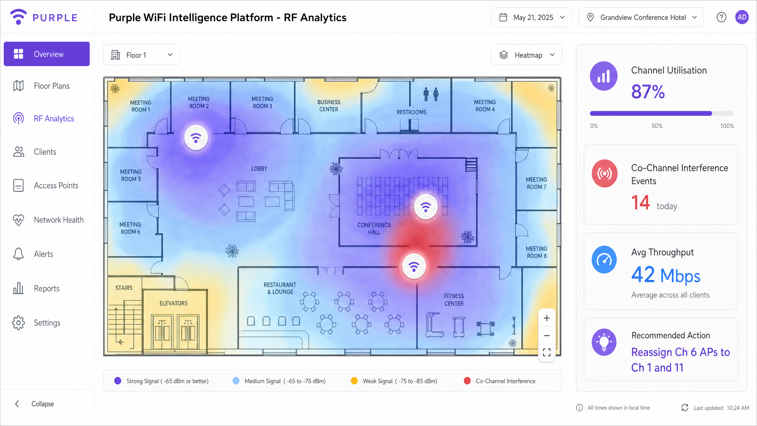
Ao aproveitar o WiFi Analytics para monitorizar continuamente a utilização do canal, o número de clientes por AP, as taxas de repetição e os eventos de interferência, as equipas de TI podem fazer a transição da resolução de problemas reativa para a gestão proativa da rede. Os principais indicadores de desempenho a monitorizar após a remediação incluem:
- Utilização do Canal: Objetivo abaixo de 50% para um desempenho fiável; acima de 70% indica um problema de capacidade.
- Taxa de Repetição: Objetivo abaixo de 5%; acima de 10% indica interferência significativa ou problemas de cobertura.
- Débito Médio do Cliente: Linha de base antes e depois das alterações para quantificar a melhoria.
- Volume de Tickets de Suporte: Os tickets relacionados com WiFi devem diminuir de forma mensurável dentro de 30 dias após a remediação.
O investimento num levantamento profissional do local de RF e na remediação do plano de canais geralmente compensa dentro de um a dois trimestres através da redução dos custos de suporte de TI e da melhoria da continuidade operacional.
Definições Principais
Co-Channel Interference (CCI)
Interference caused when multiple access points and clients operate on the same frequency channel, forcing them to share airtime via CSMA/CA and wait for the channel to clear before transmitting. CCI scales with the number of APs on the same channel.
The primary cause of degraded performance in dense deployments. Often misdiagnosed as an 'internet speed' or 'bandwidth' issue by end-users and non-technical stakeholders.
Adjacent-Channel Interference (ACI)
Interference caused by overlapping frequency bands — for example, using channels 1 and 3 simultaneously in the 2.4 GHz band. Unlike CCI, ACI is caused by spectral overlap rather than channel sharing.
Easily avoided by adhering strictly to non-overlapping channels (1, 6, 11 in 2.4 GHz). ACI is less common in well-managed enterprise networks but frequently seen in environments with rogue APs.
Carrier Sense Multiple Access with Collision Avoidance (CSMA/CA)
The protocol WiFi uses to manage access to the RF medium. Devices must listen for a clear channel before transmitting, and use random backoff timers to avoid simultaneous transmissions.
Understanding CSMA/CA is fundamental to understanding why CCI destroys throughput. It is a polite, orderly protocol that fails under heavy contention — the more devices sharing a channel, the longer each must wait.
Dynamic Frequency Selection (DFS)
A regulatory mechanism that allows WiFi devices to share spectrum with radar systems in the 5 GHz band. APs must monitor for radar signals and vacate the channel within 10 seconds if detected.
Crucial for enterprise deployments to unlock additional non-overlapping channels in the 5 GHz band. Requires careful monitoring; unexpected DFS events can cause client disconnects if not managed properly.
Hidden Node Problem
Occurs when two client devices can hear the AP but cannot hear each other, leading them to transmit simultaneously and cause collisions at the AP. Results in high retry rates and reduced throughput.
Often caused by APs transmitting at significantly higher power levels than client devices. Mitigated by matching AP Tx power to client Tx capability.
Radio Resource Management (RRM)
Automated systems within enterprise WLAN controllers that dynamically adjust channel assignments and transmit power based on continuous RF monitoring. Examples include Cisco RRM and Aruba ARM.
Useful in dynamic environments but requires careful threshold tuning. Default settings are rarely optimal for high-density venues and can cause instability if too aggressive.
Airtime Fairness
A WLAN feature that allocates equal transmission time to all associated clients, regardless of their data rate. Prevents slower (legacy or distant) clients from monopolising the channel at the expense of faster clients.
Critical in mixed-device environments (e.g., a hotel with both modern smartphones and legacy IoT sensors). Without airtime fairness, a single slow client can halve the effective throughput for all other clients on the channel.
BSS Transition Management (802.11v)
An IEEE 802.11 protocol that allows a WLAN controller to send roaming suggestions to client devices, recommending they associate with a different (closer or less congested) AP.
Part of the 802.11k/v/r suite of roaming protocols. Directly addresses the sticky client problem by giving the network a mechanism to influence client roaming decisions.
Channel Utilisation
The percentage of time a given RF channel is occupied by transmissions (both 802.11 and non-802.11). A key metric for diagnosing CCI.
Target below 50% for reliable performance. Above 70% indicates a capacity problem requiring channel plan remediation or additional AP density with reduced cell sizes.
Exemplos Práticos
A 400-room luxury hotel is experiencing severe connectivity issues in the conference centre during a major tech summit. 800 attendees report slow speeds and frequent disconnects despite dense AP placement. The IT team has already tried rebooting all APs.
Step 1: Conduct an immediate spectrum analysis using a laptop-based tool (Ekahau, Metageek Chanalyzer) to baseline channel utilisation and interference levels. The analysis reveals 2.4 GHz channel utilisation at 94% and significant CCI on 5 GHz due to 80 MHz channel widths across all APs.
Step 2: Disable 2.4 GHz radios on every other AP in the high-density conference area. With 800 devices in a confined space, the 2.4 GHz band is beyond saturation. Reducing the number of competing APs on three channels immediately reduces contention.
Step 3: Reduce 5 GHz channel widths from 80 MHz to 20 MHz across all conference centre APs. This increases available non-overlapping channels from approximately 6 to 24, allowing each AP to operate on a unique channel.
Step 4: Lower AP transmit power to 12 dBm (2.4 GHz) and 15 dBm (5 GHz) to shrink cell sizes and encourage clients to associate with the nearest AP rather than a distant one.
Step 5: Disable basic data rates below 12 Mbps on all radios.
Step 6: Validate with a post-change spectrum analysis. Channel utilisation should drop below 60% and retry rates below 8%.
A national retail chain has deployed APs down the centre of every aisle in a large warehouse-style store. Staff report poor roaming on handheld scanners and persistent connectivity drops near the loading bay.
Step 1: Conduct a passive RF survey to visualise coverage and identify the hallway effect. The survey confirms that APs at opposite ends of 60-metre aisles are on the same channel and interfering with each other.
Step 2: Relocate APs to a staggered deployment pattern, positioning them above the racking rather than in the aisle centre. This uses the metal racking as a natural RF attenuator, creating distinct coverage cells per aisle section.
Step 3: Implement directional antennas (downtilt patch antennas) on specific APs near the loading bay to focus RF energy downward and limit horizontal propagation into adjacent cells.
Step 4: Adjust RRM profiles to react less aggressively to transient interference from loading bay equipment (forklifts, metal doors).
Step 5: Enable 802.11k and 802.11v on the WLAN controller to assist handheld scanner roaming decisions.
Step 6: Validate roaming performance by walking the floor with a handheld scanner and monitoring association events in the WLAN controller.
Perguntas de Prática
Q1. You are designing the WiFi network for a new high-density university lecture hall with 500 seats. The architect insists on hiding all APs above a metal-mesh drop ceiling for aesthetic reasons. The university requires reliable 4K video streaming for remote lectures. How do you address the architectural constraint without compromising RF performance?
Dica: Consider the impact of metal mesh on RF propagation, the resulting requirement for Tx power, and the asymmetric coverage problem this creates.
Ver resposta modelo
The metal mesh will severely attenuate the RF signal, potentially by 10–20 dB depending on mesh density. To compensate, APs would need to transmit at maximum power, which increases CCI in adjacent spaces and creates a significant hidden node problem for clients trying to transmit back through the mesh. The recommended approach is to negotiate the use of APs with external directional antennas (downtilt patch antennas) mounted below the ceiling tile, with the AP body concealed above the mesh. Alternatively, specify aesthetically designed APs (e.g., Cisco Meraki or Aruba with low-profile enclosures) that can be mounted flush below the ceiling. If the architect is immovable on the metal mesh, specify APs with external antenna ports and route antenna cables through the mesh to below-ceiling mounting points. Under no circumstances should RF design be compromised for aesthetics when 4K streaming reliability is a stated requirement.
Q2. A retail client is upgrading their POS tablets to a new model that only supports 2.4 GHz WiFi. They currently operate a well-managed dual-band network with 30 APs in a medium-sized store. What changes should you make to accommodate the new tablets without degrading overall network performance for other devices?
Dica: Focus on band steering, basic data rates, and the impact of adding 2.4 GHz-only devices to an already constrained band.
Ver resposta modelo
First, ensure band steering is aggressively enabled to push all capable devices (smartphones, modern laptops) to the 5 GHz band, clearing airtime on 2.4 GHz for the POS tablets. Second, audit the 2.4 GHz channel plan to ensure strict adherence to channels 1, 6, and 11 with no deviations. Third, disable basic data rates below 12 Mbps on the 2.4 GHz band to force the POS tablets to transmit more efficiently, reducing their airtime consumption per transaction. Fourth, consider disabling 2.4 GHz radios on select APs if the density is too high — creating fewer, larger 2.4 GHz cells while maintaining dense 5 GHz coverage. Finally, monitor 2.4 GHz channel utilisation post-deployment and set an alert threshold at 60% to catch degradation before it impacts POS performance.
Q3. After deploying a new WLAN controller, the automated Radio Resource Management feature is constantly changing channels every 15–20 minutes, causing brief disconnects for VoIP users and complaints from the operations team. The IT manager wants to disable RRM entirely. What is your recommendation?
Dica: Consider the trade-off between RRM stability and the long-term benefit of automated channel management in a dynamic environment.
Ver resposta modelo
Disabling RRM entirely is not recommended. Without automated channel management, the network will gradually degrade as the RF environment changes (new equipment, seasonal changes, rogue APs). The correct approach is to tune the RRM thresholds rather than disable the feature. Increase the interference threshold required to trigger a channel change — the algorithm is currently reacting to transient interference that does not warrant a channel change. Extend the minimum time between channel changes to at least 60 minutes. Consider implementing a scheduled maintenance window for channel changes, restricting automated changes to off-peak hours (e.g., 02:00–04:00). Enable event logging for all RRM-triggered changes to identify the specific interference source causing the frequent triggers. Once the root cause is identified (often a non-WiFi interference source like a microwave or DECT phone), address it directly.