RSSI und Signalstärke verstehen für optimale Kanalplanung
Dieser Leitfaden bietet einen umfassenden technischen Einblick in RSSI, Signal-Rausch-Verhältnis (SNR) und RF-Ausbreitungsprinzipien für eine optimale Kanalplanung. Er stattet IT-Manager, Netzwerkarchitekten und Betriebsleiter von Veranstaltungsorten mit umsetzbaren Strategien aus, um Gleichkanal- und Nachbarkanalinterferenzen zu mindern, die AP-Platzierung zu optimieren und Analysen für messbare Geschäftsauswirkungen in den Bereichen Gastgewerbe, Einzelhandel und öffentlicher Sektor zu nutzen.
Diesen Leitfaden anhören
Podcast-Transkript ansehen
Zusammenfassung für Führungskräfte
Für CTOs und Netzwerkarchitekten, die Veranstaltungsorte mit hoher Dichte beaufsichtigen – sei es im Gastgewerbe , im Einzelhandel oder in großen öffentlichen Räumen – ist die Bereitstellung einer robusten drahtlosen Infrastruktur grundlegend für die betriebliche Effizienz und die Zufriedenheit der Gäste. Dieser technische Leitfaden untersucht, was RSSI ist und wie es als kritische Metrik für eine optimale Kanalplanung fungiert. Indem IT-Führungskräfte über grundlegende Abdeckungskarten hinausgehen und die Nuancen der RF-Ausbreitung, der Gleichkanalinterferenz (CCI) und der Nachbarkanalinterferenz (ACI) verstehen, können sie Netzwerke entwerfen, die Anwendungen mit hohem Durchsatz und geringer Latenz in großem Maßstab unterstützen. Wir untersuchen, wie präzise RSSI-Schwellenwerte Roaming-Entscheidungen steuern, wie die Kanalbreite die spektrale Effizienz beeinflusst und wie die Nutzung fortschrittlicher WiFi Analytics -Plattformen Risiken mindern und einen messbaren ROI liefern kann. Der Leitfaden behandelt die Roaming-Protokolle IEEE 802.11k/v/r, die SNR-Optimierung, die AP-Platzierungsstrategie und reale Einsatzszenarien aus dem Gastgewerbe und dem Einzelhandel.
Technischer Einblick
Was ist RSSI? Definition und Messung
Der Received Signal Strength Indicator (RSSI) ist eine relative Messung des Leistungspegels eines von einem Client-Gerät empfangenen RF-Signals. Gemessen in Dezibel relativ zu einem Milliwatt (dBm) wird RSSI als negativer Wert ausgedrückt – je näher an Null, desto stärker das Signal. Ein Wert von -30 dBm stellt ein außergewöhnlich starkes Signal dar (typischerweise nur innerhalb eines Meters vom AP erreichbar), während -90 dBm an der Grenze der Nutzbarkeit liegt. Die folgende Tabelle bietet eine praktische Referenz für RSSI-Schwellenwerte und ihre entsprechende Anwendbarkeit:
| RSSI (dBm) | Signalqualität | Geeignete Anwendungen |
|---|---|---|
| -30 bis -50 | Exzellent | Alle Anwendungen, einschließlich 4K streaming und hochdichte VoWiFi |
| -51 bis -65 | Gut | Daten mit hohem Durchsatz, VoWiFi, location analytics |
| -66 bis -70 | Fair | Standarddaten, web browsing, E-Mail |
| -71 bis -80 | Schlecht | Nur grundlegende Konnektivität; VoWiFi unzuverlässig |
| Unter -80 | Unbrauchbar | Häufige Verbindungsabbrüche; nicht für enterprise deployment geeignet |
RSSI vs. Signal-Rausch-Verhältnis (SNR)
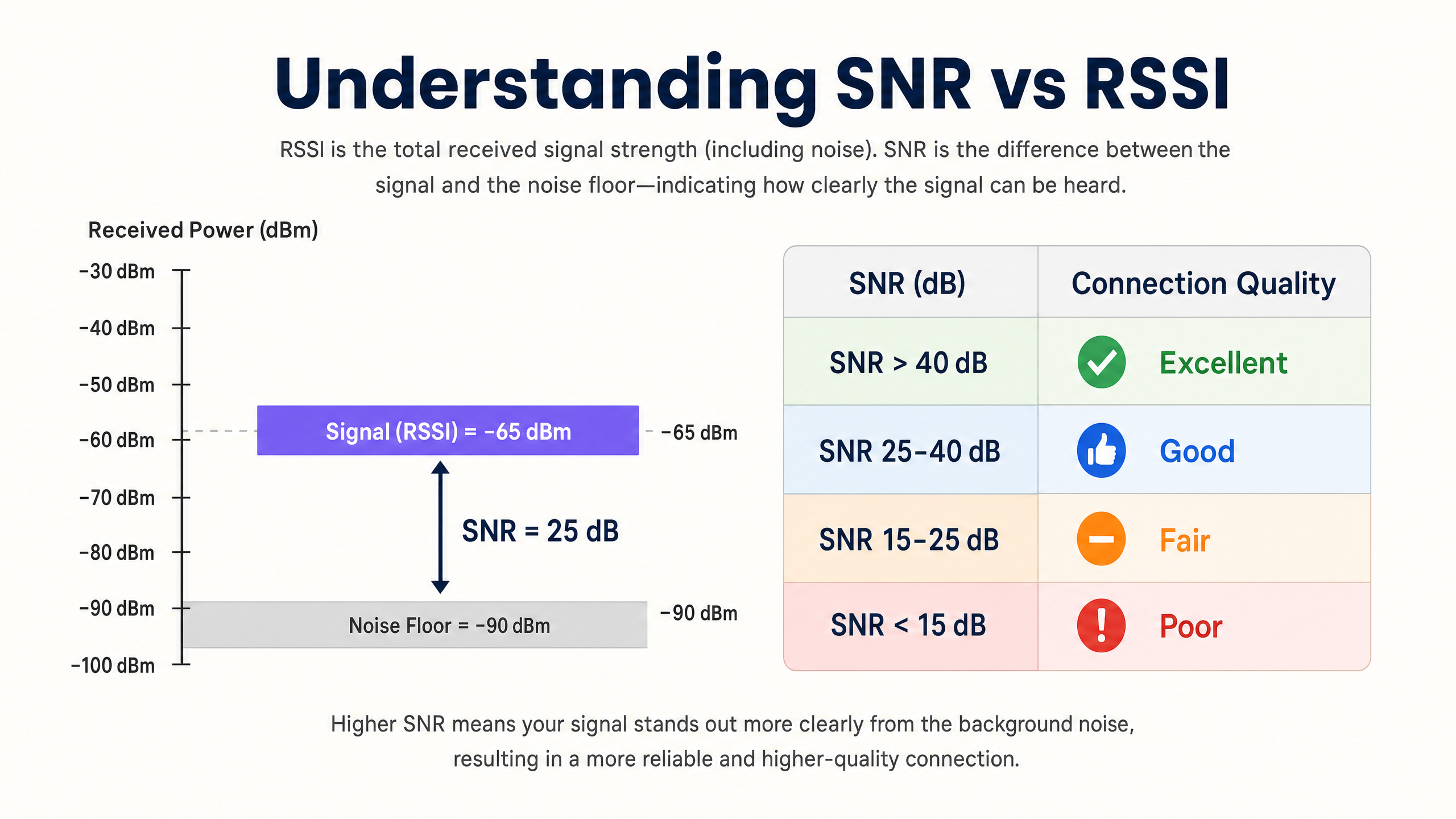
RSSI allein ist unzureichend, um die Netzwerkqualität zu bewerten. Das Signal-Rausch-Verhältnis (SNR) bietet ein genaueres Bild der Verbindungsqualität, indem es die empfangene Signalstärke mit dem Umgebungsrauschpegel vergleicht. Ein SNR von 25 dB oder höher ist typischerweise für Modulationsschemata mit hohem Durchsatz wie 256-QAM in 802.11ac/ax erforderlich. Wenn der Rauschpegel -90 dBm beträgt und der RSSI -65 dBm, beträgt das SNR 25 dB – der Mindestschwellenwert für einen zuverlässigen Hochleistungsbetrieb.
Die praktische Implikation ist signifikant: Ein Netzwerk kann auf einer Abdeckungs-Heatmap exzellente RSSI-Werte anzeigen, aber schlecht funktionieren, weil der Rauschpegel durch Nicht-Wi-Fi-Interferenzquellen (Mikrowellenherde, DECT-Telefone, Bluetooth-Geräte oder Industrieanlagen) erhöht ist. Instrumentieren Sie immer sowohl RSSI als auch SNR bei Standortbegehungen und der laufenden Überwachung.
Die Physik der RF-Ausbreitung und Dämpfung
In komplexen Umgebungen wie Krankenhäusern ( Healthcare ) oder Verkehrsknotenpunkten ( Transport ) erfahren RF-Signale eine Dämpfung, wenn sie physische Hindernisse durchdringen. Netzwerkarchitekten müssen diese materialspezifischen Verluste bei der Durchführung prädiktiver Standortbegehungen und der Definition von Zellgrenzen berücksichtigen:
| Material | Typische Dämpfung (dB) |
|---|---|
| Trockenbau / Gipskarton | 3–4 dB |
| Glas (Standard) | 2–3 dB |
| Ziegel | 8–12 dB |
| Beton | 12–15 dB |
| Stahlbeton / Stahl | 15–25+ dB |
| Metallregale (Einzelhandel) | 10–20 dB |
Die logarithmische Natur der Dezibelskala ist entscheidend zu verinnerlichen: Ein Verlust von 3 dB halbiert die Signalleistung, während ein Verlust von 10 dB sie um den Faktor zehn reduziert. Ein Signal, das zwei Ziegelwände durchdringt (ca. 20 dB Dämpfung), ist daher 100-mal schwächer als das gesendete Signal.
Kanalplanung: CCI und ACI
Eine optimale Kanalplanung erfordert die Minderung zweier unterschiedlicher Interferenztypen. Gleichkanalinterferenz (CCI) tritt auf, wenn Access Points, die auf demselben Kanal arbeiten, sich „hören“ können, was zu einer Medienkonkurrenz und erhöhter Latenz aufgrund des CSMA/CA (Carrier-Sense Multiple Access with Collision Avoidance)-Protokolls führt. Jedes Gerät auf dem Kanal muss warten, bis es an der Reihe ist, und wenn mehrere APs gleichzeitig konkurrieren, steigt die Kanalauslastung selbst bei moderater Client-Last stark an.
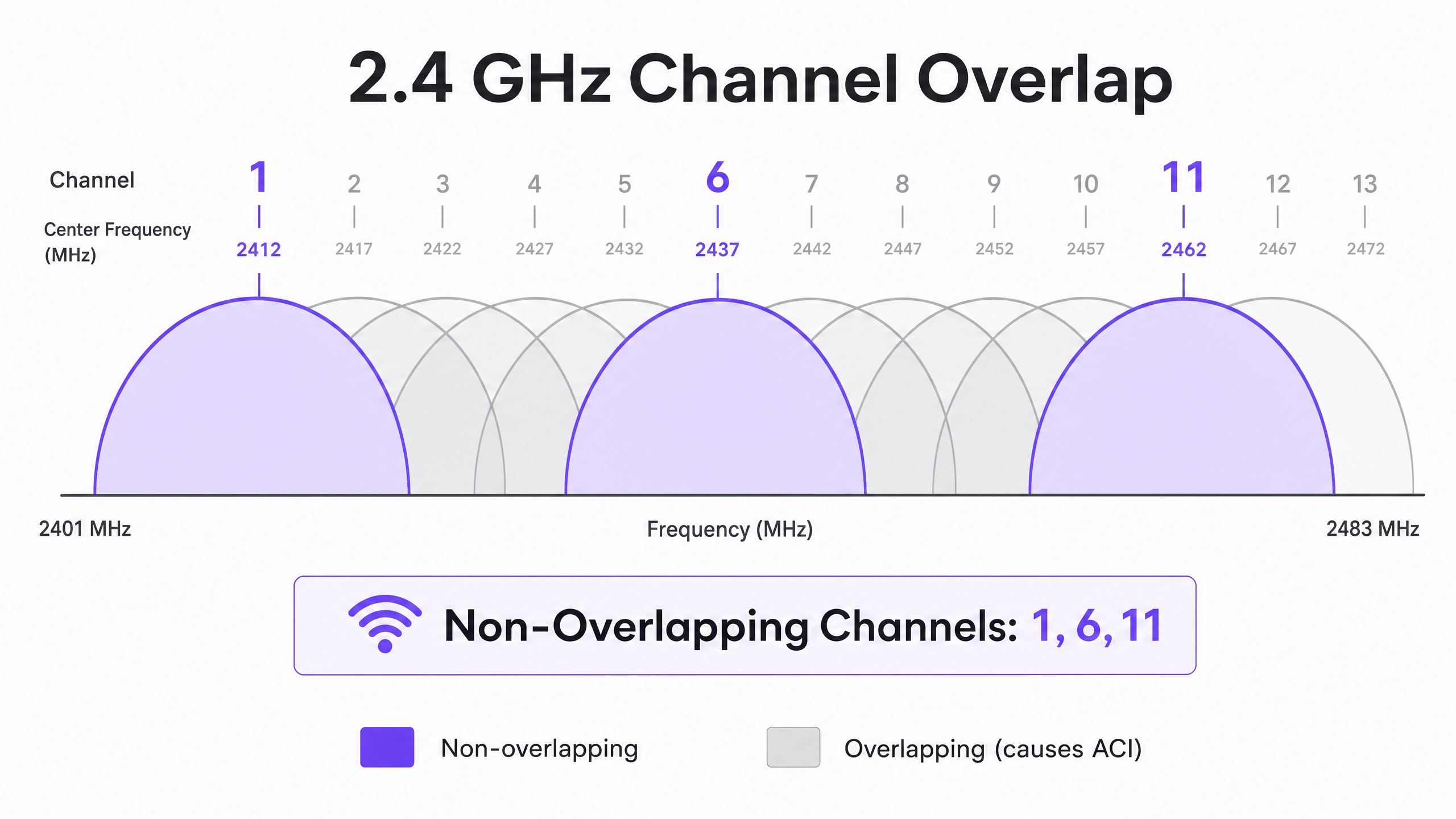
Nachbarkanalinterferenz (ACI) tritt auf, wenn APs auf überlappenden Kanälen arbeiten, was den Rauschpegel erhöht und das SNR verschlechtert. Im 2.4 GHz-Band sind nur die Kanäle 1, 6 und 11 nicht überlappend. Jede andere Kanalzuweisung verursacht ACI mit einem oder beiden Nachbarn. Im 5 GHz-Band erweitert die Nutzung von Dynamic Frequency Selection (DFS)-Kanälen das verfügbare Spektrum, obwohl Radardetektionsereignisse Kanalwechsel erzwingen können, was zu kurzen Konnektivitätsunterbrechungen führt.
Bei der Entscheidung über Kanalbreiten siehe 20MHz vs 40MHz vs 80MHz: Which Channel Width Should You Use? (oder die italienische Version: 20MHz vs 40MHz vs 80MHz: Quale larghezza di canale dovresti usare? ). Das Kernprinzip: Breitere Kanäle bieten einen höheren theoretischen Durchsatz, reduzieren jedoch die Anzahl der nicht überlappenden Optionen, was die CCI in dichten Umgebungen erhöht.
Implementierungsleitfaden
Schritt 1: Anforderungen definieren und das LCMI-Gerät identifizieren
Vor der Bereitstellung der Hardware definieren Sie den primären Abdeckungsbereich (Primary Coverage Area, PCA) und den sekundären Abdeckungsbereich (Secondary Coverage Area, SCA). Identifizieren Sie kritisch das Gerät mit der geringsten Leistungsfähigkeit, aber höchsten Wichtigkeit (LCMI) – das Gerät mit dem schwächsten Funkmodul, das unbedingt zuverlässig funktionieren muss. Dies ist häufig ein älterer Handscanner in einem Lager, ein spezifisches medizinisches Gerät in einem Krankenhaus oder ein älteres Smartphone in einer Hotelumgebung. Entwerfen Sie die gesamte RF-Architektur so, dass sie die minimalen RSSI-Anforderungen dieses Geräts erfüllt, und alles andere wird besser funktionieren.
Schritt 2: Durchführung einer aktiven Standortbegehung
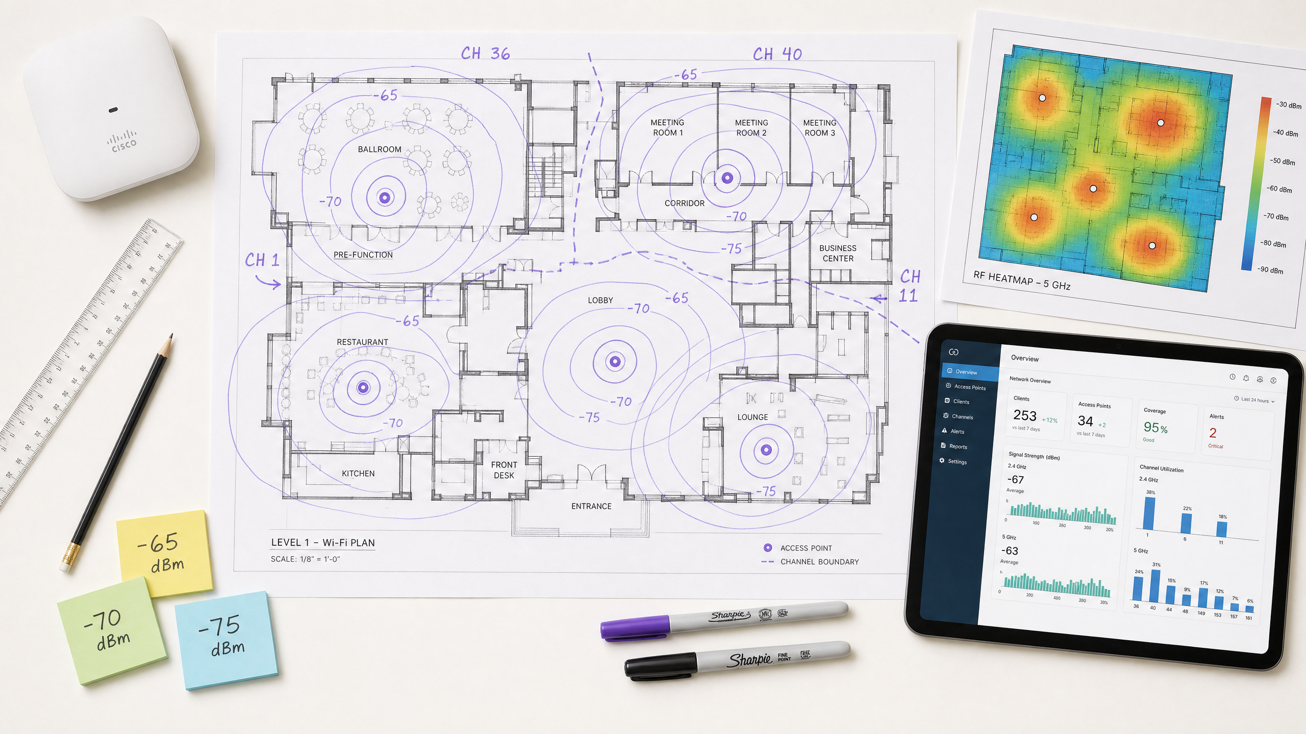
Führen Sie eine aktive Standortbegehung durch, um RSSI und SNR in der realen Welt zu messen – nicht nur eine prädiktive Umfrage mittels Software. Verwenden Sie Spektrumanalyse-Tools, um Nicht-Wi-Fi-Interferenzquellen zu identifizieren. Stellen Sie sicher, dass die primäre Abdeckung den Schwellenwert von -65 dBm und die sekundäre Abdeckung (für Roaming-Überlappungszonen) -70 dBm erfüllt. Dokumentieren Sie das Grundrauschen in allen Bereichen, da dies die erreichbare SNR und die maximal unterstützten Datenraten bestimmt.
Schritt 3: AP-Platzierung und Leistungsoptimierung
Vermeiden Sie den Irrglauben „lauter ist besser“. Eine zu hohe Sendeleistung des APs erzeugt asymmetrische Verbindungen, bei denen der Client den AP klar hören kann, der AP jedoch die schwächeren Übertragungen des Clients nicht zuverlässig empfangen kann. Dies ist die Ursache des Sticky Client-Problems – Geräte, die mit einem entfernten AP verbunden bleiben, obwohl sie sich physisch näher an einem anderen befinden. Passen Sie die Sendeleistung des APs auf 10–14 dBm an, um den Client-Fähigkeiten zu entsprechen, und stellen Sie eine Zellüberlappung von 15–20 % sicher, um nahtloses Roaming gemäß IEEE 802.11k/v/r zu ermöglichen.
Schritt 4: Mindestobligatorische Datenraten durchsetzen
Deaktivieren Sie ältere Datenraten (1, 2, 5,5 und 11 Mbps in 2,4 GHz; 6 und 9 Mbps in 5 GHz). Dies erhöht den minimalen RSSI-Schwellenwert, bei dem ein Client die Verbindung als akzeptabel betrachtet, erzwingt frühere Roaming-Entscheidungen und verhindert, dass Clients mit niedriger Rate unverhältnismäßig viel Sendezeit verbrauchen.
Schritt 5: Gast-WiFi und Analysen integrieren
Die Bereitstellung einer Unternehmens- Guest WiFi -Lösung erfordert eine nahtlose Authentifizierung, die das Benutzererlebnis nicht beeinträchtigt. Implementieren Sie 802.1X für Unternehmensgeräte und sichere Captive Portals für Gäste, mit WPA3, wo die Gerätekompatibilität dies zulässt. Moderne Ansätze wie How a wi fi assistant Enables Passwordless Access in 2026 reduzieren die Einarbeitungsreibung und gewährleisten gleichzeitig die Einhaltung der PCI DSS- und GDPR-Anforderungen. Die in diesem Leitfaden beschriebene RF-Architektur ist die Voraussetzung für zuverlässige Analysen und Standortdienste – wenn die RF schlecht konzipiert ist, sind die Daten ungenau.
Best Practices
Für Kapazität, nicht für Abdeckung entwerfen. In modernen Umgebungen mit hoher Dichte ist die Einschränkung fast nie die Signalreichweite – es ist die Sendezeitkonkurrenz. Setzen Sie mehr APs mit geringerer Sendeleistung ein, anstatt weniger APs mit hoher Leistung. Dies reduziert CCI, verbessert das SNR und erhöht die Anzahl der Clients, die gleichzeitig bedient werden können.
Kanalbreiten je nach Umgebung standardisieren. Standardmäßig 20 MHz in 2,4 GHz universell verwenden. In 5 GHz 20 MHz in Umgebungen mit sehr hoher Dichte (Stadien, Konferenzsäle) und 40 MHz in Umgebungen mit moderater Dichte (Hotels, Einzelhandel) verwenden. 80 MHz nur für Szenarien mit geringer Dichte und hohem Durchsatz reservieren.
Den Roaming-Protokoll-Stack implementieren. Aktivieren Sie 802.11k (Radio Resource Measurement), 802.11v (BSS Transition Management) und 802.11r (Fast BSS Transition) auf allen APs. Dies stellt sicher, dass Roaming-Entscheidungen durch RF-Bedingungen und nicht durch Client-Trägheit gesteuert werden, und reduziert die Re-Authentifizierungs-Latenz von Hunderten von Millisekunden auf unter 50 ms.
Automatisch zugewiesene Kanäle manuell validieren. Die meisten Anbieter von Enterprise-APs bieten automatisches Radio Resource Management (RRM) an. Obwohl als Basis nützlich, kann RRM in komplexen Umgebungen suboptimale Entscheidungen treffen. Überprüfen Sie den Kanalplan nach der Bereitstellung immer und überschreiben Sie ihn bei Bedarf.
Kontinuierlich überwachen, nicht nur bei der Bereitstellung. RF-Umgebungen ändern sich im Laufe der Zeit – neue Interferenzquellen treten auf, Belegungsmuster verschieben sich und Firmware-Updates ändern das Funkverhalten. Nutzen Sie eine WiFi Analytics -Plattform mit kontinuierlicher RF-Überwachung, um Verschlechterungen zu erkennen, bevor sie Benutzer beeinträchtigen.
Für umfassendere Strategien zur Nutzung der Netzwerkinfrastruktur für Geschäftsergebnisse siehe How To Improve Guest Satisfaction: The Ultimate Playbook .
Fehlerbehebung & Risikominderung
Das Sticky Client Problem
Symptom: Geräte bleiben mit einem entfernten AP mit schlechtem RSSI (-80 dBm) verbunden, obwohl sie sich physisch näher an einem anderen AP mit starkem Signal befinden.
Grundursache: Die Sendeleistung des APs ist zu hoch, wodurch eine asymmetrische Verbindung entsteht. Der Client hört den AP gut und initiiert kein Roaming. Alternativ sind die 802.11k/v-Protokolle deaktiviert, wodurch der Client keine Anleitung zu besseren verfügbaren APs erhält.
Abhilfe: Senken Sie die Sendeleistung des APs auf 10–12 dBm. Aktivieren Sie 802.11k/v/r. Legen Sie minimale obligatorische Datenraten fest, um Clients zum Roaming zu zwingen, wenn der RSSI unter den Mindestratenschwellenwert fällt.
Hohe Gleichkanalinterferenz
Symptom: Die Kanalauslastung liegt selbst bei moderater Client-Last konstant über 40–50 %, was zu erhöhter Latenz und schlechtem Durchsatz führt.
Grundursache: APs auf demselben Kanal sind zu nah beieinander platziert, oder die Kanalbreiten sind für die Bereitstellungsdichte zu groß.
Abhilfe: Reduzieren Sie die Kanalbreite auf 20 MHz. Überprüfen Sie den Kanalplan, um die physische Trennung zwischen APs auf demselben Kanal zu maximieren. In 2,4 GHz, erwägen Sie Deaktivierung des Radios auf jedem zweiten AP in sehr dichten Umgebungen.
Erhöhter Rauschpegel
Symptom: RSSI-Werte sehen auf Heatmaps akzeptabel aus, aber der Durchsatz ist gering und Verbindungen sind instabil.
Grundursache: Nicht-Wi-Fi-Interferenzquellen (Mikrowellenherde, DECT-Telefone, Industrieanlagen, Bluetooth) erhöhen den Rauschpegel und verschlechtern das SNR unter den für hochrangige Modulation erforderlichen Schwellenwert.
Abhilfe: Verwenden Sie einen Spektrumanalysator, um Interferenzquellen zu identifizieren und zu charakterisieren. Migrieren Sie betroffene Clients, wo möglich, auf 5 GHz, da die meisten Nicht-Wi-Fi-Interferenzen im 2,4 GHz-Bereich konzentriert sind. Wenn Interferenzquellen nicht eliminiert werden können, erhöhen Sie die AP-Dichte, um den RSSI zu verbessern und dadurch ein ausreichendes SNR trotz des erhöhten Rauschpegels aufrechtzuerhalten.
Da Netzwerke in kommunale und öffentliche Räume expandieren, wird strategische Planung immer wichtiger. Für Einblicke in Implementierungen im öffentlichen Sektor lesen Sie, wie Purple ernennt Iain Fox zum VP Growth – Public Sector, um digitale Inklusion und Smart City Innovation voranzutreiben .
ROI & Geschäftsauswirkungen
Die Optimierung von RSSI und Kanalplanung wirkt sich direkt auf das Geschäftsergebnis in mehreren Dimensionen aus. Die folgende Tabelle fasst die wichtigsten Geschäftsergebnisse zusammen, die mit einem gut konzipierten drahtlosen Netzwerk verbunden sind:
| Geschäftsergebnis | Mechanismus | Typische Auswirkung |
|---|---|---|
| Reduzierte IT-Supportkosten | Weniger Konnektivitätsbeschwerden; weniger Vor-Ort-Besuche | 20–40% Reduzierung der Wi-Fi-bezogenen Support-Tickets |
| Verbesserte Gästezufriedenheit | Zuverlässige Hochgeschwindigkeits-Konnektivität im gesamten Veranstaltungsort | Messbare Verbesserung der NPS- und Bewertungs-Scores |
| Präzise Standortanalysen | Ausreichende AP-Dichte und SNR für zuverlässige Trilateration | Standortgenauigkeit von unter 3 Metern für Besucherfrequenzanalysen |
| Erfassung von Erstanbieterdaten | Zuverlässige Captive Portal-Leistung | Höhere Abschlussraten beim Guest Wi-Fi Onboarding |
| Betriebliche Effizienz | Zuverlässige Konnektivität für Handheld-Geräte, POS-Systeme, IoT | Reduzierte Transaktionsfehler und Betriebsstillstandszeiten |
Für Veranstaltungsortbetreiber ist zuverlässiges Wi-Fi kein Kostenfaktor mehr, sondern ein Umsatztreiber. Durch die Sicherstellung einer konsistenten Signalstärke und eines hohen SNR können Veranstaltungsorte Captive Portals zuverlässig einsetzen, um Erstanbieterdaten zu erfassen, personalisierte Marketingkampagnen voranzutreiben und den Customer Lifetime Value zu erhöhen. Die Investition in ein ordnungsgemäßes RF-Design führt zu einem messbaren ROI durch betriebliche Effizienz, verbesserte digitale Interaktion und die Möglichkeit, fortschrittliche Analysen und Standortdienste mit Vertrauen einzusetzen.
Die hardwareunabhängige Plattform von Purple integriert sich in bestehende Infrastrukturen, um die Analyseschicht auf einer gut konzipierten RF-Grundlage bereitzustellen – und wandelt Signalstärkedaten in umsetzbare Business Intelligence in den Bereichen Gastgewerbe , Einzelhandel , Gesundheitswesen und Transport um.
Schlüsseldefinitionen
RSSI (Received Signal Strength Indicator)
A relative measurement of the power level of an RF signal received by a client device, expressed in negative dBm. The closer to zero, the stronger the signal.
Used to determine coverage boundaries, trigger roaming decisions, and assess basic signal availability. Not sufficient on its own to evaluate link quality.
SNR (Signal-to-Noise Ratio)
The difference in decibels (dB) between the received signal strength and the ambient noise floor. Calculated as: SNR (dB) = RSSI (dBm) − Noise Floor (dBm).
The primary determinant of achievable modulation scheme and data rate. An SNR of 25 dB is the minimum for 256-QAM (high-throughput) operation. Always measure alongside RSSI.
CCI (Co-Channel Interference)
Interference that occurs when multiple APs and clients operate on the same channel and can detect each other's transmissions, causing medium contention under the CSMA/CA protocol.
The most common cause of high channel utilisation and latency in enterprise deployments. Mitigated by proper channel planning, power tuning, and ensuring adequate physical separation between APs on the same channel.
ACI (Adjacent Channel Interference)
Interference caused by RF energy from one channel bleeding into an adjacent overlapping channel, raising the noise floor and degrading SNR.
Caused by using overlapping channels in the 2.4 GHz band (anything other than 1, 6, 11). Avoided by strict adherence to non-overlapping channel assignments.
DFS (Dynamic Frequency Selection)
A regulatory mechanism that allows Wi-Fi devices to share the 5 GHz spectrum with radar systems by monitoring for radar signals and vacating the channel if detected.
Expands the available 5 GHz channel set, but requires APs to change channels upon radar detection, causing a brief connectivity disruption. Must be accounted for in deployments near airports, military installations, or weather radar sites.
CSMA/CA (Carrier-Sense Multiple Access with Collision Avoidance)
The medium access protocol used by Wi-Fi, in which devices listen to the RF channel before transmitting and defer if the channel is busy.
The fundamental reason Wi-Fi is a half-duplex, shared medium. CCI forces multiple APs and clients to contend for the same channel, which is why channel planning is critical to performance.
Sticky Client
A client device that remains associated with an AP delivering a weak signal despite being physically closer to a different AP with a stronger signal.
Caused by asymmetric link budgets (AP transmit power too high) or absence of 802.11k/v roaming protocols. Results in poor throughput, high latency, and degraded user experience.
LCMI (Least Capable, Most Important) Device
The device in a deployment with the weakest radio capabilities that is nonetheless critical to business operations.
Used as the design baseline for RF architecture. Designing to meet the LCMI device's requirements ensures all other devices perform adequately.
802.11k/v/r
A suite of IEEE 802.11 amendments: 802.11k (Radio Resource Measurement), 802.11v (BSS Transition Management), and 802.11r (Fast BSS Transition).
Together, these protocols enable intelligent, low-latency client roaming. 802.11k provides neighbour reports, 802.11v enables network-directed roaming, and 802.11r reduces re-authentication time to under 50 ms.
Ausgearbeitete Beispiele
A 300-room hotel is experiencing poor Wi-Fi performance in guest rooms despite having an AP in every corridor. Guests report dropped connections and slow speeds, particularly in rooms furthest from the corridor APs. The existing APs are configured at maximum transmit power (23 dBm) on auto channel assignment.
The root cause is a combination of Co-Channel Interference (CCI) from corridor APs hearing each other down the long hallways, signal attenuation through guest room doors and walls, and the sticky client problem caused by excessively high transmit power. The recommended solution is to transition to an in-room AP deployment model using wall-plate APs (e.g., Cisco Catalyst 9105AXW or Aruba AP-303H). Configure each AP with a transmit power of 10–12 dBm. Disable 2.4 GHz on every other AP in the corridor to reduce CCI. Standardise on 20 MHz channels in 5 GHz with a manual channel plan assigning channels 36, 40, 44, 48, 52, 56, 60, 64 in a repeating pattern. Enable 802.11k/v/r on all APs. Set minimum mandatory data rates to 12 Mbps in 2.4 GHz and 24 Mbps in 5 GHz. Validate with a post-deployment active site survey targeting -65 dBm RSSI and 25 dB SNR in all guest rooms.
A large retail chain operating 50,000 sq ft stores wants to deploy Wi-Fi location analytics to track customer footfall and dwell time by department. Initial data from the existing network shows location accuracy of ±15 metres, which is insufficient for department-level analysis. The existing infrastructure has APs mounted at 6-metre intervals along the central spine of the store.
Location analytics based on RSSI trilateration require a minimum of three APs to hear a client device simultaneously, with each AP receiving a signal of -75 dBm or better. The current linear AP layout means that in the outer departments, clients are only within range of one or two APs, making accurate trilateration impossible. The solution requires a redesigned AP layout using a staggered grid pattern with APs at the perimeter and interior of each department zone, ensuring that any point on the floor is within -75 dBm range of at least three APs. Reduce AP transmit power to 10 dBm to tighten RF cells and improve the differential between AP readings (which is what drives location accuracy). Enable 802.11k/v to ensure devices don't stick to distant APs, which skews location data. Integrate the AP infrastructure with Purple's WiFi Analytics platform to process RSSI data into footfall heatmaps and dwell time reports by department.
Übungsfragen
Q1. You are designing a Wi-Fi network for a 40,000-seat stadium. The venue operator wants maximum throughput for concurrent video streaming and social media uploads during events. You are considering using 80 MHz channels in the 5 GHz band to maximise per-client throughput. Is this the recommended approach, and what channel plan would you implement instead?
Hinweis: Consider the number of non-overlapping 80 MHz channels available in the 5 GHz band versus 20 MHz channels, and the impact of Co-Channel Interference in an open, high-density environment.
Musterlösung anzeigen
No. Using 80 MHz channels in a stadium is strongly contraindicated. In the standard 5 GHz UNII-1/2/2e bands, there are only a handful of non-overlapping 80 MHz channels, meaning that with the AP density required for 40,000 concurrent users, severe CCI is inevitable. The correct approach is to use 20 MHz channels throughout, which provides up to 24 non-overlapping channels in 5 GHz (including DFS), maximising channel reuse. Directional sector antennas should be used to tightly control RF cell coverage, pointing down into seating sections rather than radiating omnidirectionally. AP density should be calculated based on a target of no more than 30–50 clients per AP radio, with transmit power tuned to match the coverage area of each sector.
Q2. A warehouse deployment uses handheld barcode scanners that frequently drop connections when operators move between aisles. The APs are configured at maximum transmit power (23 dBm) to ensure full coverage. The scanners run a legacy WMS application that requires sub-100ms latency. What is the likely cause and what steps would you take to resolve it?
Hinweis: Consider the transmit power capabilities of a small handheld scanner versus an enterprise AP, and the implications for the link budget in both directions.
Musterlösung anzeigen
The likely cause is the sticky client problem resulting from an asymmetric link budget. The APs are transmitting at 23 dBm, so the scanners hear them well across the entire warehouse and do not initiate a roam. However, the scanners' internal radios typically transmit at only 15–17 dBm, meaning the AP cannot reliably receive the scanner's transmissions when it is far away. The solution is to lower AP transmit power to 10–12 dBm to match the scanners' capabilities, ensuring that the coverage cells are appropriately sized and that scanners roam when they move out of range. Enable 802.11k/v/r to facilitate fast roaming. Set minimum mandatory data rates to 12 Mbps to force earlier roaming decisions. Validate with an active site survey using the actual scanner hardware to confirm -65 dBm RSSI and 25 dB SNR throughout all aisles.
Q3. During a site survey for a new hospital wing, you measure an RSSI of -58 dBm from the primary AP throughout the target area. However, the noise floor measured by a spectrum analyser is consistently -72 dBm due to legacy medical monitoring equipment operating in the 2.4 GHz band. The hospital requires reliable VoWiFi for clinical communications. Will this network support VoWiFi, and what actions would you recommend?
Hinweis: Calculate the SNR and evaluate it against the minimum requirement for VoWiFi. Consider which frequency band is affected and what mitigation options are available.
Musterlösung anzeigen
No, this network will not reliably support VoWiFi in its current state. The SNR is calculated as -58 dBm - (-72 dBm) = 14 dB. This falls below the minimum 20 dB SNR required for VoWiFi and well below the 25 dB target for high-quality voice. Despite the strong RSSI of -58 dBm, the elevated noise floor from the medical equipment degrades the link quality to an unacceptable level. Recommended actions: First, migrate VoWiFi traffic to the 5 GHz band, which is largely unaffected by the legacy 2.4 GHz medical equipment. Second, increase AP density in the affected areas to improve RSSI to -50 dBm or better, which would yield an SNR of 22 dB even with the elevated noise floor — marginally acceptable for VoWiFi. Third, engage the biomedical engineering team to assess whether the legacy equipment can be replaced or shielded. Fourth, implement QoS (WMM) with voice traffic prioritisation to protect VoWiFi traffic from competing with data traffic during periods of congestion.