Understanding RSSI and Signal Strength for Optimal Channel Planning
This guide provides a comprehensive technical deep-dive into RSSI, Signal-to-Noise Ratio (SNR), and RF propagation principles for optimal channel planning. It equips IT managers, network architects, and venue operations directors with actionable strategies to mitigate Co-Channel and Adjacent Channel Interference, optimise AP placement, and leverage analytics for measurable business impact across hospitality, retail, and public-sector environments.
Listen to this guide
View podcast transcript
执行摘要
对于管理高密度场所(无论是 酒店住宿 、 零售 还是大型公共空间)的 CTO 和网络架构师而言,部署稳健的无线基础设施是提高运营效率和宾客满意度的基石。本技术指南深入探讨了什么是 RSSI,以及它如何作为优化信道规划的关键指标发挥作用。通过超越基础的覆盖范围图,深入理解射频传播、同信道干扰 (CCI) 和相邻信道干扰 (ACI) 的细微差别,IT 领导者可以设计出支持大规模、高吞吐量、低延迟应用的网络。我们将研究精确的 RSSI 阈值如何驱动漫游决策、信道宽度如何影响频谱效率,以及如何利用先进的 WiFi Analytics 平台来降低风险并提供可衡量的投资回报率 (ROI)。本指南涵盖了 IEEE 802.11k/v/r 漫游协议、SNR 优化、AP 部署策略以及来自酒店和零售环境的真实部署案例。
技术深度剖析
什么是 RSSI?定义与测量
接收信号强度指示 (RSSI) 是客户端设备接收到的射频信号功率水平的相对测量值。RSSI 以毫瓦分贝 (dBm) 为单位,表示为负值——越接近于零,信号越强。-30 dBm 的值代表极强的信号(通常仅在距离 AP 一米范围内才能达到),而 -90 dBm 则处于可用性的临界值。下表提供了 RSSI 阈值及其相应应用适用性的实用参考:
| RSSI (dBm) | 信号质量 | 适用应用 |
|---|---|---|
| -30 至 -50 | 极佳 | 所有应用,包括 4K 串流和高密度 VoWiFi |
| -51 至 -65 | 良好 | 高吞吐量数据、VoWiFi、位置分析 |
| -66 至 -70 | 尚可 | 标准数据、网页浏览、电子邮件 |
| -71 至 -80 | 较差 | 仅限基础连接;VoWiFi 不稳定 |
| 低于 -80 | 不可用 | 频繁断连;不适合企业级部署 |
RSSI 与信噪比 (SNR)
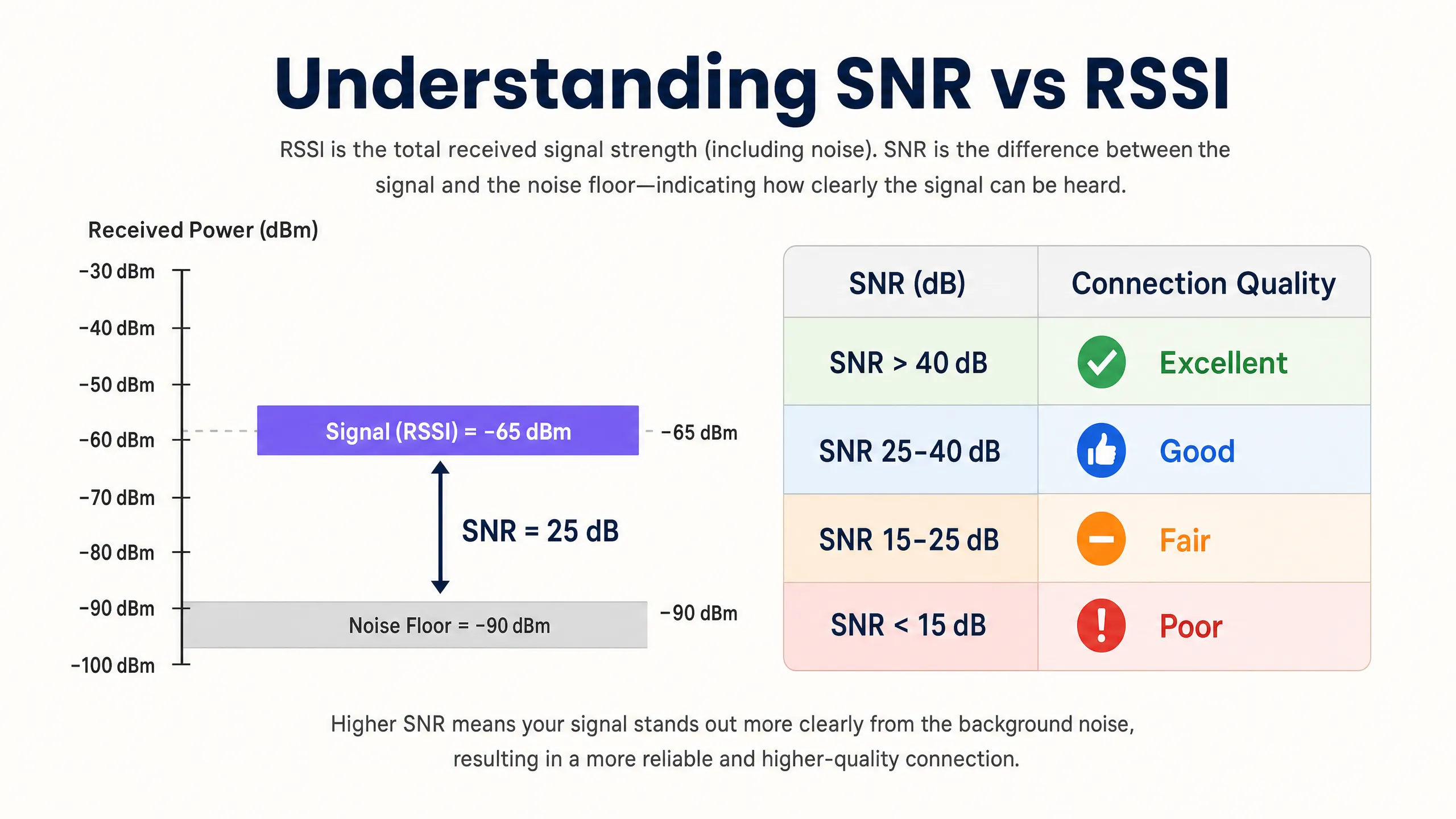
仅凭 RSSI 不足以评估网络质量。信噪比 (SNR) 通过对比接收信号强度与环境底噪,能够更准确地反映链路质量。通常需要 25 dB 或更高的 SNR 才能支持 802.11ac/ax 中 256-QAM 等高吞吐量调制方案。如果底噪为 -90 dBm 且 RSSI 为 -65 dBm,则 SNR 为 25 dB — 此时达到了可靠高性能运行的最低门槛。
在实际应用中,这意味着:网络可能在覆盖热图上显示出极佳的 RSSI 值,但由于非 Wi-Fi 干扰源(微波炉、DECT 电话、蓝牙设备或工业设备)抬高了底噪,导致性能表现糟糕。因此,在进行站点勘测和持续监控时,务必同时测量 RSSI 和 SNR。
射频传播与衰减的物理学原理
在医院( Healthcare )或交通枢纽( Transport )等复杂环境中,射频信号穿过物理障碍物时会发生衰减。网络架构师在进行预测性站点勘测和定义信噪比边界时,必须考虑到这些特定材料带来的损耗:
| 材质 | 典型衰减 (dB) |
|---|---|
| 石膏板 / 灰泥板 | 3–4 dB |
| 玻璃(标准) | 2–3 dB |
| 砖墙 | 8–12 dB |
| 混凝土 | 12–15 dB |
| 钢筋混凝土 / 钢材 | 15–25+ dB |
| 金属货架(零售) | 10–20 dB |
深入理解分贝标度的对数特性至关重要:3 dB 的损耗会使信号功率减半,而 10 dB 的损耗则会将信号功率降低十倍。因此,穿过两面砖墙的信号(约 20 dB 衰减)比发射信号弱 100 倍。
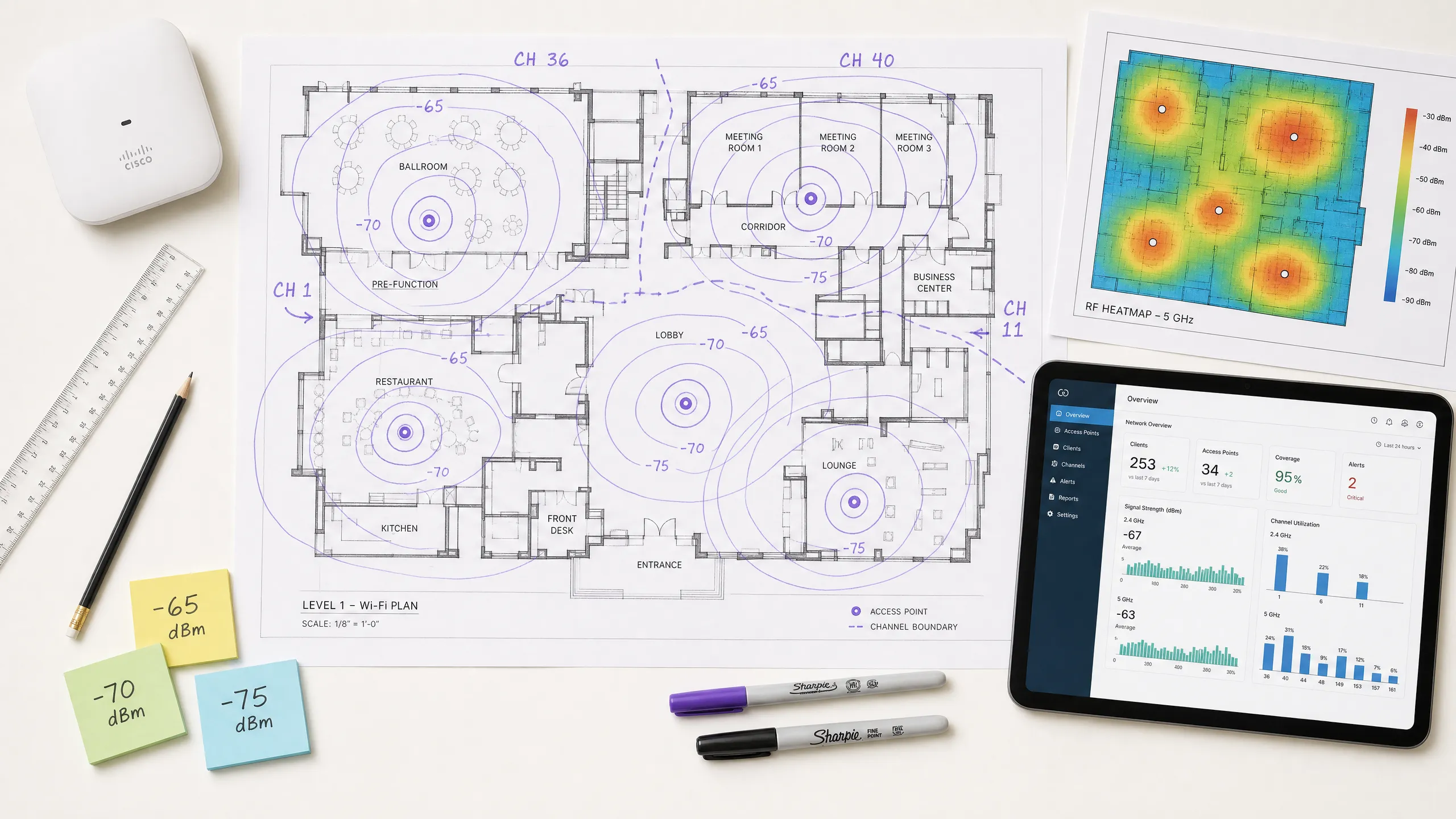
信道规划:同频干扰 (CCI) 与邻频干扰 (ACI)
最佳的信道规划需要减轻两种不同类型的干扰。当工作在同一信道上的接入点能够相互“听到”时,就会发生同频干扰 (CCI),由于 CSMA/CA(带有冲突避免的载波监听多路访问)协议,这会导致介质争用和延迟增加。该信道上的每个设备都必须轮流等待,当多个 AP 同时进行争用时,即使在温和的客户端负载下,信道利用率也会飙升。
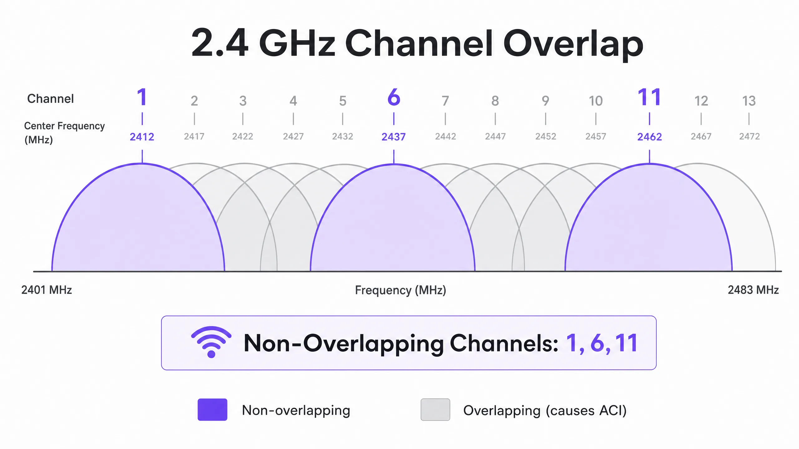
当 AP 工作在重叠信道上时,就会发生邻频干扰 (ACI),从而抬高底噪并降低 SNR。在 2.4 GHz 频段中,只有信道 1、6 和 11 是互不重叠的。任何其他信道分配都会对其一个或两个相邻信道造成 ACI。在 5 GHz 频段中,利用动态频率选择 (DFS) 信道可以扩展可用频谱,但雷达探测事件可能会强制更改信道,从而导致短暂的连接中断。 在确定信道宽度时,请参考 20MHz vs 40MHz vs 80MHz:您应该使用哪种信道宽度? (或意大利语版本: 20MHz vs 40MHz vs 80MHz: Quale larghezza di canale dovresti usare? )。核心原则:更宽的信道可以提供更高的理论吞吐量,但会减少非重叠信道的选择数量,从而在密集部署中增加同频干扰(CCI)。
实施指南
步骤 1:定义需求并识别 LCMI 设备
在部署硬件之前,请先定义主覆盖区域(PCA)和次覆盖区域(SCA)。至关重要的一点是,识别性能最弱但最重要的设备(LCMI)——即射频信号最弱且必须确保可靠运行的设备。这通常是仓库中的老旧手持扫描枪、医院中的特定型号医疗设备,或者是酒店环境中的旧款智能手机。在设计整个射频(RF)架构时,需确保其满足该设备的最低 RSSI 要求,这样其他所有设备的性能自然会更好。
步骤 2:进行主动站点勘测
进行主动站点勘测以测量实际的 RSSI 和 SNR——而不仅仅是使用软件进行预测性勘测。使用频谱分析工具来识别非 Wi-Fi 干扰源。确保主覆盖满足 -65 dBm 的阈值,次覆盖(用于漫游重叠区域)满足 -70 dBm。记录所有区域的底噪,因为这将决定可实现的 SNR 和支持的最大数据速率。
步骤 3:AP 部署与功率调整
避免 "信号越强越好" 的误区。将 AP 的发送功率设置得过高会导致非对称链路,即客户端可以清晰地接收到 AP 的信号,但 AP 却无法可靠地接收到客户端发出的较弱传输。这是**粘性客户端(sticky client)**问题的根本原因——即设备即使在物理距离上更靠近另一个 AP,却依然保持与较远 AP 的连接。将 AP 的发送功率调整至 10–14 dBm 以匹配客户端的能力,并确保 15–20% 的蜂窝重叠度,以促进符合 IEEE 802.11k/v/r 标准的无缝漫游。
步骤 4:强制执行最低强制数据速率
禁用传统数据速率(2.4 GHz 中的 1, 2, 5.5 和 11 Mbps;5 GHz 中的 6 和 9 Mbps)。这会提高客户端判定连接可接受的最低 RSSI 阈值,从而强制设备更早做出漫游决策,并防止低速率客户端占用过多的空口时间(airtime)。
步骤 5:集成访客 WiFi 与分析
部署企业级 Guest WiFi 解决方案需要无缝认证,且不能降低用户体验。为企业设备实施 802.1X,并为访客部署安全的 Captive Portal,在设备兼容性允许的情况下采用 WPA3。现代方法(例如 How a wi fi assistant Enables Passwordless Access in 2026 )可减少入网摩擦,同时保持符合 PCI DSS 和 GDPR 要求。本指南中描述的射频 (RF) 架构是可靠分析和定位服务的先决条件——如果射频设计不良,数据将会不准确。
最佳实践
针对容量而非覆盖范围进行设计。 在现代高密度环境中,限制因素几乎从来不是信号覆盖范围,而是信道空口争用。部署更多低发射功率的 AP,而不是部署少数高功率的 AP。这可以减少同信道干扰 (CCI),提高信噪比 (SNR),并增加可同时提供服务的客户端数量。
按环境标准化信道宽度。 在 2.4 GHz 频段中普遍默认使用 20 MHz。在 5 GHz 频段中,在极高密度环境(体育场、会议厅)中使用 20 MHz,在中等密度环境(酒店、零售)中使用 40 MHz。仅在低密度、高吞吐量场景下保留 80 MHz。
实现漫游协议栈。 在所有 AP 上启用 802.11k(无线资源测量)、802.11v(BSS 转型管理)和 802.11r(快速 BSS 转型)。这确保了漫游决策是由射频状况而非客户端惯性驱动,并将重新认证延迟从数百毫秒降低到 50 毫秒以下。
手动验证自动分配的信道。 大多数企业级 AP 厂商都提供自动无线资源管理 (RRM)。虽然 RRM 可以作为基准,但在复杂环境中可能会做出次优决策。务必在部署后审核信道规划,并在必要时进行覆盖。
持续监控,而不仅仅是在部署时。 射频环境会随着时间推移而变化——会出现新的干扰源,占用模式会发生变化,固件更新也会改变无线电行为。利用具有持续射频监控功能的 WiFi Analytics 平台,在影响用户之前检测到性能下降。
有关利用网络基础设施实现业务成果的更广泛策略,请参阅 How To Improve Guest Satisfaction: The Ultimate Playbook 。
故障排除与风险缓解
粘性客户端问题
症状: 设备仍连接到 RSSI 较差 (-80 dBm) 的远处 AP,尽管其物理位置更接近另一个信号强劲的 AP。
根本原因: AP 发射功率过高,导致链路不对称。客户端可以很好地接收到 AP 信号,因此不会发起漫游。或者,802.11k/v 协议已被禁用,导致客户端无法获得有关更好可用 AP 的引导。
**缓解措施:**将 AP 发射功率降低至 10–12 dBm。启用 802.11k/v/r。设置最低强制数据速率,以便在 RSSI 降至最低速率阈值以下时强制客户端进行漫游。
高同频干扰
**症状:**即使在温和的客户端负载下,信道利用率也持续高于 40–50%,导致延迟增加和吞吐量下降。
**根本原因:**相同信道上的 AP 部署距离过近,或者信道宽度对于部署密度而言过宽。
**缓解措施:**将信道宽度减少至 20 MHz。审查信道规划,以最大程度地增加相同信道上 AP 之间的物理间距。在极高密度的部署中,考虑在 2.4 GHz 频段下每隔一个 AP 禁用射频。
底噪升高
**症状:**热图上的 RSSI 值看起来尚可,但吞吐量较差且连接不稳定。
**根本原因:**非 Wi-Fi 干扰源(微波炉、DECT 电话、工业设备、蓝牙)抬高了底噪,使信噪比(SNR)降至高阶调制所需的阈值以下。
**缓解措施:**使用频谱分析仪来识别和确定干扰源的特征。尽可能将受影响的客户端迁移到 5 GHz,因为大多数非 Wi-Fi 干扰都集中在 2.4 GHz。如果干扰源无法消除,请增加 AP 密度以改善 RSSI,从而在底噪升高的情况下仍能保持足够的信噪比。
随着网络向市政和公共空间扩展,战略规划变得越来越关键。如需了解公共部门部署的洞察,请阅读 Purple 任命 Iain Fox 为公共部门增长副总裁以推动数字包容与智慧城市创新 。
投资回报率(ROI)与业务影响
优化 RSSI 和信道规划可在多个维度上直接影响企业收益。下表总结了与架构良好的无线网络相关的关键业务成果:
| 业务成果 | 作用机制 | 典型影响 |
|---|---|---|
| 降低 IT 支持成本 | 减少连接投诉;减少现场走访 | 与 Wi-Fi 相关的支持工单减少 20–40% |
| 提高访客满意度 | 在整个场所内提供可靠、高速的连接 | NPS(净推荐值)和评分显著提升 |
| 精准的定位分析 | 足够的 AP 密度和信噪比以实现可靠的三边测量 | 客流量分析的定位精度达到 3 米以内 |
| 第一方数据获取 | 可靠的 Captive Portal 性能 | 访客 Wi-Fi 接入的完成率更高 |
| 运营效率 | 为手持设备、POS 系统、IoT 提供可靠的连接 | 减少交易失败和运营停机时间 |
对于场所运营商而言,可靠的 Wi-Fi 不再是成本中心,而是收入增长的助推器。通过确保稳定的信号强度和高 SNR,场所可以信心十足地部署 Captive Portals 以获取第一方数据,从而推动个性化营销活动并提升客户终身价值。在合理的 RF 设计上进行投资,可通过提高运营效率、增强数字化互动以及信心十足地部署先进分析和定位服务,带来可衡量的 ROI。
Purple 的硬件兼容平台可与现有基础设施无缝集成,在设计良好的 RF 基础之上提供分析层——在 酒店 、 零售 、 医疗 和 交通 环境中,将信号强度数据转化为可落地的商业智能。
Key Definitions
RSSI (Received Signal Strength Indicator)
A relative measurement of the power level of an RF signal received by a client device, expressed in negative dBm. The closer to zero, the stronger the signal.
Used to determine coverage boundaries, trigger roaming decisions, and assess basic signal availability. Not sufficient on its own to evaluate link quality.
SNR (Signal-to-Noise Ratio)
The difference in decibels (dB) between the received signal strength and the ambient noise floor. Calculated as: SNR (dB) = RSSI (dBm) − Noise Floor (dBm).
The primary determinant of achievable modulation scheme and data rate. An SNR of 25 dB is the minimum for 256-QAM (high-throughput) operation. Always measure alongside RSSI.
CCI (Co-Channel Interference)
Interference that occurs when multiple APs and clients operate on the same channel and can detect each other's transmissions, causing medium contention under the CSMA/CA protocol.
The most common cause of high channel utilisation and latency in enterprise deployments. Mitigated by proper channel planning, power tuning, and ensuring adequate physical separation between APs on the same channel.
ACI (Adjacent Channel Interference)
Interference caused by RF energy from one channel bleeding into an adjacent overlapping channel, raising the noise floor and degrading SNR.
Caused by using overlapping channels in the 2.4 GHz band (anything other than 1, 6, 11). Avoided by strict adherence to non-overlapping channel assignments.
DFS (Dynamic Frequency Selection)
A regulatory mechanism that allows Wi-Fi devices to share the 5 GHz spectrum with radar systems by monitoring for radar signals and vacating the channel if detected.
Expands the available 5 GHz channel set, but requires APs to change channels upon radar detection, causing a brief connectivity disruption. Must be accounted for in deployments near airports, military installations, or weather radar sites.
CSMA/CA (Carrier-Sense Multiple Access with Collision Avoidance)
The medium access protocol used by Wi-Fi, in which devices listen to the RF channel before transmitting and defer if the channel is busy.
The fundamental reason Wi-Fi is a half-duplex, shared medium. CCI forces multiple APs and clients to contend for the same channel, which is why channel planning is critical to performance.
Sticky Client
A client device that remains associated with an AP delivering a weak signal despite being physically closer to a different AP with a stronger signal.
Caused by asymmetric link budgets (AP transmit power too high) or absence of 802.11k/v roaming protocols. Results in poor throughput, high latency, and degraded user experience.
LCMI (Least Capable, Most Important) Device
The device in a deployment with the weakest radio capabilities that is nonetheless critical to business operations.
Used as the design baseline for RF architecture. Designing to meet the LCMI device's requirements ensures all other devices perform adequately.
802.11k/v/r
A suite of IEEE 802.11 amendments: 802.11k (Radio Resource Measurement), 802.11v (BSS Transition Management), and 802.11r (Fast BSS Transition).
Together, these protocols enable intelligent, low-latency client roaming. 802.11k provides neighbour reports, 802.11v enables network-directed roaming, and 802.11r reduces re-authentication time to under 50 ms.
Worked Examples
A 300-room hotel is experiencing poor Wi-Fi performance in guest rooms despite having an AP in every corridor. Guests report dropped connections and slow speeds, particularly in rooms furthest from the corridor APs. The existing APs are configured at maximum transmit power (23 dBm) on auto channel assignment.
The root cause is a combination of Co-Channel Interference (CCI) from corridor APs hearing each other down the long hallways, signal attenuation through guest room doors and walls, and the sticky client problem caused by excessively high transmit power. The recommended solution is to transition to an in-room AP deployment model using wall-plate APs (e.g., Cisco Catalyst 9105AXW or Aruba AP-303H). Configure each AP with a transmit power of 10–12 dBm. Disable 2.4 GHz on every other AP in the corridor to reduce CCI. Standardise on 20 MHz channels in 5 GHz with a manual channel plan assigning channels 36, 40, 44, 48, 52, 56, 60, 64 in a repeating pattern. Enable 802.11k/v/r on all APs. Set minimum mandatory data rates to 12 Mbps in 2.4 GHz and 24 Mbps in 5 GHz. Validate with a post-deployment active site survey targeting -65 dBm RSSI and 25 dB SNR in all guest rooms.
A large retail chain operating 50,000 sq ft stores wants to deploy Wi-Fi location analytics to track customer footfall and dwell time by department. Initial data from the existing network shows location accuracy of ±15 metres, which is insufficient for department-level analysis. The existing infrastructure has APs mounted at 6-metre intervals along the central spine of the store.
Location analytics based on RSSI trilateration require a minimum of three APs to hear a client device simultaneously, with each AP receiving a signal of -75 dBm or better. The current linear AP layout means that in the outer departments, clients are only within range of one or two APs, making accurate trilateration impossible. The solution requires a redesigned AP layout using a staggered grid pattern with APs at the perimeter and interior of each department zone, ensuring that any point on the shop floor is within -75 dBm range of at least three APs. Reduce AP transmit power to 10 dBm to tighten RF cells and improve the differential between AP readings (which is what drives location accuracy). Enable 802.11k/v to ensure devices don't stick to distant APs, which skews location data. Integrate the AP infrastructure with Purple's WiFi Analytics platform to process RSSI data into footfall heatmaps and dwell time reports by department.
Practice Questions
Q1. You are designing a Wi-Fi network for a 40,000-seat stadium. The venue operator wants maximum throughput for concurrent video streaming and social media uploads during events. You are considering using 80 MHz channels in the 5 GHz band to maximise per-client throughput. Is this the recommended approach, and what channel plan would you implement instead?
Hint: Consider the number of non-overlapping 80 MHz channels available in the 5 GHz band versus 20 MHz channels, and the impact of Co-Channel Interference in an open, high-density environment.
View model answer
No. Using 80 MHz channels in a stadium is strongly contraindicated. In the standard 5 GHz UNII-1/2/2e bands, there are only a handful of non-overlapping 80 MHz channels, meaning that with the AP density required for 40,000 concurrent users, severe CCI is inevitable. The correct approach is to use 20 MHz channels throughout, which provides up to 24 non-overlapping channels in 5 GHz (including DFS), maximising channel reuse. Directional sector antennas should be used to tightly control RF cell coverage, pointing down into seating sections rather than radiating omnidirectionally. AP density should be calculated based on a target of no more than 30–50 clients per AP radio, with transmit power tuned to match the coverage area of each sector.
Q2. A warehouse deployment uses handheld barcode scanners that frequently drop connections when operators move between aisles. The APs are configured at maximum transmit power (23 dBm) to ensure full coverage. The scanners run a legacy WMS application that requires sub-100ms latency. What is the likely cause and what steps would you take to resolve it?
Hint: Consider the transmit power capabilities of a small handheld scanner versus an enterprise AP, and the implications for the link budget in both directions.
View model answer
The likely cause is the sticky client problem resulting from an asymmetric link budget. The APs are transmitting at 23 dBm, so the scanners hear them well across the entire warehouse and do not initiate a roam. However, the scanners' internal radios typically transmit at only 15–17 dBm, meaning the AP cannot reliably receive the scanner's transmissions when it is far away. The solution is to lower AP transmit power to 10–12 dBm to match the scanners' capabilities, ensuring that the coverage cells are appropriately sized and that scanners roam when they move out of range. Enable 802.11k/v/r to facilitate fast roaming. Set minimum mandatory data rates to 12 Mbps to force earlier roaming decisions. Validate with an active site survey using the actual scanner hardware to confirm -65 dBm RSSI and 25 dB SNR throughout all aisles.
Q3. During a site survey for a new hospital wing, you measure an RSSI of -58 dBm from the primary AP throughout the target area. However, the noise floor measured by a spectrum analyser is consistently -72 dBm due to legacy medical monitoring equipment operating in the 2.4 GHz band. The hospital requires reliable VoWiFi for clinical communications. Will this network support VoWiFi, and what actions would you recommend?
Hint: Calculate the SNR and evaluate it against the minimum requirement for VoWiFi. Consider which frequency band is affected and what mitigation options are available.
View model answer
No, this network will not reliably support VoWiFi in its current state. The SNR is calculated as -58 dBm - (-72 dBm) = 14 dB. This falls below the minimum 20 dB SNR required for VoWiFi and well below the 25 dB target for high-quality voice. Despite the strong RSSI of -58 dBm, the elevated noise floor from the medical equipment degrades the link quality to an unacceptable level. Recommended actions: First, migrate VoWiFi traffic to the 5 GHz band, which is largely unaffected by the legacy 2.4 GHz medical equipment. Second, increase AP density in the affected areas to improve RSSI to -50 dBm or better, which would yield an SNR of 22 dB even with the elevated noise floor — marginally acceptable for VoWiFi. Third, engage the biomedical engineering team to assess whether the legacy equipment can be replaced or shielded. Fourth, implement QoS (WMM) with voice traffic prioritisation to protect VoWiFi traffic from competing with data traffic during periods of congestion.
Continue reading in this series
20MHz vs 40MHz vs 80MHz: Which Channel Width Should You Use?
This guide provides a definitive, vendor-neutral technical reference for IT managers, network architects, and venue operations directors on selecting the correct WiFi channel width — 20MHz, 40MHz, or 80MHz — across enterprise deployments in hospitality, retail, events, and public-sector environments. It covers the underlying IEEE 802.11 mechanics, real-world capacity trade-offs, and step-by-step deployment guidance to help teams make the right call this quarter. Understanding channel width selection is one of the highest-leverage decisions in any wireless LAN design, directly impacting throughput, interference, client density support, and the reliability of guest-facing services.
Wi-Fi 6 vs Wi-Fi 5: Does it Solve Channel Interference?
This guide provides a technical deep-dive into how Wi-Fi 6 (802.11ax) addresses channel interference in high-density enterprise environments through OFDMA and BSS Coloring. It equips IT managers, network architects, and CTOs with actionable deployment strategies, real-world case studies from hospitality and healthcare, and a framework for evaluating the ROI of infrastructure upgrades in venues where wireless performance is business-critical.