Understanding RSSI and Signal Strength for Optimal Channel Planning
This guide provides a comprehensive technical deep-dive into RSSI, Signal-to-Noise Ratio (SNR), and RF propagation principles for optimal channel planning. It equips IT managers, network architects, and venue operations directors with actionable strategies to mitigate Co-Channel and Adjacent Channel Interference, optimise AP placement, and leverage analytics for measurable business impact across hospitality, retail, and public-sector environments.
Listen to this guide
View podcast transcript
Executive Summary
For CTOs and network architects overseeing high-density venues — whether in Hospitality , Retail , or large public spaces — deploying a robust wireless infrastructure is foundational to operational efficiency and guest satisfaction. This technical guide explores what RSSI is and how it functions as a critical metric for optimal channel planning. By moving beyond basic coverage maps and understanding the nuances of RF propagation, Co-Channel Interference (CCI), and Adjacent Channel Interference (ACI), IT leaders can design networks that support high-throughput, low-latency applications at scale. We examine how precise RSSI thresholds drive roaming decisions, how channel width impacts spectral efficiency, and how leveraging advanced WiFi Analytics platforms can mitigate risk and deliver measurable ROI. The guide covers IEEE 802.11k/v/r roaming protocols, SNR optimisation, AP placement strategy, and real-world deployment scenarios from hospitality and retail environments.
Technical Deep-Dive
What is RSSI? Definition and Measurement
Received Signal Strength Indicator (RSSI) is a relative measurement of the power level of an RF signal received by a client device. Measured in decibels relative to a milliwatt (dBm), RSSI is expressed as a negative value — the closer to zero, the stronger the signal. A value of -30 dBm represents an exceptionally strong signal (typically only achievable within a metre of the AP), while -90 dBm is at the threshold of usability. The following table provides a practical reference for RSSI thresholds and their corresponding application suitability:
| RSSI (dBm) | Signal Quality | Suitable Applications |
|---|---|---|
| -30 to -50 | Excellent | All applications, including 4K streaming and high-density VoWiFi |
| -51 to -65 | Good | High-throughput data, VoWiFi, location analytics |
| -66 to -70 | Fair | Standard data, web browsing, email |
| -71 to -80 | Poor | Basic connectivity only; VoWiFi unreliable |
| Below -80 | Unusable | Frequent disconnections; not suitable for enterprise deployment |
RSSI vs. Signal-to-Noise Ratio (SNR)
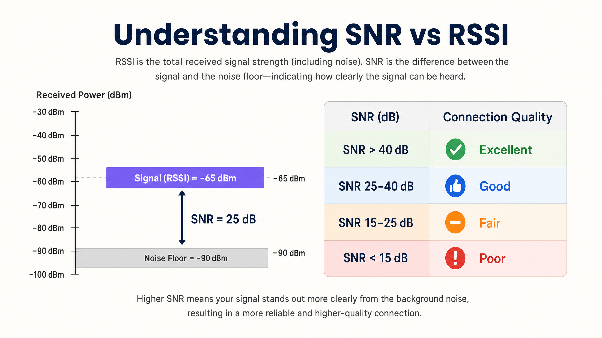
RSSI alone is insufficient for evaluating network quality. Signal-to-Noise Ratio (SNR) provides a more accurate picture of link quality by comparing the received signal strength to the ambient noise floor. An SNR of 25 dB or higher is typically required for high-throughput modulation schemes such as 256-QAM in 802.11ac/ax. If the noise floor is -90 dBm and the RSSI is -65 dBm, the SNR is 25 dB — the minimum threshold for reliable high-performance operation.
The practical implication is significant: a network can display excellent RSSI values on a coverage heatmap yet perform poorly because the noise floor is elevated by non-Wi-Fi interference sources (microwave ovens, DECT phones, Bluetooth devices, or industrial equipment). Always instrument both RSSI and SNR during site surveys and ongoing monitoring.
The Physics of RF Propagation and Attenuation
In complex environments such as hospitals ( Healthcare ) or transit hubs ( Transport ), RF signals suffer attenuation as they pass through physical obstacles. Network architects must account for these material-specific losses when conducting predictive site surveys and defining cell boundaries:
| Material | Typical Attenuation (dB) |
|---|---|
| Drywall / Plasterboard | 3–4 dB |
| Glass (standard) | 2–3 dB |
| Brick | 8–12 dB |
| Concrete | 12–15 dB |
| Reinforced Concrete / Steel | 15–25+ dB |
| Metal Shelving (retail) | 10–20 dB |
The logarithmic nature of the decibel scale is critical to internalise: a 3 dB loss halves the signal power, while a 10 dB loss reduces it by a factor of ten. A signal passing through two brick walls (approximately 20 dB attenuation) is therefore 100 times weaker than the transmitted signal.
Channel Planning: CCI and ACI
Optimal channel planning requires mitigating two distinct interference types. Co-Channel Interference (CCI) occurs when access points operating on the same channel can "hear" each other, leading to medium contention and increased latency due to the CSMA/CA (Carrier-Sense Multiple Access with Collision Avoidance) protocol. Every device on the channel must wait its turn, and when multiple APs are contending simultaneously, channel utilisation spikes even under moderate client load.
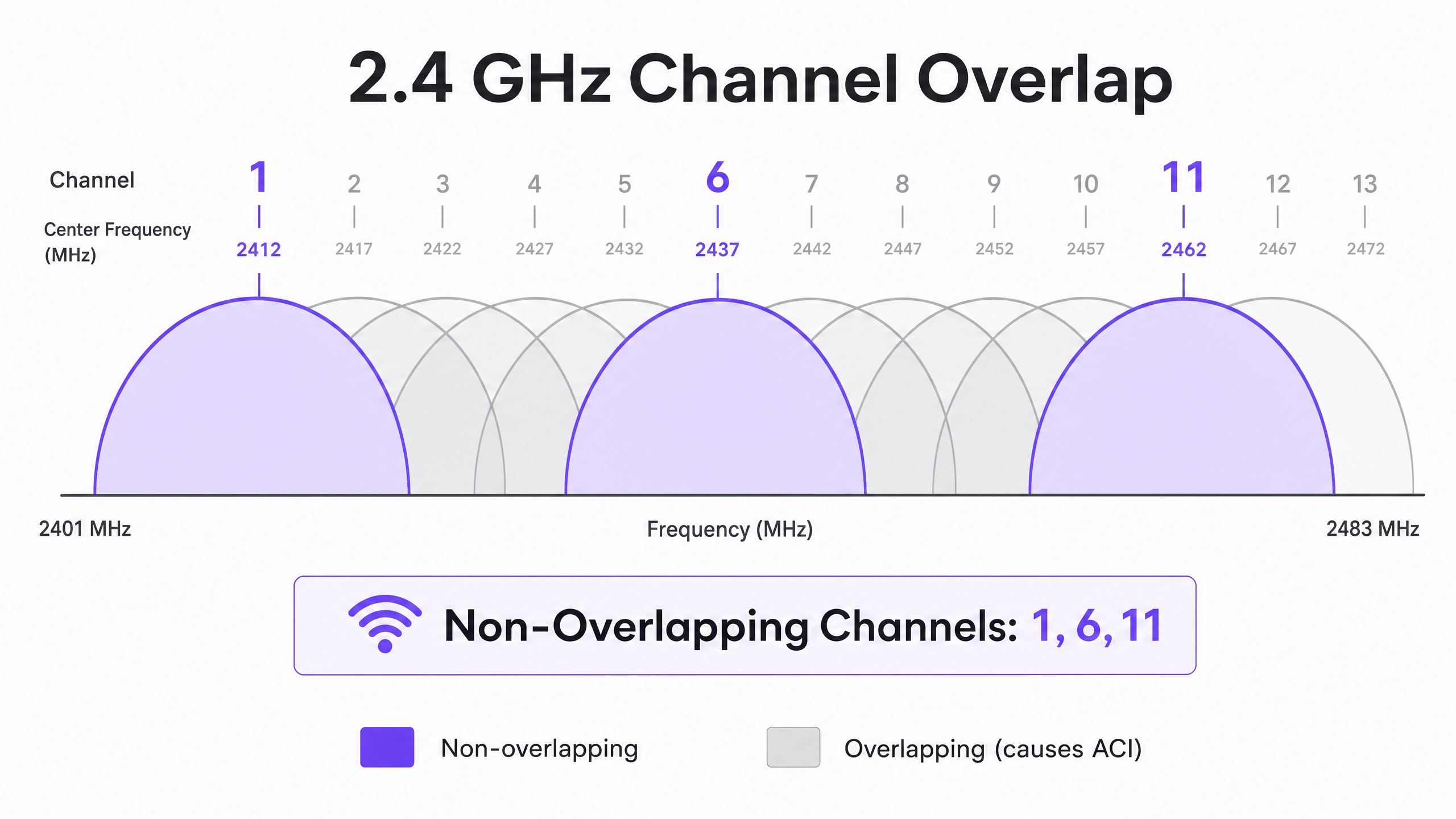
Adjacent Channel Interference (ACI) occurs when APs operate on overlapping channels, raising the noise floor and degrading SNR. In the 2.4 GHz band, only channels 1, 6, and 11 are non-overlapping. Any other channel assignment will cause ACI with one or both of its neighbours. In the 5 GHz band, utilising Dynamic Frequency Selection (DFS) channels expands the available spectrum, though radar detection events can force channel changes, causing brief connectivity disruptions.
When deciding on channel widths, refer to 20MHz vs 40MHz vs 80MHz: Which Channel Width Should You Use? (or the Italian version: 20MHz vs 40MHz vs 80MHz: Quale larghezza di canale dovresti usare? ). The core principle: wider channels deliver higher theoretical throughput but reduce the number of non-overlapping options, increasing CCI in dense deployments.
Implementation Guide
Step 1: Define Requirements and Identify the LCMI Device
Before deploying hardware, define the Primary Coverage Area (PCA) and Secondary Coverage Area (SCA). Critically, identify the Least Capable, Most Important (LCMI) device — the device with the weakest radio that absolutely must operate reliably. This is frequently a legacy handheld scanner in a warehouse, a specific model of medical device in a hospital, or an older smartphone in a hospitality environment. Design the entire RF architecture to meet that device's minimum RSSI requirements, and everything else will perform better.
Step 2: Conduct an Active Site Survey
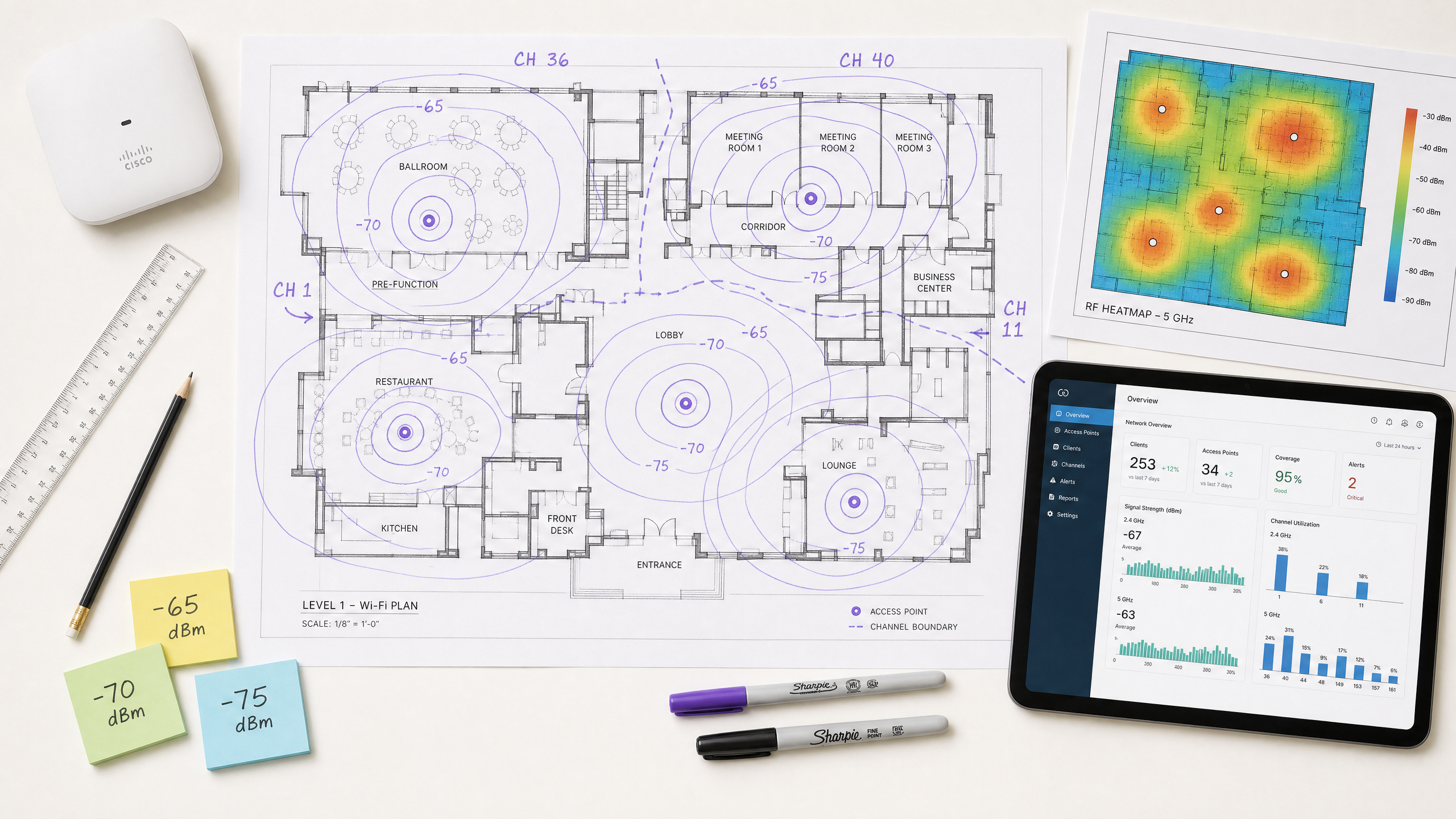
Execute an active site survey to measure real-world RSSI and SNR — not just a predictive survey using software. Use spectrum analysis tools to identify non-Wi-Fi interference sources. Ensure that primary coverage meets the -65 dBm threshold and secondary coverage (for roaming overlap zones) meets -70 dBm. Document the noise floor across all areas, as this will determine achievable SNR and maximum supportable data rates.
Step 3: AP Placement and Power Tuning
Avoid the "louder is better" fallacy. Setting AP transmit power too high creates asymmetric links where the client can hear the AP clearly, but the AP cannot reliably receive the client's weaker transmissions. This is the root cause of the sticky client problem — devices that remain associated with a distant AP despite being physically closer to another. Tune AP transmit power to 10–14 dBm to match client capabilities, and ensure 15–20% cell overlap to facilitate seamless roaming per IEEE 802.11k/v/r.
Step 4: Enforce Minimum Mandatory Data Rates
Disable legacy data rates (1, 2, 5.5, and 11 Mbps in 2.4 GHz; 6 and 9 Mbps in 5 GHz). This raises the minimum RSSI threshold at which a client considers the connection acceptable, forcing earlier roaming decisions and preventing low-rate clients from consuming disproportionate airtime.
Step 5: Integrate Guest WiFi and Analytics
Deploying an enterprise Guest WiFi solution requires seamless authentication that does not degrade the user experience. Implement 802.1X for corporate devices and secure captive portals for guests, with WPA3 where device compatibility permits. Modern approaches such as How a wi fi assistant Enables Passwordless Access in 2026 reduce onboarding friction while maintaining compliance with PCI DSS and GDPR requirements. The RF architecture described in this guide is the prerequisite for reliable analytics and location services — if the RF is poorly designed, the data will be inaccurate.
Best Practices
Design for capacity, not coverage. In modern high-density environments, the constraint is almost never signal reach — it is airtime contention. Deploy more APs at lower transmit power rather than fewer APs at high power. This reduces CCI, improves SNR, and increases the number of clients that can be served simultaneously.
Standardise channel widths by environment. Default to 20 MHz in 2.4 GHz universally. In 5 GHz, use 20 MHz in very high-density environments (stadiums, conference halls) and 40 MHz in moderate-density environments (hotels, retail). Reserve 80 MHz for low-density, high-throughput scenarios only.
Implement the roaming protocol stack. Enable 802.11k (Radio Resource Measurement), 802.11v (BSS Transition Management), and 802.11r (Fast BSS Transition) on all APs. This ensures roaming decisions are driven by RF conditions rather than client inertia, and reduces re-authentication latency from hundreds of milliseconds to under 50 ms.
Validate automatically assigned channels manually. Most enterprise AP vendors offer automatic Radio Resource Management (RRM). While useful as a baseline, RRM can make suboptimal decisions in complex environments. Always audit the channel plan post-deployment and override where necessary.
Monitor continuously, not just at deployment. RF environments change over time — new interference sources appear, occupancy patterns shift, and firmware updates alter radio behaviour. Utilise a WiFi Analytics platform with ongoing RF monitoring to detect degradation before it impacts users.
For broader strategies on leveraging network infrastructure for business outcomes, see How To Improve Guest Satisfaction: The Ultimate Playbook .
Troubleshooting & Risk Mitigation
The Sticky Client Problem
Symptom: Devices remain connected to a distant AP with poor RSSI (-80 dBm) despite being physically closer to a different AP with a strong signal.
Root Cause: AP transmit power is too high, creating an asymmetric link. The client hears the AP well and does not initiate a roam. Alternatively, 802.11k/v protocols are disabled, leaving the client without guidance on better available APs.
Mitigation: Lower AP transmit power to 10–12 dBm. Enable 802.11k/v/r. Set minimum mandatory data rates to force clients to roam when RSSI degrades below the minimum rate threshold.
High Co-Channel Interference
Symptom: Channel utilisation consistently above 40–50% even under moderate client load, resulting in elevated latency and poor throughput.
Root Cause: APs on the same channel are placed too close together, or channel widths are too wide for the deployment density.
Mitigation: Reduce channel width to 20 MHz. Audit the channel plan to maximise physical separation between APs on the same channel. In 2.4 GHz, consider disabling the radio on every other AP in very dense deployments.
Elevated Noise Floor
Symptom: RSSI values look acceptable on heatmaps, but throughput is poor and connections are unstable.
Root Cause: Non-Wi-Fi interference sources (microwave ovens, DECT phones, industrial equipment, Bluetooth) are raising the noise floor, degrading SNR below the threshold required for high-order modulation.
Mitigation: Use a spectrum analyser to identify and characterise interference sources. Migrate affected clients to 5 GHz where possible, as most non-Wi-Fi interference is concentrated in 2.4 GHz. If interference sources cannot be eliminated, increase AP density to improve RSSI and thereby maintain adequate SNR despite the elevated noise floor.
As networks expand into municipal and public spaces, strategic planning becomes increasingly critical. For insights into public sector deployments, read about how Purple Appoints Iain Fox as VP Growth – Public Sector to Drive Digital Inclusion and Smart City Innovation .
ROI & Business Impact
Optimising RSSI and channel planning directly impacts the bottom line across multiple dimensions. The following table summarises the key business outcomes associated with a well-architected wireless network:
| Business Outcome | Mechanism | Typical Impact |
|---|---|---|
| Reduced IT support costs | Fewer connectivity complaints; fewer site visits | 20–40% reduction in Wi-Fi-related support tickets |
| Improved guest satisfaction | Reliable, high-speed connectivity throughout the venue | Measurable improvement in NPS and review scores |
| Accurate location analytics | Sufficient AP density and SNR for reliable trilateration | Sub-3-metre location accuracy for footfall analytics |
| First-party data capture | Reliable captive portal performance | Higher completion rates on guest Wi-Fi onboarding |
| Operational efficiency | Reliable connectivity for handheld devices, POS systems, IoT | Reduced transaction failures and operational downtime |
For venue operators, reliable Wi-Fi is no longer a cost centre but a revenue enabler. By ensuring consistent signal strength and high SNR, venues can confidently deploy captive portals to capture first-party data, driving personalised marketing campaigns and increasing customer lifetime value. The investment in proper RF design yields measurable ROI through operational efficiency, enhanced digital engagement, and the ability to deploy advanced analytics and location services with confidence.
Purple's hardware-agnostic platform integrates with existing infrastructure to provide the analytics layer on top of a well-designed RF foundation — turning signal strength data into actionable business intelligence across Hospitality , Retail , Healthcare , and Transport environments.
Key Definitions
RSSI (Received Signal Strength Indicator)
A relative measurement of the power level of an RF signal received by a client device, expressed in negative dBm. The closer to zero, the stronger the signal.
Used to determine coverage boundaries, trigger roaming decisions, and assess basic signal availability. Not sufficient on its own to evaluate link quality.
SNR (Signal-to-Noise Ratio)
The difference in decibels (dB) between the received signal strength and the ambient noise floor. Calculated as: SNR (dB) = RSSI (dBm) − Noise Floor (dBm).
The primary determinant of achievable modulation scheme and data rate. An SNR of 25 dB is the minimum for 256-QAM (high-throughput) operation. Always measure alongside RSSI.
CCI (Co-Channel Interference)
Interference that occurs when multiple APs and clients operate on the same channel and can detect each other's transmissions, causing medium contention under the CSMA/CA protocol.
The most common cause of high channel utilisation and latency in enterprise deployments. Mitigated by proper channel planning, power tuning, and ensuring adequate physical separation between APs on the same channel.
ACI (Adjacent Channel Interference)
Interference caused by RF energy from one channel bleeding into an adjacent overlapping channel, raising the noise floor and degrading SNR.
Caused by using overlapping channels in the 2.4 GHz band (anything other than 1, 6, 11). Avoided by strict adherence to non-overlapping channel assignments.
DFS (Dynamic Frequency Selection)
A regulatory mechanism that allows Wi-Fi devices to share the 5 GHz spectrum with radar systems by monitoring for radar signals and vacating the channel if detected.
Expands the available 5 GHz channel set, but requires APs to change channels upon radar detection, causing a brief connectivity disruption. Must be accounted for in deployments near airports, military installations, or weather radar sites.
CSMA/CA (Carrier-Sense Multiple Access with Collision Avoidance)
The medium access protocol used by Wi-Fi, in which devices listen to the RF channel before transmitting and defer if the channel is busy.
The fundamental reason Wi-Fi is a half-duplex, shared medium. CCI forces multiple APs and clients to contend for the same channel, which is why channel planning is critical to performance.
Sticky Client
A client device that remains associated with an AP delivering a weak signal despite being physically closer to a different AP with a stronger signal.
Caused by asymmetric link budgets (AP transmit power too high) or absence of 802.11k/v roaming protocols. Results in poor throughput, high latency, and degraded user experience.
LCMI (Least Capable, Most Important) Device
The device in a deployment with the weakest radio capabilities that is nonetheless critical to business operations.
Used as the design baseline for RF architecture. Designing to meet the LCMI device's requirements ensures all other devices perform adequately.
802.11k/v/r
A suite of IEEE 802.11 amendments: 802.11k (Radio Resource Measurement), 802.11v (BSS Transition Management), and 802.11r (Fast BSS Transition).
Together, these protocols enable intelligent, low-latency client roaming. 802.11k provides neighbour reports, 802.11v enables network-directed roaming, and 802.11r reduces re-authentication time to under 50 ms.
Worked Examples
A 300-room hotel is experiencing poor Wi-Fi performance in guest rooms despite having an AP in every corridor. Guests report dropped connections and slow speeds, particularly in rooms furthest from the corridor APs. The existing APs are configured at maximum transmit power (23 dBm) on auto channel assignment.
The root cause is a combination of Co-Channel Interference (CCI) from corridor APs hearing each other down the long hallways, signal attenuation through guest room doors and walls, and the sticky client problem caused by excessively high transmit power. The recommended solution is to transition to an in-room AP deployment model using wall-plate APs (e.g., Cisco Catalyst 9105AXW or Aruba AP-303H). Configure each AP with a transmit power of 10–12 dBm. Disable 2.4 GHz on every other AP in the corridor to reduce CCI. Standardise on 20 MHz channels in 5 GHz with a manual channel plan assigning channels 36, 40, 44, 48, 52, 56, 60, 64 in a repeating pattern. Enable 802.11k/v/r on all APs. Set minimum mandatory data rates to 12 Mbps in 2.4 GHz and 24 Mbps in 5 GHz. Validate with a post-deployment active site survey targeting -65 dBm RSSI and 25 dB SNR in all guest rooms.
A large retail chain operating 50,000 sq ft stores wants to deploy Wi-Fi location analytics to track customer footfall and dwell time by department. Initial data from the existing network shows location accuracy of ±15 metres, which is insufficient for department-level analysis. The existing infrastructure has APs mounted at 6-metre intervals along the central spine of the store.
Location analytics based on RSSI trilateration require a minimum of three APs to hear a client device simultaneously, with each AP receiving a signal of -75 dBm or better. The current linear AP layout means that in the outer departments, clients are only within range of one or two APs, making accurate trilateration impossible. The solution requires a redesigned AP layout using a staggered grid pattern with APs at the perimeter and interior of each department zone, ensuring that any point on the floor is within -75 dBm range of at least three APs. Reduce AP transmit power to 10 dBm to tighten RF cells and improve the differential between AP readings (which is what drives location accuracy). Enable 802.11k/v to ensure devices don't stick to distant APs, which skews location data. Integrate the AP infrastructure with Purple's WiFi Analytics platform to process RSSI data into footfall heatmaps and dwell time reports by department.
Practice Questions
Q1. You are designing a Wi-Fi network for a 40,000-seat stadium. The venue operator wants maximum throughput for concurrent video streaming and social media uploads during events. You are considering using 80 MHz channels in the 5 GHz band to maximise per-client throughput. Is this the recommended approach, and what channel plan would you implement instead?
Hint: Consider the number of non-overlapping 80 MHz channels available in the 5 GHz band versus 20 MHz channels, and the impact of Co-Channel Interference in an open, high-density environment.
View model answer
No. Using 80 MHz channels in a stadium is strongly contraindicated. In the standard 5 GHz UNII-1/2/2e bands, there are only a handful of non-overlapping 80 MHz channels, meaning that with the AP density required for 40,000 concurrent users, severe CCI is inevitable. The correct approach is to use 20 MHz channels throughout, which provides up to 24 non-overlapping channels in 5 GHz (including DFS), maximising channel reuse. Directional sector antennas should be used to tightly control RF cell coverage, pointing down into seating sections rather than radiating omnidirectionally. AP density should be calculated based on a target of no more than 30–50 clients per AP radio, with transmit power tuned to match the coverage area of each sector.
Q2. A warehouse deployment uses handheld barcode scanners that frequently drop connections when operators move between aisles. The APs are configured at maximum transmit power (23 dBm) to ensure full coverage. The scanners run a legacy WMS application that requires sub-100ms latency. What is the likely cause and what steps would you take to resolve it?
Hint: Consider the transmit power capabilities of a small handheld scanner versus an enterprise AP, and the implications for the link budget in both directions.
View model answer
The likely cause is the sticky client problem resulting from an asymmetric link budget. The APs are transmitting at 23 dBm, so the scanners hear them well across the entire warehouse and do not initiate a roam. However, the scanners' internal radios typically transmit at only 15–17 dBm, meaning the AP cannot reliably receive the scanner's transmissions when it is far away. The solution is to lower AP transmit power to 10–12 dBm to match the scanners' capabilities, ensuring that the coverage cells are appropriately sized and that scanners roam when they move out of range. Enable 802.11k/v/r to facilitate fast roaming. Set minimum mandatory data rates to 12 Mbps to force earlier roaming decisions. Validate with an active site survey using the actual scanner hardware to confirm -65 dBm RSSI and 25 dB SNR throughout all aisles.
Q3. During a site survey for a new hospital wing, you measure an RSSI of -58 dBm from the primary AP throughout the target area. However, the noise floor measured by a spectrum analyser is consistently -72 dBm due to legacy medical monitoring equipment operating in the 2.4 GHz band. The hospital requires reliable VoWiFi for clinical communications. Will this network support VoWiFi, and what actions would you recommend?
Hint: Calculate the SNR and evaluate it against the minimum requirement for VoWiFi. Consider which frequency band is affected and what mitigation options are available.
View model answer
No, this network will not reliably support VoWiFi in its current state. The SNR is calculated as -58 dBm - (-72 dBm) = 14 dB. This falls below the minimum 20 dB SNR required for VoWiFi and well below the 25 dB target for high-quality voice. Despite the strong RSSI of -58 dBm, the elevated noise floor from the medical equipment degrades the link quality to an unacceptable level. Recommended actions: First, migrate VoWiFi traffic to the 5 GHz band, which is largely unaffected by the legacy 2.4 GHz medical equipment. Second, increase AP density in the affected areas to improve RSSI to -50 dBm or better, which would yield an SNR of 22 dB even with the elevated noise floor — marginally acceptable for VoWiFi. Third, engage the biomedical engineering team to assess whether the legacy equipment can be replaced or shielded. Fourth, implement QoS (WMM) with voice traffic prioritisation to protect VoWiFi traffic from competing with data traffic during periods of congestion.