Fixing High Latency and Jitter on Staff WiFi
This authoritative technical reference guide examines the root causes of high latency and jitter on enterprise staff WiFi networks, providing network architects and IT directors with actionable strategies to diagnose and resolve performance degradation affecting real-time applications such as Microsoft Teams and Zoom. It covers RF environment optimisation, end-to-end QoS implementation, roaming mechanics, and client management techniques. Venue operators and IT teams will find concrete implementation guidance, real-world case studies, and measurable benchmarks to ensure their wireless infrastructure supports seamless staff mobility and collaboration.
Listen to this guide
View podcast transcript
कार्यकारी सारांश
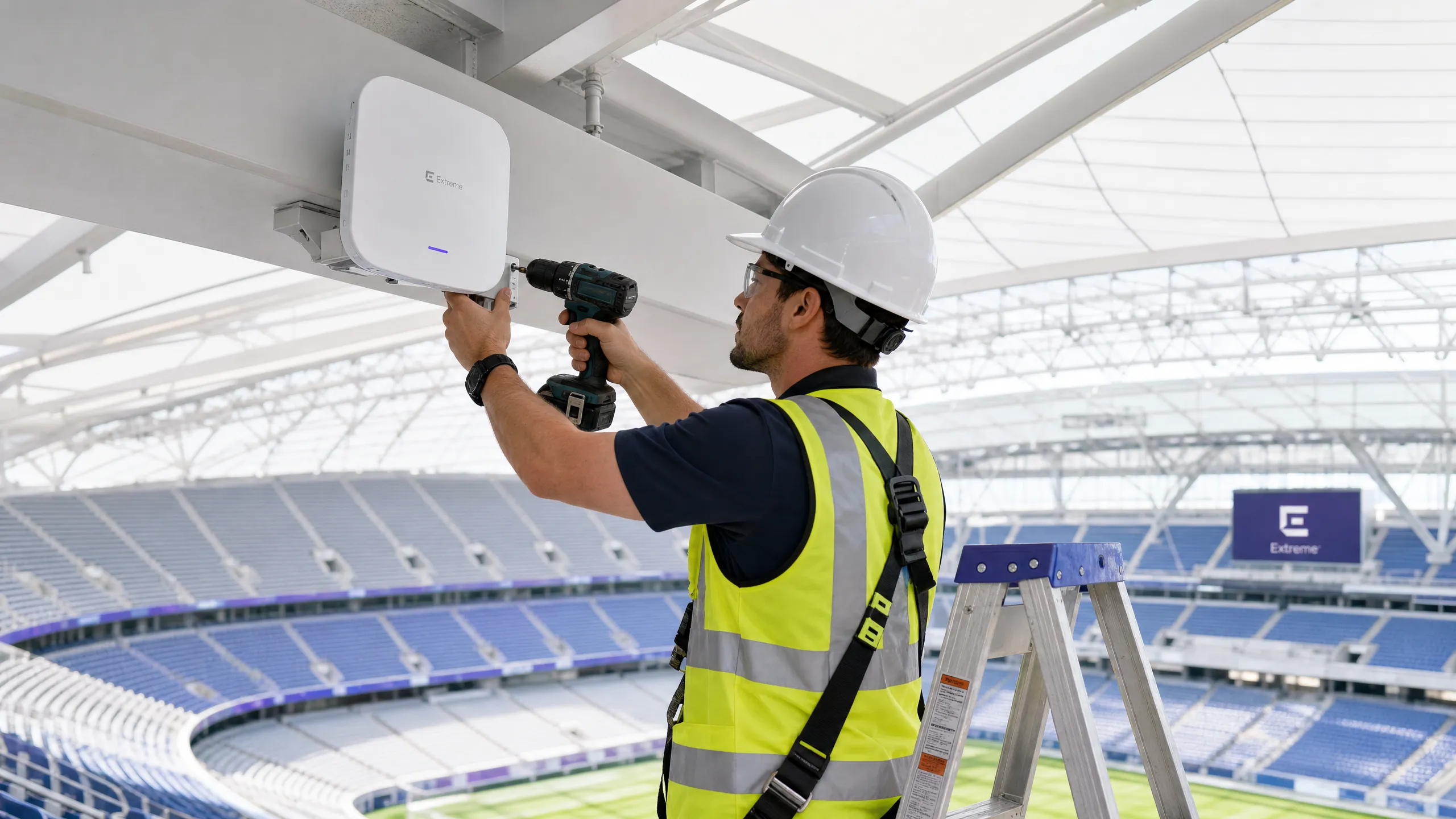
एंटरप्राइज वेन्यू के लिए — विस्तृत रिटेल फ्लोर से लेकर हाई-डेंसिटी स्टेडियमों और हॉस्पिटैलिटी संपत्तियों तक — स्टाफ WiFi प्रदर्शन एक महत्वपूर्ण परिचालन निर्भरता है, न कि केवल एक सुविधा। जब वन-वे लेटेंसी 50ms से अधिक हो जाती है या जिटर 20ms से आगे बढ़ जाता है, तो Microsoft Teams और Zoom सहित रीयल-टाइम कम्युनिकेशन प्लेटफॉर्म का प्रदर्शन स्पष्ट रूप से गिर जाता है: ऑडियो रोबोटिक हो जाता है, वीडियो फ्रीज हो जाता है, और कॉल ड्रॉप होने लगती हैं। यह गाइड नेटवर्क आर्किटेक्ट्स और IT निदेशकों को कॉर्पोरेट WLANs पर हाई लेटेंसी WiFi के मूल कारणों की पहचान करने, निदान करने और उन्हें हल करने के लिए आवश्यक तकनीकी गहराई और व्यावहारिक रणनीतियाँ प्रदान करती है। RF हस्तक्षेप को संबोधित करके, एंड-टू-एंड Quality of Service को लागू करके, और IEEE 802.11r/k/v के अनुरूप रोमिंग पैरामीटर को ट्यून करके, संगठन एक मजबूत वायरलेस अनुभव प्रदान कर सकते हैं जो निर्बाध स्टाफ मोबिलिटी का समर्थन करता है। यह निवेश सीधे मापने योग्य है: हेल्पडेस्क टिकटों में कमी, बेहतर परिचालन थ्रूपुट, और एक ऐसा नेटवर्क इन्फ्रास्ट्रक्चर जो व्यवसाय के साथ स्केल करता है।
तकनीकी गहन विश्लेषण
लेटेंसी और जिटर: मुख्य अंतर
लेटेंसी वह समय है जो एक डेटा पैकेट को स्रोत से गंतव्य तक यात्रा करने के लिए आवश्यक होता है। जिटर लगातार पैकेटों के बीच उस देरी में होने वाला उतार-चढ़ाव है। 802.11 नेटवर्क के संदर्भ में, दोनों मेट्रिक्स वायरलेस ट्रांसमिशन की हाफ-डुप्लेक्स प्रकृति और Carrier Sense Multiple Access with Collision Avoidance (CSMA/CA) प्रोटोकॉल — वह तंत्र जिसके द्वारा डिवाइस एयरटाइम के लिए प्रतिस्पर्धा करते हैं — से भारी रूप से प्रभावित होते हैं।
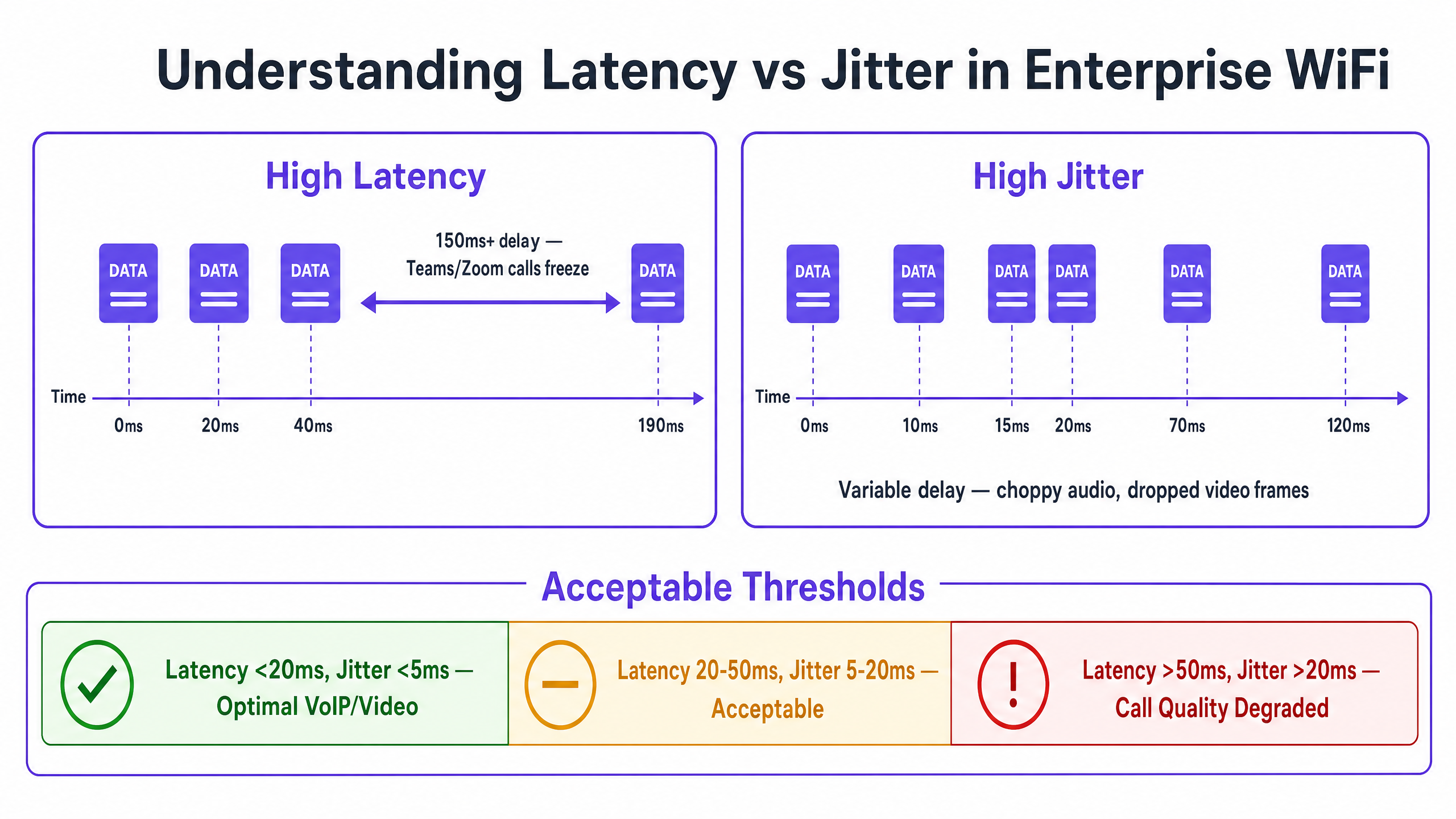
वॉयस और वीडियो कोडेक्स को फिक्स्ड जिटर बफ़र्स के साथ डिज़ाइन किया गया है। जब जिटर बफ़र की गहराई से अधिक हो जाता है — आमतौर पर एंटरप्राइज-ग्रेड VoIP के लिए 20-30ms — तो पैकेट खारिज कर दिए जाते हैं, जिससे विशिष्ट कटी-फटी या रोबोटिक ऑडियो उत्पन्न होती है जो कॉल के खराब होने का संकेत देती है। इसके विपरीत, हाई लेटेंसी बातचीत में देरी का कारण बनती है जिससे रीयल-टाइम सहयोग कठिन हो जाता है। ITU-T G.114 सिफारिश स्वीकार्य वॉयस क्वालिटी के लिए अधिकतम 150ms की वन-वे देरी को निर्दिष्ट करती है, जिसमें एंटरप्राइज डिप्लॉयमेंट के लिए 50ms का लक्ष्य रखा गया है।
| मीट्रिक | इष्टतम | स्वीकार्य | डिग्रेडेड |
|---|---|---|---|
| वन-वे लेटेंसी | < 20ms | 20–50ms | > 50ms |
| जिटर | < 5ms | 5–20ms | > 20ms |
| पैकेट लॉस | < 0.1% | 0.1–1% | > 1% |
मूल कारण 1: RF वातावरण और को-चैनल हस्तक्षेप (Co-Channel Interference)
को-चैनल हस्तक्षेप (CCI) घने एंटरप्राइज डिप्लॉयमेंट में बढ़ी हुई लेटेंसी का प्राथमिक RF कारण है। जब कई एक्सेस पॉइंट (APs) एक ही चैनल पर काम करते हैं, तो वे CSMA/CA के तहत एयरटाइम साझा करते हैं। प्रत्येक AP को ट्रांसमिशन को तब तक टालना पड़ता है जब तक कि वह उसी चैनल पर किसी अन्य AP को ट्रांसमिट करते हुए डिटेक्ट करता है, जिससे ट्रैफ़िक प्रभावी रूप से क्रमिक हो जाता है और कतारबद्ध होने की देरी बढ़ जाती है। तीन नॉन-ओवरलैपिंग 2.4GHz चैनलों पर 20 APs वाले एक रिटेल स्टोर में, प्रत्येक चैनल को छह या सात APs द्वारा साझा किया जा सकता है — एक ऐसा कॉन्फ़िगरेशन जो लोड के तहत महत्वपूर्ण लेटेंसी पैदा करेगा।
5GHz बैंड, अपने व्यापक चैनल प्लान (कई नियामक क्षेत्रों में 802.11ac/ax के तहत 25 नॉन-ओवरलैपिंग 20MHz चैनलों तक) के साथ, चैनल पुन: उपयोग योजना के लिए काफी अधिक क्षमता प्रदान करता है। पूर्ण आवृत्ति परिदृश्य को समझना आवश्यक है; गाइड Wi Fi Frequencies: A Guide to Wi-Fi Frequencies in 2026 आवृत्ति योजना के निर्णयों के लिए एक व्यापक संदर्भ प्रदान करता है।
आसन्न चैनल हस्तक्षेप (Adjacent Channel Interference - ACI) एक द्वितीयक जोखिम प्रस्तुत करता है। ACI तब होता है जब चैनल पर्याप्त रूप से अलग नहीं होते हैं, जिससे आंशिक ओवरलैप होता है जो फ्रेम को दूषित करता है और पुन: प्रसारण के लिए मजबूर करता है — प्रत्येक रीट्रांसमिशन सीधे देखी गई लेटेंसी को बढ़ाता है।
मूल कारण 2: लीगेसी डेटा दरें और एयरटाइम अक्षमता
एक मानक 802.11 BSS में, सभी संबद्ध क्लाइंट्स को ट्रांसमिशन के अवसर आवंटित किए जाते हैं। 1 Mbps पर ट्रांसमिट करने वाला क्लाइंट उसी पेलोड को भेजने के लिए 100 Mbps पर ट्रांसमिट करने वाले क्लाइंट की तुलना में लगभग 100 गुना अधिक समय तक चैनल पर कब्जा रखता है। यह असमान एयरटाइम खपत — जो लीगेसी डिवाइसों या कवरेज के किनारे पर मौजूद क्लाइंट्स के कारण होती है — AP पर अन्य सभी क्लाइंट्स के लिए कतारबद्ध होने की देरी को बढ़ाती है। 5GHz बैंड पर 12 Mbps से कम और 2.4GHz पर 5.5 Mbps से कम की डेटा दरों को अक्षम करने से क्लाइंट्स अधिक कुशल मॉड्यूलेशन का उपयोग करने के लिए मजबूर होते हैं, जिससे प्रति-फ्रेम एयरटाइम कम होता है और समग्र लेटेंसी में सुधार होता है।
मूल कारण 3: QoS गलत कॉन्फ़िगरेशन
Quality of Service के बिना, एक बल्क फ़ाइल ट्रांसफर को बिल्कुल Teams कॉल की तरह ही माना जाता है। Wi-Fi Multimedia (WMM), जो कि 802.11e QoS कार्यान्वयन है, चार एक्सेस श्रेणियों को परिभाषित करता: Voice (AC_VO), Video (AC_VI), Best Effort (AC_BE), और Background (AC_BK)। प्रत्येक श्रेणी में अलग-अलग कंटेंशन विंडो पैरामीटर होते हैं जो यह निर्धारित करते हैं कि यह एयरटाइम के लिए कितनी आक्रामक रूप से प्रतिस्पर्धा करती है। वॉयस ट्रैफ़िक छोटी कंटेंशन विंडो और छोटे आर्बिट्रेशन इंटर-फ्रेम स्पेस (AIFS) का उपयोग करता है, जिससे इसे बल्क डेटा पर सांख्यिकीय प्राथमिकता मिलती है।
महत्वपूर्ण कार्यान्वयन विवरण जिसे कई डिप्लॉयमेंट अनदेखा कर देते हैं, वह वायर्ड इन्फ्रास्ट्रक्चर पर ट्रस्ट बाउंड्री है। WMM वायरलेस डोमेन के भीतर लेयर 2 पर काम करता है। QoS को एंड-टू-एंड बनाए रखने के लिए, APs और वायरलेस LAN कंट्रोलर्स को जोड़ने वाले स्विच पोर्ट्स को वायरलेस इन्फ्रास्ट्रक्चर द्वारा लागू की गई DSCP मार्किंग्स पर भरोसा करने के लिए कॉन्फ़िगर किया जाना चाहिए। इसके बिना, पैकेटों को पहले वायर्ड हॉप पर Best Effort में पुन: वर्गीकृत किया जाता है, जिससे वायरलेस QoS कॉन्फ़िगरेशन AP के आगे अप्रभावी हो जाता है।
हेल्थकेयर वातावरण के लिए जहां VoWLAN पर क्लिनिकल संचार सुरक्षा-महत्वपूर्ण है, यह एंड-टू-एंड QoS चेन गैर-परक्राम्य है।
मूल कारण 4: रोमिंग लेटेंसी और ऑथेंटिकेशन ओवरहेड
मोबाइल स्टाफ वातावरण में कॉल की गुणवत्ता में गिरावट का सबसे अधिक परिचालन रूप से विघटनकारी कारण रोमिंग-प्रेरित लेटेंसी है। जब कोई क्लाइंट APs के बीच ट्रांजिशन करता है, तो इस प्रक्रिया में शामिल हैं: संभावित APs की खोज के लिए सक्रिय या निष्क्रिय स्कैनिंग, ऑथेंटिकेशन और री-एसोसिएशन। 802.1X के साथ WPA3-Enterprise के तहत, ऑथेंटिकेशन चरण के लिए एक पूर्ण RADIUS एक्सचेंज की आवश्यकता होती है, जिसमें RADIUS सर्वर प्रतिक्रिया समय और नेटवर्क टोपोलॉजी के आधार पर 300-800ms लग सकते हैं। यह देरी सीधे कॉल ड्रॉपआउट के रूप में अनुभव की जाती है।
IEEE 802.11r (Fast BSS Transition) क्लाइंट को रोमिंग से पहले लक्षित AP के साथ पेयरवाइज ट्रांजिएंट की (Pairwise Transient Key) को प्री-नेगोशिएट करने की अनुमति देकर इसे हल करता है, जिसके लिए WLC द्वारा वितरित कैश्ड PMK-R1 की का उपयोग किया जाता है। यह ऑथेंटिकेशन चरण को दो-फ्रेम एक्सचेंज तक कम कर देता है, जिससे कुल रोमिंग समय 50ms से नीचे आ जाता है। महत्वपूर्ण स्टाफ मोबिलिटी वाले वातावरणों के लिए — ट्रांसपोर्ट हब, अस्पताल के वार्ड, वेयरहाउस फ्लोर — 802.11r वैकल्पिक नहीं है; यह एक आधारभूत आवश्यकता है।
IEEE 802.11k (Radio Resource Measurement) क्लाइंट्स को एक नेबर रिपोर्ट (Neighbour Report) प्रदान करता है, जिससे संभावित APs की खोज के लिए हर संभव चैनल को स्कैन करने की आवश्यकता समाप्त हो जाती है। IEEE 802.11v (BSS Transition Management) नेटवर्क को सक्रिय रूप से क्लाइंट्स को बेहतर APs का सुझाव देने की अनुमति देता है, जिससे स्टिकी क्लाइंट की समस्या का समाधान होता है। रोमिंग आर्किटेक्चर के व्यापक विवरण के लिए, Resolving Roaming Issues in Corporate WLANs देखें।
कार्यान्वयन गाइड
चरण 1: RF ऑडिट और चैनल प्लानिंग
हस्तक्षेप के स्रोतों की पहचान करने के लिए स्पेक्ट्रम एनालाइजर का उपयोग करके एक व्यापक वायरलेस साइट सर्वे से शुरुआत करें, जिसमें ब्लूटूथ, DECT फोन और माइक्रोवेव ओवन जैसे गैर-WiFi स्रोत शामिल हैं। AP प्लेसमेंट, ट्रांसमिट पावर लेवल और चैनल असाइनमेंट का दस्तावेजीकरण करें। लगातार 50% से अधिक चैनल उपयोग वाले APs की पहचान करें — ये आपके प्राथमिक लेटेंसी हॉटस्पॉट हैं।
पर्याप्त कवरेज बनाए रखने के लिए आवश्यक न्यूनतम स्तर तक AP ट्रांसमिट पावर को कम करें (वॉयस अनुप्रयोगों के लिए सेल एज पर -67 dBm RSSI)। यह प्रत्येक AP के CCI फ़ुटप्रिंट को कम करता है, जिससे सघन चैनल पुन: उपयोग की अनुमति मिलती है। WLC पर स्वचालित RF प्रबंधन सक्षम करें, लेकिन व्यावसायिक घंटों के दौरान चैनल परिवर्तनों को रोकने के लिए समय-प्रतिबंध कॉन्फ़िगर करें, जिससे संक्षिप्त कनेक्टिविटी रुकावटें हो सकती हैं।
चरण 2: डेटा दर अनुकूलन
5GHz बैंड पर, 12 Mbps से नीचे की सभी अनिवार्य और समर्थित दरों को अक्षम करें। 2.4GHz बैंड पर, 5.5 Mbps से नीचे की दरों को अक्षम करें। यह क्लाइंट्स को उच्च दरों पर संबद्ध होने के लिए मजबूर करता है, जिससे प्रति-फ्रेम एयरटाइम खपत कम होती है। किसी भी एकल क्लाइंट को चैनल पर एकाधिकार करने से रोकने के लिए Airtime Fairness सक्षम करें।
चरण 3: एंड-टू-एंड QoS कार्यान्वयन
सभी कॉर्पोरेट SSIDs पर WMM सक्षम करें। DSCP-से-WMM मैपिंग कॉन्फ़िगर करें: DSCP EF (46) को AC_VO, DSCP AF41 (34) को AC_VI। वायर्ड इन्फ्रास्ट्रक्चर पर, APs और WLCs से जुड़ने वाले स्विच पोर्ट्स को mls qos trust dscp (Cisco IOS सिंटैक्स) या समकक्ष के साथ कॉन्फ़िगर करें। WAN राउटर पर पैकेट कैप्चर का उपयोग करके QoS चेन को सत्यापित करें ताकि यह पुष्टि हो सके कि वॉयस ट्रैफ़िक सही DSCP मार्किंग्स के साथ आ रहा है।
असमान एयरटाइम की खपत करने वाले बैंडविड्थ-गहन अनुप्रयोगों की पहचान करने के लिए गेस्ट WiFi का उपयोग करें, और वॉयस तथा वीडियो ट्रैफ़िक की सुरक्षा के लिए रेट लिमिट या ट्रैफ़िक शेपिंग नीतियां लागू करें।
चरण 4: रोमिंग अनुकूलन
स्टाफ SSID पर 802.11r, 802.11k, और 802.11v सक्षम करें। ध्यान दें कि कुछ लीगेसी क्लाइंट इन मानकों का समर्थन नहीं कर सकते हैं; डिप्लॉयमेंट से पहले पूरी तरह से परीक्षण करें। स्टिकी क्लाइंट्स की समस्या को हल करने के लिए -75 dBm से नीचे RSSI वाले क्लाइंट्स को डिस्कनेक्ट करने के लिए WLC को कॉन्फ़िगर करें। क्लाइंट्स को दूर के APs से जुड़ने से रोकने के लिए एसोसिएशन के लिए न्यूनतम RSSI थ्रेशोल्ड को -80 dBm पर सेट करें।
सर्वोत्तम प्रथाएं
सुरक्षा और प्रदर्शन: स्टाफ SSID के लिए 802.1X के साथ WPA3-Enterprise डिप्लॉय करें। हालांकि 802.1X प्रारंभिक ऑथेंटिकेशन ओवरहेड पेश करता है, लेकिन 802.11r रोमिंग के दौरान इसे समाप्त कर देता है। सुनिश्चित करें कि RADIUS सर्वर रिडंडेंसी और 100ms से कम प्रतिक्रिया समय के साथ डिप्लॉय किए गए हैं। GDPR और PCI DSS का अनुपालन आवश्यक बनाता है कि स्टाफ और Guest WiFi ट्रैफ़िक को VLANs और अलग SSIDs का उपयोग करके तार्किक रूप से अलग किया जाए।
नेटवर्क सेगमेंटेशन: स्टाफ और गेस्ट नेटवर्क के बीच सख्त अलगाव बनाए रखें। गेस्ट ट्रैफ़िक को Captive Portal ऑथेंटिकेशन के साथ एक समर्पित SSID पर अलग किया जाना चाहिए, जिससे गेस्ट डिवाइस स्टाफ नेटवर्क के प्रदर्शन को प्रभावित न कर सकें। यह विशेष रूप से हॉस्पिटैलिटी संपत्तियों के लिए प्रासंगिक है जहां गेस्ट WiFi डेंसिटी अत्यधिक उच्च हो सकती है।
निगरानी और बेसलाइनिंग: ऑफ-पीक घंटों के दौरान बेसलाइन लेटेंसी और जिटर माप स्थापित करें। 50% से अधिक चैनल उपयोग या क्लाइंट RSSI के -70 dBm से नीचे गिरने पर अलर्ट करने के लिए SNMP ट्रैप या स्ट्रीमिंग टेलीमेट्री कॉन्फ़िगर करें। सक्रिय निगरानी प्रतिक्रियाशील समस्या निवारण को रोकती है।
व्यापक कार्यस्थल कनेक्टिविटी रणनीति के लिए, Office Wi Fi: Optimize Your Modern Office Wi-Fi Network एंटरप्राइज WLAN डिज़ाइन पर पूरक मार्गदर्शन प्रदान करता है।
समस्या निवारण और जोखिम शमन
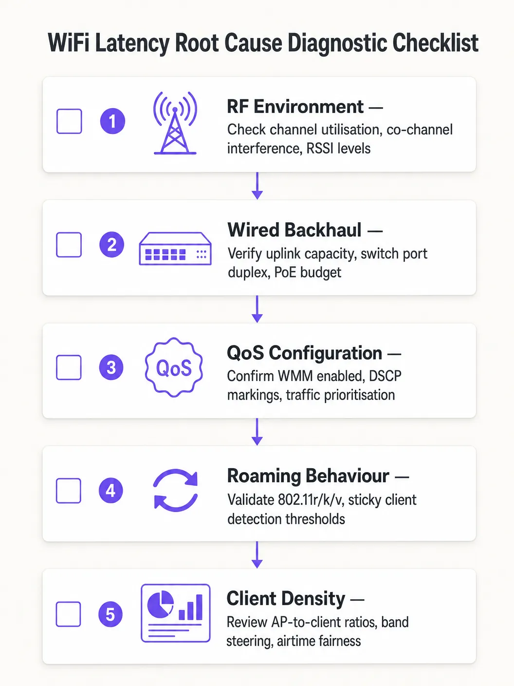
मूल कारण का गलत अनुमान लगाने से बचने के लिए एक संरचित नैदानिक दृष्टिकोण का पालन करें:
- डोमेन को अलग करें: प्रभावित क्लाइंट से स्थानीय डिफॉल्ट गेटवे को पिंग करें। यदि लेटेंसी कम है, तो वायरलेस नेटवर्क पर्याप्त रूप से प्रदर्शन कर रहा है और समस्या वायर्ड या WAN डोमेन में है। यदि लेटेंसी अधिक है, तो वायरलेस डायग्नोस्टिक्स के साथ आगे बढ़ें।
- चैनल उपयोग की जांच करें: उच्च उपयोग (>50%) CCI या क्षमता की कमी को दर्शाता है। उच्च लेटेंसी के साथ कम उपयोग QoS या रोमिंग समस्याओं की ओर इशारा करता है।
- क्लाइंट एसोसिएशन की समीक्षा करें: कम डेटा दरों पर या कमजोर RSSI के साथ जुड़े क्लाइंट्स की पहचान करें। ये संभवतः एयरटाइम अक्षमता का कारण बन रहे हैं या खराब कवरेज का अनुभव कर रहे हैं।
- एंड-टू-एंड QoS को मान्य करें: WAN इंटरफ़ेस पर पैकेट कैप्चर करें और वॉयस ट्रैफ़िक पर DSCP मार्किंग्स को सत्यापित करें।
- रोमिंग का परीक्षण करें: रोमिंग ट्रांजिशन समय को मापने के लिए एक WiFi डायग्नोस्टिक टूल का उपयोग करें। 100ms से ऊपर कुछ भी यह दर्शाता है कि 802.11r ठीक से काम नहीं कर रहा है।
सामान्य विफलता मोड:
| लक्षण | संभावित कारण | समाधान |
|---|---|---|
| पीक आवर्स के दौरान लेटेंसी स्पाइक्स | CCI / उच्च चैनल उपयोग | AP पावर कम करें, 5GHz पर माइग्रेट करें |
| चलते समय ऑडियो ड्रॉपआउट | धीमी रोमिंग / 802.11r का न होना | 802.11r सक्षम करें, RSSI थ्रेशोल्ड ट्यून करें |
| लगातार उच्च लेटेंसी, कम उपयोग | QoS ट्रस्ट बाउंड्री गायब होना | स्विच पोर्ट्स पर DSCP ट्रस्ट कॉन्फ़िगर करें |
| रुक-रुक कर पैकेट लॉस | ACI / चैनल ओवरलैप | चैनल प्लान को सही करें, चैनल सेपरेशन बढ़ाएं |
ROI और व्यावसायिक प्रभाव
WiFi लेटेंसी अनुकूलन के लिए बिजनेस केस सीधा है। वेयरहाउस या लॉजिस्टिक्स ऑपरेशन में, स्कैनर लेटेंसी को 150ms से घटाकर 20ms से कम करने से पिक-एंड-पैक थ्रूपुट में 10-15% की वृद्धि हो सकती है, जो सीधे परिचालन लागत को प्रभावित करती है। कॉर्पोरेट वातावरण में, ड्रॉप होने वाली Teams कॉल्स को समाप्त करने से IT हेल्पडेस्क टिकटों में कमी आती है — जिन्हें हल करने में आमतौर पर प्रति टिकट £25-£50 की लागत आती है — और अधिकारियों तथा कर्मचारियों की उत्पादकता में सुधार होता है।
क्लिनिकल संचार के लिए VoWLAN डिप्लॉय करने वाले हेल्थकेयर संगठनों के लिए, जोखिम शमन का मूल्य और भी अधिक है: क्लिनिकल सेटिंग में अविश्वसनीय संचार रोगी सुरक्षा से जुड़े ऐसे निहितार्थ पैदा करता है जिसके सामने नेटवर्क अनुकूलन की लागत बहुत छोटी है।
इन KPIs के आधार पर सफलता को मापें: वॉयस ट्रैफ़िक के लिए औसत वन-वे लेटेंसी, जिटर माप, रोमिंग ट्रांजिशन समय, चैनल उपयोग प्रतिशत, और WiFi प्रदर्शन से संबंधित हेल्पडेस्क टिकटों की संख्या। सुधार को मापने और निरंतर निवेश के लिए बिजनेस केस बनाने के लिए अनुकूलन से पहले और बाद के बेसलाइन स्थापित करें।
Key Definitions
Latency
The one-way time delay for a data packet to travel from source to destination, measured in milliseconds.
High latency causes conversational delay in voice calls and video conferencing. The ITU-T G.114 standard specifies a maximum acceptable one-way latency of 150ms, with 50ms as the enterprise target.
Jitter
The statistical variation in packet arrival times, representing the inconsistency of latency across a stream of packets.
High jitter causes choppy or robotic audio as the receiving application's jitter buffer is overwhelmed and packets are discarded. Target jitter below 20ms for enterprise voice applications.
CSMA/CA (Carrier Sense Multiple Access with Collision Avoidance)
The medium access protocol used in 802.11 WiFi networks, where devices listen for channel activity before transmitting and back off randomly if the channel is busy.
The half-duplex nature of CSMA/CA means only one device can transmit at a time on a given channel. In dense environments, this contention mechanism is the primary source of variable latency.
Co-Channel Interference (CCI)
Interference caused when multiple Access Points or clients transmit on the same frequency channel within range of each other.
CCI forces APs to defer transmission, increasing queuing delay. It is the primary RF cause of high latency in dense enterprise deployments and is mitigated through careful channel planning and power management.
WMM (Wi-Fi Multimedia)
The 802.11e QoS implementation for wireless networks, defining four Access Categories (Voice, Video, Best Effort, Background) with differentiated contention parameters.
WMM is the mechanism that gives voice and video traffic statistical priority over bulk data on the wireless medium. It must be enabled on all SSIDs carrying real-time traffic.
802.11r (Fast BSS Transition)
An IEEE standard that allows a client to pre-negotiate security credentials with a target AP before roaming, eliminating the need for a full RADIUS re-authentication during the handoff.
Without 802.11r, roaming under WPA2/WPA3-Enterprise can take 300–800ms, causing audible call dropouts. With 802.11r, roaming completes in under 50ms.
Sticky Client
A wireless device that remains associated to an AP with a degraded signal, even when a closer AP with a stronger signal is available.
Sticky clients experience high latency due to poor signal quality and consume disproportionate airtime at low data rates. WLC-side RSSI threshold enforcement is required to force these clients to roam.
Airtime Fairness
A wireless scheduling mechanism that allocates equal transmission time to all associated clients, rather than equal numbers of transmission opportunities.
Without airtime fairness, a single slow client can monopolise the channel, increasing latency for all other clients on the AP. Enabling airtime fairness protects high-speed clients from the impact of legacy or distant devices.
DSCP (Differentiated Services Code Point)
A 6-bit field in the IP header used to classify and prioritise network traffic for QoS purposes.
DSCP EF (46) is used for voice traffic; DSCP AF41 (34) for video. These markings must be trusted by wired switches to maintain QoS end-to-end from the wireless client to the WAN.
Worked Examples
A 1,200-delegate conference centre reports that staff using mobile devices experience dropped Zoom calls when moving between exhibition halls. Signal strength is consistently above -65 dBm throughout the venue, and the wireless controller shows no obvious errors. The issue is intermittent and correlates with staff movement.
A wireless packet capture during a roaming event revealed that clients were taking 480–650ms to complete the roaming process due to full 802.1X re-authentication with the RADIUS server at each AP transition. The RADIUS server was located off-site, adding approximately 80ms of round-trip WAN latency to each authentication exchange.
The resolution involved three steps: First, enable 802.11r (Fast BSS Transition) on the staff SSID to eliminate full RADIUS re-authentication during roams. Second, deploy a local RADIUS proxy or cache to reduce authentication latency for initial associations. Third, enable 802.11k to provide clients with neighbour reports, reducing the scanning phase from 200ms+ to under 30ms. Post-implementation roaming times measured at 35–45ms, eliminating all call dropouts during staff movement.
A national retail chain with 85 stores reports that inventory management scanners on the warehouse floor experience severe latency (150–200ms) during peak trading hours, despite a recent AP hardware refresh. Signal strength is strong, and the WLC dashboard shows no alarms. The issue is worst between 10am and 2pm.
Analysis of the WLC RF dashboard revealed channel utilisation on the 2.4GHz band exceeding 75% during peak hours. The store had 18 APs deployed, all operating on the 2.4GHz band across channels 1, 6, and 11 — meaning six APs per channel were competing for airtime. Additionally, the scanner devices were legacy 802.11n devices operating at data rates as low as 6 Mbps.
The remediation plan: Migrate the scanner SSID exclusively to the 5GHz band, leveraging the wider channel plan to reduce co-channel contention. Disable data rates below 12 Mbps on the 5GHz SSID. Enable WMM and configure the scanner traffic (UDP, port 9100) to be marked as DSCP AF41 (Video class) at the WLC. Configure switch ports to trust DSCP. Post-implementation latency measured at 8–12ms during peak hours.
Practice Questions
Q1. You are the network architect for a 450-bed hospital deploying VoWLAN handsets for clinical staff across three floors. During UAT, nurses report that calls drop for approximately half a second when moving between wards. Signal strength throughout the building is consistently -62 to -68 dBm. The WLC shows no errors and channel utilisation is below 35%. What is the most likely root cause and what is your recommended resolution?
Hint: Consider what happens at the network layer when a client moves from one AP to another under WPA2-Enterprise authentication. Signal strength and channel utilisation are both healthy, so the issue is not RF-related.
View model answer
The root cause is roaming latency caused by full 802.1X re-authentication at each AP transition. With healthy RSSI and low channel utilisation, the RF environment is not the issue. The half-second dropout is characteristic of a RADIUS authentication exchange occurring during the roam. The recommended resolution is to enable IEEE 802.11r (Fast BSS Transition) on the VoWLAN SSID, which pre-negotiates the PMK-R1 key with the target AP before the roam occurs, reducing transition time to under 50ms. Additionally, enable 802.11k to provide clients with neighbour reports and reduce scanning time, and verify that the RADIUS server response time is below 100ms. Test all handset models for 802.11r compatibility before full deployment.
Q2. A large retail distribution centre has 40 APs deployed across a 20,000 sq ft warehouse floor, all operating on the 2.4GHz band using channels 1, 6, and 11. Barcode scanners used by warehouse operatives are experiencing 120–180ms latency during peak shift hours, causing the inventory management system to time out. Signal strength is strong throughout. What is the primary architectural problem and what is the remediation strategy?
Hint: Calculate how many APs are sharing each channel. Consider the fundamental limitation of the 2.4GHz band in terms of non-overlapping channel availability.
View model answer
The primary problem is severe Co-Channel Interference (CCI). With 40 APs sharing only three non-overlapping channels, approximately 13–14 APs are competing for airtime on each channel. Under CSMA/CA, this creates extreme contention and queuing delay, producing the observed 120–180ms latency. The remediation strategy is: (1) Migrate the scanner SSID exclusively to the 5GHz band, which provides up to 25 non-overlapping 20MHz channels in most regulatory domains, dramatically reducing per-channel AP density. (2) Disable data rates below 12 Mbps to reduce per-frame airtime consumption. (3) Enable WMM and mark scanner UDP traffic as DSCP AF41 to protect it from bulk data traffic. (4) Configure switch ports to trust DSCP markings. (5) Reduce AP transmit power to minimise the CCI footprint of each AP.
Q3. Your network team has implemented WMM on all corporate SSIDs and configured DSCP EF markings for Teams voice traffic at the wireless controller. However, a packet capture taken at the WAN firewall shows Teams voice traffic arriving with DSCP 0 (Best Effort). Helpdesk tickets for call quality issues have not reduced. What has been missed and how do you resolve it?
Hint: QoS is only effective if it is maintained end-to-end. Consider what happens to DSCP markings as packets traverse the wired network infrastructure between the AP and the WAN firewall.
View model answer
The wired network infrastructure is not configured to trust the DSCP markings applied by the wireless controller. When packets leave the AP and traverse the access layer switches, the switch ports are re-marking all traffic to DSCP 0 (Best Effort) because they are not configured to trust incoming DSCP values. The resolution is to configure all switch ports connecting to APs and the WLC with DSCP trust (e.g., 'mls qos trust dscp' in Cisco IOS, or equivalent in other vendor platforms). Additionally, verify that distribution and core layer switches are configured to honour DSCP markings in their QoS policies. After implementing the trust boundary configuration, re-capture at the WAN firewall to confirm that Teams voice traffic is now arriving with DSCP EF (46).
Continue reading in this series
Understanding RSSI and Signal Strength for Optimal Channel Planning
This guide provides a comprehensive technical deep-dive into RSSI, Signal-to-Noise Ratio (SNR), and RF propagation principles for optimal channel planning. It equips IT managers, network architects, and venue operations directors with actionable strategies to mitigate Co-Channel and Adjacent Channel Interference, optimise AP placement, and leverage analytics for measurable business impact across hospitality, retail, and public-sector environments.
20MHz vs 40MHz vs 80MHz: Which Channel Width Should You Use?
This guide provides a definitive, vendor-neutral technical reference for IT managers, network architects, and venue operations directors on selecting the correct WiFi channel width — 20MHz, 40MHz, or 80MHz — across enterprise deployments in hospitality, retail, events, and public-sector environments. It covers the underlying IEEE 802.11 mechanics, real-world capacity trade-offs, and step-by-step deployment guidance to help teams make the right call this quarter. Understanding channel width selection is one of the highest-leverage decisions in any wireless LAN design, directly impacting throughput, interference, client density support, and the reliability of guest-facing services.