Resolving Co-Channel Interference in Enterprise Deployments
This technical reference guide equips network architects and IT directors with actionable strategies to identify, mitigate, and resolve co-channel interference in high-density enterprise environments. It covers RF design principles, channel allocation strategies, transmit power optimisation, and how to leverage analytics platforms to maintain optimal wireless performance across complex venues including hotels, retail chains, stadiums, and public-sector facilities. Mastering CCI resolution is a prerequisite for delivering enterprise-grade guest WiFi and operational connectivity at scale.
Listen to this guide
View podcast transcript
এক্সিকিউটিভ সামারি
উচ্চ-ঘনত্বের ওয়্যারলেস ডিপ্লয়মেন্টে কো-চ্যানেল ইন্টারফারেন্স (CCI) অন্যতম ব্যাপক এবং ভুল বোঝা একটি চ্যালেঞ্জ হিসেবে রয়ে গেছে। Retail , Hospitality , Healthcare , এবং Transport পরিবেশে ইনফ্রাস্ট্রাকচার পরিচালনাকারী CTO এবং নেটওয়ার্ক আর্কিটেক্টদের জন্য, CCI শুধুমাত্র একটি টেকনিক্যাল মেট্রিক হিসেবেই নয়, বরং ব্যবহারকারীর খারাপ অভিজ্ঞতা, থ্রুপুট হ্রাস এবং শেষ পর্যন্ত ব্যবসায়িক লাভের উপর নেতিবাচক প্রভাব হিসেবে দেখা দেয়। গেস্ট স্যাটিসফ্যাকশন স্কোর কমে যায়, মোবাইল পয়েন্ট-অফ-সেল সিস্টেম আটকে যায় এবং ক্লিনিক্যাল ওয়ার্কফ্লো ব্যাহত হয় — যার সবকিছুর মূলে রয়েছে এমন একটি চ্যানেল প্ল্যান যা কখনোই সঠিকভাবে ইঞ্জিনিয়ারিং করা হয়নি।
এই গাইডটি কো-চ্যানেল ইন্টারফারেন্স শনাক্ত, প্রশমন এবং সমাধানের জন্য একটি বিস্তৃত টেকনিক্যাল ফ্রেমওয়ার্ক প্রদান করে। তাত্ত্বিক RF ডিজাইনের বাইরে গিয়ে, আমরা ব্যবহারিক বাস্তবায়ন কৌশল, IEEE 802.11 স্ট্যান্ডার্ডের সাথে সামঞ্জস্যপূর্ণ ভেন্ডর-নিরপেক্ষ বেস্ট প্র্যাকটিস এবং সর্বোত্তম নেটওয়ার্ক স্বাস্থ্য বজায় রাখতে WiFi Analytics -এর গুরুত্বপূর্ণ ভূমিকা নিয়ে আলোচনা করেছি। আপনি ৪০০ রুমের হোটেলে Guest WiFi ডিপ্লয় করুন বা কোনো কর্পোরেট ক্যাম্পাস অপ্টিমাইজ করুন, এন্টারপ্রাইজ-গ্রেড কানেক্টিভিটি প্রদানের জন্য CCI রেজোলিউশনে দক্ষতা অর্জন করা অপরিহার্য।
টেকনিক্যাল ডিপ-ডাইভ
কো-চ্যানেল ইন্টারফারেন্স বোঝা
কো-চ্যানেল ইন্টারফারেন্স তখন ঘটে যখন দুই বা ততোধিক অ্যাক্সেস পয়েন্ট (AP) একই ফ্রিকোয়েন্সি চ্যানেলে কাজ করে এবং তাদের কভারেজ এরিয়া উল্লেখযোগ্যভাবে ওভারল্যাপ করে। অ্যাডজাসেন্ট-চ্যানেল ইন্টারফারেন্সের বিপরীতে, যা ওভারল্যাপিং ফ্রিকোয়েন্সি ব্যান্ডের কারণে ঘটে, CCI ডিভাইসগুলোকে একই মাধ্যম শেয়ার করতে বাধ্য করে। WiFi একটি হাফ-ডুপ্লেক্স মাধ্যম হিসেবে কাজ করে যা Carrier Sense Multiple Access with Collision Avoidance (CSMA/CA) ব্যবহার করে। যখন একাধিক AP এবং তাদের সাথে যুক্ত ক্লায়েন্টরা একটি চ্যানেল শেয়ার করে, তখন ডেটা ট্রান্সমিট করার আগে চ্যানেলটি ক্লিয়ার হওয়ার জন্য তাদের অপেক্ষা করতে হয়। এই কনটেনশন মেকানিজম — যা কলিশন রোধ করার জন্য ডিজাইন করা হয়েছে — ঘন ডিপ্লয়মেন্টে বটলনেক বা বাধা হয়ে দাঁড়ায়। একই চ্যানেলে প্রতিটি অতিরিক্ত AP কনটেনশন ডোমেইনে যুক্ত হয়, যা কার্যকর থ্রুপুটকে সূচকীয় হারে কমিয়ে দেয়।
IEEE 802.11 স্ট্যান্ডার্ড প্রতি চ্যানেলে সর্বোচ্চ সংখ্যক AP নির্ধারণ করে না, যার মানে চ্যানেল রিইউজ পরিচালনার দায়িত্ব সম্পূর্ণভাবে নেটওয়ার্ক আর্কিটেক্টের উপর বর্তায়। বাস্তবে, 2.4 GHz ব্যান্ডের একটি 20 MHz চ্যানেল পারফরম্যান্স লক্ষণীয়ভাবে কমার আগে কাছাকাছি থাকা হয়তো দুই বা তিনটি AP সাপোর্ট করতে পারে। সেই সীমার বাইরে, নেটওয়ার্কটি কার্যকরভাবে CSMA/CA প্রোটোকল দ্বারাই থ্রটল বা ধীর হয়ে যায়।
2.4 GHz বনাম 5 GHz চ্যালেঞ্জ
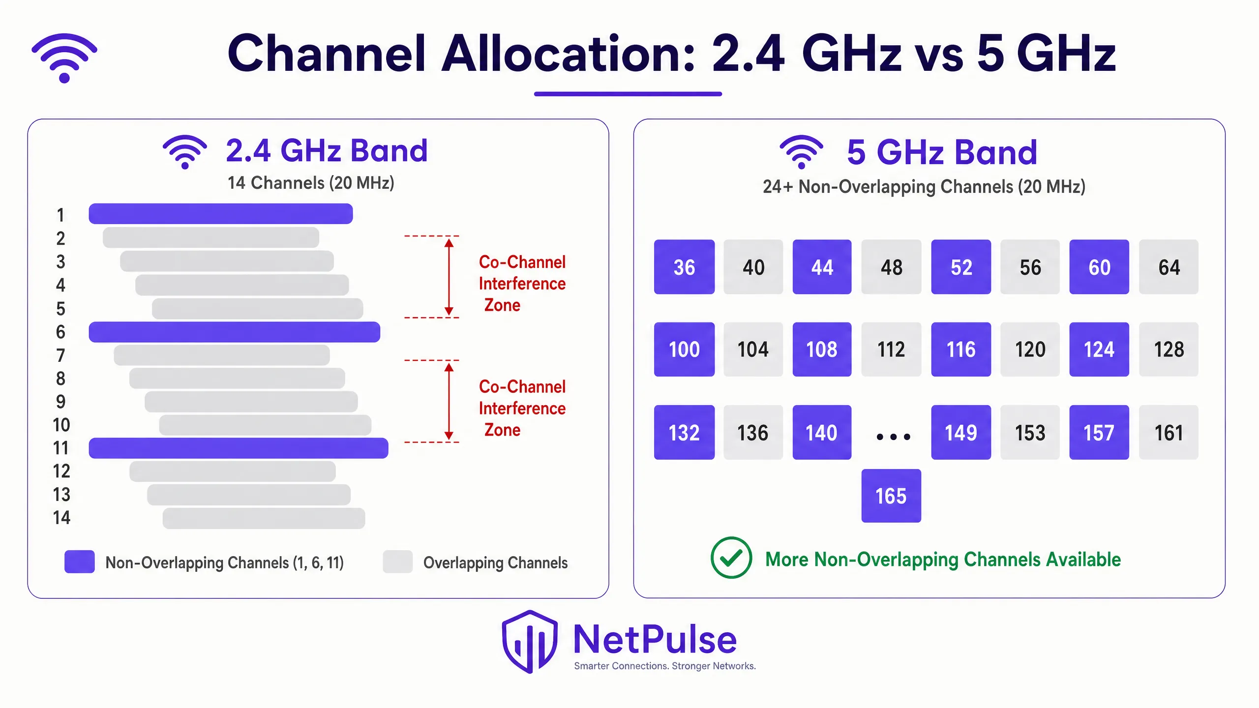
2.4 GHz ব্যান্ড এর সীমিত স্পেকট্রামের কারণে CCI-এর প্রতি অত্যন্ত সংবেদনশীল। বেশিরভাগ রেগুলেটরি ডোমেইনে, 20 MHz চ্যানেল উইডথ ব্যবহার করে মাত্র তিনটি নন-ওভারল্যাপিং চ্যানেল (1, 6, এবং 11) রয়েছে। উচ্চ-ঘনত্বের ডিপ্লয়মেন্টে — যেমন রিটেইল স্টোর ফ্লোর, হোটেল কনফারেন্স উইং বা স্টেডিয়াম কনকোর্স — ওভারল্যাপ সৃষ্টি না করে এই তিনটি চ্যানেল পুনরায় ব্যবহার করা একটি গাণিতিক চ্যালেঞ্জ যা শুধুমাত্র AP প্লেসমেন্টের মাধ্যমে সমাধান করা সম্ভব নয়।
5 GHz ব্যান্ড উল্লেখযোগ্য স্বস্তি প্রদান করে, যা আঞ্চলিক Dynamic Frequency Selection (DFS) রেগুলেশনের উপর নির্ভর করে 24 বা তার বেশি নন-ওভারল্যাপিং 20 MHz চ্যানেল প্রদান করে। যাইহোক, উচ্চতর পিক ডেটা রেট অর্জনের জন্য প্রশস্ত চ্যানেল — 40 MHz, 80 MHz, বা 160 MHz — ব্যবহার করার প্রবণতা প্রায়শই পুনরায় CCI-এর সৃষ্টি করে। 80 MHz চ্যানেল উইডথে, 5 GHz ব্যান্ডের নন-ওভারল্যাপিং চ্যানেলের সংখ্যা 24 থেকে কমে প্রায় ছয়টিতে নেমে আসে। এন্টারপ্রাইজ ডিপ্লয়মেন্টের জন্য, 2.4 GHz-এ 20 MHz চ্যানেল এবং 5 GHz-এ 20 MHz বা 40 MHz চ্যানেল স্ট্যান্ডার্ডাইজ করা চ্যানেল রিইউজ সর্বোচ্চ করতে এবং ইন্টারফারেন্স কমানোর জন্য একটি মৌলিক বেস্ট প্র্যাকটিস। আধুনিক স্পেকট্রাম ব্যবহার সম্পর্কে আরও জানতে, Wi Fi Frequencies: A Guide to Wi-Fi Frequencies in 2026 রিভিউ করুন।
Wi-Fi 6E (IEEE 802.11ax) এবং Wi-Fi 7 (IEEE 802.11be) দ্বারা প্রবর্তিত 6 GHz ব্যান্ড আরও 59টি নন-ওভারল্যাপিং 20 MHz চ্যানেল প্রদান করে, যা উচ্চ-ঘনত্বের ডিপ্লয়মেন্টের জন্য একটি রূপান্তরমূলক সুযোগ। যাইহোক, 6 GHz গ্রহণের জন্য AP এবং ক্লায়েন্ট হার্ডওয়্যার উভয়ের আপগ্রেড প্রয়োজন, যা এটিকে বিদ্যমান ইনফ্রাস্ট্রাকচারের জন্য তাৎক্ষণিক সমাধানের পরিবর্তে একটি মধ্যমেয়াদী বিনিয়োগে পরিণত করে।
ইমপ্লিমেন্টেশন গাইড
ধাপ ১: একটি বিস্তৃত RF সাইট সার্ভে পরিচালনা করুন
কোনো কনফিগারেশন পরিবর্তন করার আগে, একটি বেসলাইন স্থাপন করুন। একটি অ্যাক্টিভ এবং প্যাসিভ RF সাইট সার্ভে অত্যন্ত গুরুত্বপূর্ণ। প্যাসিভ সার্ভে নেটওয়ার্কের সাথে কানেক্ট না করেই বিদ্যমান RF পরিবেশ — সিগন্যাল স্ট্রেন্থ, নয়েজ ফ্লোর, চ্যানেল ইউটিলাইজেশন এবং ইন্টারফারেন্স সোর্স — ক্যাপচার করে। অ্যাক্টিভ সার্ভে প্রকৃত থ্রুপুট এবং রোমিং আচরণ পরিমাপ করে। এটি কোনো এককালীন কাজ নয়; পরিবেশ পরিবর্তিত হয়। হসপিটালিটি ভেন্যুতে অস্থায়ী কাঠামো, রিটেইলে সিজনাল ইনভেন্টরি পরিবর্তন, বা হেলথকেয়ার সেটিংসে নতুন সরঞ্জাম — এগুলো সবই RF প্রোপাগেশনকে উল্লেখযোগ্যভাবে পরিবর্তন করতে পারে।
Ekahau, NetSpot, বা ভেন্ডর-নির্দিষ্ট সার্ভে অ্যাপ্লিকেশনের মতো টুলগুলো ইন্টারফারেন্স জোন, কভারেজ গ্যাপ এবং চ্যানেল কনফ্লিক্ট শনাক্ত করার জন্য প্রয়োজনীয় ভিজ্যুয়ালাইজেশন প্রদান করে। একটি সাইট সার্ভের ফলাফল সরাসরি AP প্লেসমেন্ট, চ্যানেল অ্যাসাইনমেন্ট এবং ট্রান্সমিট পাওয়ার সেটিংস নির্ধারণে সহায়তা করা উচিত।
ধাপ ২: ট্রান্সমিট পাওয়ার (Tx Power) অপ্টিমাইজ করুন
একটি সাধারণ ভুল ধারণা হলো AP ট্রান্সমিট পাওয়ার বাড়ালে কভারেজ উন্নত হয় এবং কানেক্টিভিটি সমস্যার সমাধান হয়। বাস্তবে, এটি CCI-কে আরও বাড়িয়ে তোলে। যদি কোনো AP-এর সিগন্যাল প্রয়োজনের চেয়ে বেশি দূরে পৌঁছায়, তবে এটি পার্শ্ববর্তী সেলগুলোতে ইন্টারফারেন্স তৈরি করে এবং একটি অপ্রতিসম RF পরিবেশ সৃষ্টি করে।
ক্লায়েন্ট সক্ষমতার সাথে মিল রাখা: মোবাইল ডিভাইসগুলো (স্মার্টফোন, ট্যাবলেট) সাধারণত 10–15 dBm-এ ট্রান্সমিট করে। যদি একটি AP 25 dBm-এ ট্রান্সমিট করে, তবে ক্লায়েন্ট AP-কে স্পষ্টভাবে শুনতে পায়, কিন্তু AP ক্লায়েন্টকে শুনতে সংগ্রাম করে — এটি ক্লাসিক হিডেন নোড সমস্যা। এর ফলে রিট্রান্সমিশন ঘটে, কার্যকর থ্রুপুট কমে যায় এবং চ্যানেল ইউটিলাইজেশন বৃদ্ধি পায়।
পাওয়ার টিউনিং গাইডলাইন:
| ব্যান্ড | প্রস্তাবিত Tx Power | যৌক্তিকতা |
|---|---|---|
| 2.4 GHz | 10–14 dBm | স্মার্টফোনের Tx সক্ষমতার সাথে মিল রাখুন; সেলের আকার কমান |
| 5 GHz | 14–17 dBm | উচ্চ ফ্রিকোয়েন্সিতে পাথ লস পূরণের জন্য সামান্য বেশি |
| 6 GHz | 17–20 dBm | উচ্চ পাথ লসের জন্য সামান্য বেশি পাওয়ার প্রয়োজন |
ব্যান্ড স্টিয়ারিংকে উৎসাহিত করতে 2.4 GHz পাওয়ার সাধারণত 5 GHz-এর চেয়ে 3–6 dB কম হওয়া উচিত, যা সক্ষম ক্লায়েন্টদের কম যানজটপূর্ণ 5 GHz ব্যান্ডে পুশ করে।
ধাপ ৩: ডায়নামিক রেডিও ম্যানেজমেন্ট ইমপ্লিমেন্ট করুন
আধুনিক এন্টারপ্রাইজ WLAN কন্ট্রোলারগুলোতে ডায়নামিক রেডিও ম্যানেজমেন্ট অ্যালগরিদম রয়েছে — Cisco-এর Radio Resource Management (RRM), Aruba-এর Adaptive Radio Management (ARM), এবং Juniper Mist, Extreme Networks ও অন্যান্যদের সমতুল্য সিস্টেম। এই সিস্টেমগুলো ক্রমাগত RF পরিবেশ মনিটর করে এবং CCI প্রশমিত করতে ডায়নামিকভাবে চ্যানেল অ্যাসাইনমেন্ট ও ট্রান্সমিট পাওয়ার অ্যাডজাস্ট করে।
যাইহোক, এই সিস্টেমগুলোর সতর্ক টিউনিং প্রয়োজন। স্টেডিয়াম বা ট্রান্সপোর্ট হাবের মতো উচ্চ-ঘনত্বের পরিবেশে সম্পূর্ণভাবে ডিফল্ট অটোমেটেড সেটিংসের উপর নির্ভর করলে প্রায়শই অস্থিতিশীলতা দেখা দেয়। মূল টিউনিং প্যারামিটারগুলোর মধ্যে রয়েছে:
- চ্যানেল চেঞ্জ থ্রেশহোল্ড: চ্যানেল পরিবর্তন ট্রিগার করার জন্য প্রয়োজনীয় ইন্টারফারেন্সের মাত্রা। খুব কম সেট করা হলে, সিস্টেমটি ক্ষণস্থায়ী ইন্টারফারেন্সের (মাইক্রোওয়েভ ওভেন, ব্লুটুথ ডিভাইস) প্রতিক্রিয়ায় ক্রমাগত চ্যানেল পরিবর্তন করে, যার ফলে ক্লায়েন্ট ডিসকানেক্ট হয়।
- পাওয়ার চেঞ্জ ইন্টারভ্যাল: সিস্টেমটি কত ঘন ঘন ট্রান্সমিট পাওয়ার অ্যাডজাস্ট করে। স্থিতিশীল পরিবেশে, কম ঘন ঘন অ্যাডজাস্টমেন্ট ক্লায়েন্টদের ব্যাঘাত কমায়।
- মিনিমাম এবং ম্যাক্সিমাম পাওয়ার বাউন্ডস: হার্ড লিমিট যা অ্যালগরিদমকে আপনার ডিজাইন প্যারামিটারের বাইরে পাওয়ার লেভেল সেট করতে বাধা দেয়。
ধাপ ৪: লিগ্যাসি বেসিক ডেটা রেট ডিজেবল করুন
যদি আপনার 2.4 GHz রেডিওতে এখনও 1, 2, 5.5, এবং 11 Mbps বেসিক (বাধ্যতামূলক) রেট হিসেবে এনাবল করা থাকে, তবে ম্যানেজমেন্ট ফ্রেমগুলো — বীকন, প্রোব রেসপন্স এবং অ্যাকনলেজমেন্ট — এই কম রেটে ট্রান্সমিট হয়। 1 Mbps-এ একটি একক বীকন 11 Mbps-এর একই বীকনের চেয়ে 10 গুণ বেশি এয়ারটাইম খরচ করে। শত শত AP এবং হাজার হাজার ক্লায়েন্ট জুড়ে, এই ওভারহেডটি উল্লেখযোগ্য।
12 Mbps-এর নিচের রেটগুলো ডিজেবল করলে সমস্ত ম্যানেজমেন্ট এবং ডেটা ফ্রেম আরও দক্ষ মডুলেশন ব্যবহার করতে বাধ্য হয়। এটি কার্যকরভাবে AP-এর কভারেজ সেলকেও ছোট করে, কারণ শুধুমাত্র 12 Mbps বা তার চেয়ে ভালো স্পিড পাওয়ার মতো কাছাকাছি থাকা ক্লায়েন্টরাই যুক্ত হতে পারে। এটি প্রতিটি AP-এর CCI ফুটপ্রিন্ট কমানোর জন্য একটি প্রাকৃতিক মেকানিজম তৈরি করে।
ধাপ ৫: সিমলেস রোমিংয়ের জন্য 802.11k/v/r ইমপ্লিমেন্ট করুন
স্টিকি ক্লায়েন্ট — যেসব ডিভাইস কাছাকাছি থাকা AP-তে রোম করতে অস্বীকার করে — তারা CCI-এর একটি প্রধান কারণ। কম ডেটা রেটে দূরবর্তী AP-এর সাথে যুক্ত একটি ক্লায়েন্ট অসামঞ্জস্যপূর্ণ এয়ারটাইম খরচ করে, যা সেই চ্যানেলের অন্যান্য সমস্ত ক্লায়েন্টের পারফরম্যান্স কমিয়ে দেয়।
- 802.11k (Radio Resource Measurement): ক্লায়েন্টদের একটি নেইবার রিপোর্ট প্রদান করে, যা তাদের কাছাকাছি থাকা AP এবং তাদের সিগন্যাল স্ট্রেন্থ সম্পর্কে অবহিত করে।
- 802.11v (BSS Transition Management): নেটওয়ার্ককে ক্লায়েন্টদের কাছে রোমিং সাজেশন পাঠানোর অনুমতি দেয়, কার্যকরভাবে তাদের একটি ভালো AP-তে যাওয়ার জন্য অনুরোধ করে।
- 802.11r (Fast BSS Transition): টার্গেট AP-গুলোর সাথে ক্লায়েন্টদের প্রি-অথেনটিকেট করে রোমিং ল্যাটেন্সি কমায়, যা ভয়েস এবং ভিডিও অ্যাপ্লিকেশনের জন্য অত্যন্ত গুরুত্বপূর্ণ।
এই প্রোটোকলগুলো একসাথে কাজ করে নিশ্চিত করে যে ক্লায়েন্টরা সর্বদা সর্বোত্তম AP-এর সাথে যুক্ত থাকে, যা প্রতি-ক্লায়েন্ট এয়ারটাইম খরচ কমায় এবং CCI প্রশমিত করে।
বেস্ট প্র্যাকটিস
নিম্ন বেসিক ডেটা রেট ডিজেবল করা: লিগ্যাসি ডেটা রেট (1, 2, 5.5, এবং 11 Mbps) ডিজেবল করলে ক্লায়েন্টরা আরও দক্ষ মডুলেশন স্কিম ব্যবহার করতে বাধ্য হয়। এটি ম্যানেজমেন্ট ফ্রেম এবং ডেটা ট্রান্সমিশনের জন্য প্রয়োজনীয় এয়ারটাইম কমায়, কার্যকরভাবে AP-এর কভারেজ সেলকে ছোট করে। এটি যেকোনো আধুনিক এন্টারপ্রাইজ ডিপ্লয়মেন্টের জন্য একটি মৌলিক অপ্টিমাইজেশন, যা Office Wi Fi: Optimize Your Modern Office Wi-Fi Network -এ বিস্তারিত আলোচনা করা হয়েছে।
DFS চ্যানেলগুলোর সদ্ব্যবহার করা: 5 GHz ব্যান্ডে, উপলব্ধ নন-ওভারল্যাপিং স্পেকট্রাম প্রসারিত করতে Dynamic Frequency Selection (DFS) চ্যানেলগুলো (বেশিরভাগ রেগুলেটরি ডোমেইনে 52–144) ব্যবহার করুন। নিশ্চিত করুন যে আপনার AP এবং ক্লায়েন্ট ডিভাইসগুলো DFS সাপোর্ট করে এবং রাডার ইভেন্টগুলো মনিটর করুন যা চ্যানেল পরিবর্তনে বাধ্য করতে পারে। যেসব পরিবেশে রাডার ইভেন্ট ঘন ঘন ঘটে (বিমানবন্দর বা সামরিক স্থাপনার কাছাকাছি), সেখানে নন-DFS চ্যানেলগুলোতে সীমাবদ্ধ রাখার কথা বিবেচনা করুন।
কৌশলগত AP প্লেসমেন্ট: দীর্ঘ হলওয়েতে AP স্থাপন করা এড়িয়ে চলুন যেখানে RF সিগন্যাল বাধাহীনভাবে ছড়িয়ে পড়ে এবং হলওয়ে ইফেক্ট তৈরি করে। এর পরিবর্তে, রুম বা নির্দিষ্ট কভারেজ এরিয়ার মধ্যে AP স্থাপন করুন যেখানে ব্যবহারকারীরা জড়ো হয়। সেলের সীমানা তৈরি করতে ভবনের ভৌত কাঠামো — দেয়াল, মেঝে, র্যাকিং — প্রাকৃতিক RF অ্যাটেনুয়েটর হিসেবে ব্যবহার করুন।
লোকেশন সার্ভিসের জন্য BLE বিবেচনা করা: যদি WiFi-এর পাশাপাশি লোকেশন-ভিত্তিক সার্ভিস ডিপ্লয় করা হয়, তবে বুঝতে হবে কীভাবে Bluetooth Low Energy আপনার ওয়্যারলেস ইনফ্রাস্ট্রাকচারের সাথে ইন্টারঅ্যাক্ট করে। BLE বীকন এবং WiFi রেডিওর মধ্যে ইন্টারফারেন্স এড়াতে বিস্তারিত ইন্টিগ্রেশন কৌশলের জন্য BLE Low Energy Explained for Enterprise দেখুন।
গেস্ট এবং কর্পোরেট ট্রাফিক সেগমেন্ট করা: নিশ্চিত করুন যে VLAN এবং আলাদা SSID ব্যবহার করে কর্পোরেট ইনফ্রাস্ট্রাকচার থেকে Guest WiFi ট্রাফিক সঠিকভাবে সেগমেন্ট করা হয়েছে। প্রতি AP-তে ব্রডকাস্ট করা SSID-এর সংখ্যা কমানো (আদর্শভাবে তিনটির বেশি নয়) ম্যানেজমেন্ট ফ্রেম ওভারহেড কমায় এবং সামগ্রিক চ্যানেল দক্ষতা উন্নত করে।
ট্রাবলশুটিং এবং ঝুঁকি প্রশমন
স্টিকি ক্লায়েন্ট সমস্যা
যেসব ক্লায়েন্ট শক্তিশালী সিগন্যালসহ কাছাকাছি থাকা AP-তে রোম করতে অস্বীকার করে, তারা CCI-তে উল্লেখযোগ্যভাবে অবদান রাখে। একটি স্টিকি ক্লায়েন্ট যত দূরে সরে যায়, তার ডেটা রেট তত কমে যায়, ফলে একই পরিমাণ ডেটা ট্রান্সমিট করতে বেশি এয়ারটাইম খরচ হয়। 802.11k/v এনাবল করার পাশাপাশি, আপনার সেল ওভারল্যাপ শতাংশ রিভিউ করুন। সিমলেস রোমিংয়ের জন্য সেলগুলো প্রায় 15–20% ওভারল্যাপ হওয়া উচিত। অধিক ওভারল্যাপ ক্লায়েন্টদের রোম করার জন্য কম উৎসাহ দেয় যতক্ষণ না সিগন্যালের গুণমান মারাত্মকভাবে কমে যায়।
রগ অ্যাক্সেস পয়েন্ট (Rogue Access Points)
কর্মচারী বা গেস্টদের দ্বারা আনা অননুমোদিত AP — ইথারনেট পোর্টে প্লাগ করা কনজ্যুমার-গ্রেড রাউটার — একটি সতর্কতার সাথে পরিকল্পিত চ্যানেল প্ল্যানকে ধ্বংস করে দিতে পারে। রগ AP শনাক্ত এবং দমন করতে অবিচ্ছিন্ন Wireless Intrusion Prevention Systems (WIPS) ইমপ্লিমেন্ট করুন। নিশ্চিত করুন যে আপনার নেটওয়ার্ক অ্যাক্সেস কন্ট্রোল (NAC) ব্যবস্থা শক্তিশালী, এবং আপনার NAC ইনফ্রাস্ট্রাকচার আধুনিকীকরণের রিসোর্সগুলো রিভিউ করার কথা বিবেচনা করুন: La lista de verificación para migrar de NAC heredado a NAC nativo de la nube অথবা A Lista de Verificação para Migrar de NAC Legado para NAC Nativo da Nuvem ।
নন-WiFi ইন্টারফারেন্স সোর্স
সব ইন্টারফারেন্স অন্যান্য AP থেকে আসে না। মাইক্রোওয়েভ ওভেন, ব্লুটুথ ডিভাইস, বেবি মনিটর এবং DECT ফোন সবই 2.4 GHz ব্যান্ডে কাজ করে। স্পেকট্রাম অ্যানালাইজারগুলো এই নন-802.11 ইন্টারফারেন্স সোর্সগুলো শনাক্ত করতে পারে, যা RRM অ্যালগরিদমগুলো ভুলভাবে WiFi ইন্টারফারেন্স হিসেবে ব্যাখ্যা করতে পারে এবং অনুপযুক্ত প্রতিক্রিয়া দেখাতে পারে। এই সোর্সগুলো শনাক্ত করে তা দূর করা বা স্থানান্তরিত করা প্রায়শই চ্যানেল পরিবর্তনের চেয়ে বেশি কার্যকর।
সাধারণ ফেইলিওর মোড
| ফেইলিওর মোড | মূল কারণ | প্রশমন |
|---|---|---|
| উচ্চ রিট্রাই রেট (>10%) | CCI বা হিডেন নোড | Tx পাওয়ার কমান; চ্যানেল প্ল্যান রিভিউ করুন |
| শক্তিশালী সিগন্যাল থাকা সত্ত্বেও কম থ্রুপুট | প্রতি AP-তে অত্যধিক ক্লায়েন্ট; CCI | AP যোগ করুন; চ্যানেল উইডথ কমান |
| ধ্রুবক চ্যানেল পরিবর্তন | RRM থ্রেশহোল্ড খুব কম | ইন্টারফারেন্স থ্রেশহোল্ড বাড়ান |
| ক্লায়েন্টরা রোম করছে না | 802.11k/v নেই; অত্যধিক সেল ওভারল্যাপ | 802.11k/v এনাবল করুন; Tx পাওয়ার অ্যাডজাস্ট করুন |
| 5 GHz-এ বিরতিহীন ড্রপ | DFS রাডার ইভেন্ট | DFS ইভেন্ট মনিটর করুন; নন-DFS চ্যানেল বিবেচনা করুন |
ROI এবং ব্যবসায়িক প্রভাব
CCI সমাধান করা পরিমাপযোগ্য এবং পরিমাণযোগ্য রিটার্ন প্রদান করে। রিটেইল পরিবেশে, নির্ভরযোগ্য কানেক্টিভিটি নির্বিঘ্ন মোবাইল পয়েন্ট-অফ-সেল ট্রানজ্যাকশন, রিয়েল-টাইম ইনভেন্টরি লুকআপ এবং ডিজিটাল সাইনেজ আপডেট সক্ষম করে। পিক ট্রেডিংয়ের সময় একটি একক POS আউটেজ বিক্রি হারানো এবং অপারেশনাল ব্যাঘাতের কারণে হাজার হাজার পাউন্ড ক্ষতি করতে পারে। হসপিটালিটিতে, নেটওয়ার্ক পারফরম্যান্স সরাসরি TripAdvisor এবং Google-এর মতো প্ল্যাটফর্মগুলোতে গেস্ট রিভিউ স্কোরকে প্রভাবিত করে, যেখানে কানেক্টিভিটি ধারাবাহিকভাবে গেস্ট স্যাটিসফ্যাকশনের শীর্ষ তিনটি ফ্যাক্টরের মধ্যে থাকে。
চ্যানেল ইউটিলাইজেশন, প্রতি AP-তে ক্লায়েন্ট সংখ্যা, রিট্রাই রেট এবং ইন্টারফারেন্স ইভেন্টগুলো ক্রমাগত মনিটর করতে WiFi Analytics ব্যবহার করে, IT টিমগুলো রিঅ্যাক্টিভ ট্রাবলশুটিং থেকে প্রোঅ্যাক্টিভ নেটওয়ার্ক ম্যানেজমেন্টে স্থানান্তরিত হতে পারে। সংশোধনের পরে ট্র্যাক করার জন্য মূল পারফরম্যান্স ইন্ডিকেটরগুলোর (KPI) মধ্যে রয়েছে:
- চ্যানেল ইউটিলাইজেশন: নির্ভরযোগ্য পারফরম্যান্সের জন্য 50%-এর নিচে লক্ষ্য রাখুন; 70%-এর উপরে ক্যাপাসিটি সমস্যা নির্দেশ করে।
- রিট্রাই রেট: 5%-এর নিচে লক্ষ্য রাখুন; 10%-এর উপরে উল্লেখযোগ্য ইন্টারফারেন্স বা কভারেজ সমস্যা নির্দেশ করে।
- অ্যাভারেজ ক্লায়েন্ট থ্রুপুট: উন্নতির পরিমাণ নির্ধারণ করতে পরিবর্তনের আগে এবং পরে বেসলাইন করুন।
- সাপোর্ট টিকিট ভলিউম: সংশোধনের 30 দিনের মধ্যে WiFi-সম্পর্কিত টিকিট পরিমাপযোগ্যভাবে হ্রাস পাওয়া উচিত।
একটি প্রফেশনাল RF সাইট সার্ভে এবং চ্যানেল প্ল্যান সংশোধনে বিনিয়োগ সাধারণত IT সাপোর্ট ওভারহেড হ্রাস এবং উন্নত অপারেশনাল ধারাবাহিকতার মাধ্যমে এক থেকে দুই কোয়ার্টারের মধ্যে ফেরত আসে।
Key Definitions
Co-Channel Interference (CCI)
Interference caused when multiple access points and clients operate on the same frequency channel, forcing them to share airtime via CSMA/CA and wait for the channel to clear before transmitting. CCI scales with the number of APs on the same channel.
The primary cause of degraded performance in dense deployments. Often misdiagnosed as an 'internet speed' or 'bandwidth' issue by end-users and non-technical stakeholders.
Adjacent-Channel Interference (ACI)
Interference caused by overlapping frequency bands — for example, using channels 1 and 3 simultaneously in the 2.4 GHz band. Unlike CCI, ACI is caused by spectral overlap rather than channel sharing.
Easily avoided by adhering strictly to non-overlapping channels (1, 6, 11 in 2.4 GHz). ACI is less common in well-managed enterprise networks but frequently seen in environments with rogue APs.
Carrier Sense Multiple Access with Collision Avoidance (CSMA/CA)
The protocol WiFi uses to manage access to the RF medium. Devices must listen for a clear channel before transmitting, and use random backoff timers to avoid simultaneous transmissions.
Understanding CSMA/CA is fundamental to understanding why CCI destroys throughput. It is a polite, orderly protocol that fails under heavy contention — the more devices sharing a channel, the longer each must wait.
Dynamic Frequency Selection (DFS)
A regulatory mechanism that allows WiFi devices to share spectrum with radar systems in the 5 GHz band. APs must monitor for radar signals and vacate the channel within 10 seconds if detected.
Crucial for enterprise deployments to unlock additional non-overlapping channels in the 5 GHz band. Requires careful monitoring; unexpected DFS events can cause client disconnects if not managed properly.
Hidden Node Problem
Occurs when two client devices can hear the AP but cannot hear each other, leading them to transmit simultaneously and cause collisions at the AP. Results in high retry rates and reduced throughput.
Often caused by APs transmitting at significantly higher power levels than client devices. Mitigated by matching AP Tx power to client Tx capability.
Radio Resource Management (RRM)
Automated systems within enterprise WLAN controllers that dynamically adjust channel assignments and transmit power based on continuous RF monitoring. Examples include Cisco RRM and Aruba ARM.
Useful in dynamic environments but requires careful threshold tuning. Default settings are rarely optimal for high-density venues and can cause instability if too aggressive.
Airtime Fairness
A WLAN feature that allocates equal transmission time to all associated clients, regardless of their data rate. Prevents slower (legacy or distant) clients from monopolising the channel at the expense of faster clients.
Critical in mixed-device environments (e.g., a hotel with both modern smartphones and legacy IoT sensors). Without airtime fairness, a single slow client can halve the effective throughput for all other clients on the channel.
BSS Transition Management (802.11v)
An IEEE 802.11 protocol that allows a WLAN controller to send roaming suggestions to client devices, recommending they associate with a different (closer or less congested) AP.
Part of the 802.11k/v/r suite of roaming protocols. Directly addresses the sticky client problem by giving the network a mechanism to influence client roaming decisions.
Channel Utilisation
The percentage of time a given RF channel is occupied by transmissions (both 802.11 and non-802.11). A key metric for diagnosing CCI.
Target below 50% for reliable performance. Above 70% indicates a capacity problem requiring channel plan remediation or additional AP density with reduced cell sizes.
Worked Examples
A 400-room luxury hotel is experiencing severe connectivity issues in the conference centre during a major tech summit. 800 attendees report slow speeds and frequent disconnects despite dense AP placement. The IT team has already tried rebooting all APs.
Step 1: Conduct an immediate spectrum analysis using a laptop-based tool (Ekahau, Metageek Chanalyzer) to baseline channel utilisation and interference levels. The analysis reveals 2.4 GHz channel utilisation at 94% and significant CCI on 5 GHz due to 80 MHz channel widths across all APs.
Step 2: Disable 2.4 GHz radios on every other AP in the high-density conference area. With 800 devices in a confined space, the 2.4 GHz band is beyond saturation. Reducing the number of competing APs on three channels immediately reduces contention.
Step 3: Reduce 5 GHz channel widths from 80 MHz to 20 MHz across all conference centre APs. This increases available non-overlapping channels from approximately 6 to 24, allowing each AP to operate on a unique channel.
Step 4: Lower AP transmit power to 12 dBm (2.4 GHz) and 15 dBm (5 GHz) to shrink cell sizes and encourage clients to associate with the nearest AP rather than a distant one.
Step 5: Disable basic data rates below 12 Mbps on all radios.
Step 6: Validate with a post-change spectrum analysis. Channel utilisation should drop below 60% and retry rates below 8%.
A national retail chain has deployed APs down the centre of every aisle in a large warehouse-style store. Staff report poor roaming on handheld scanners and persistent connectivity drops near the loading bay.
Step 1: Conduct a passive RF survey to visualise coverage and identify the hallway effect. The survey confirms that APs at opposite ends of 60-metre aisles are on the same channel and interfering with each other.
Step 2: Relocate APs to a staggered deployment pattern, positioning them above the racking rather than in the aisle centre. This uses the metal racking as a natural RF attenuator, creating distinct coverage cells per aisle section.
Step 3: Implement directional antennas (downtilt patch antennas) on specific APs near the loading bay to focus RF energy downward and limit horizontal propagation into adjacent cells.
Step 4: Adjust RRM profiles to react less aggressively to transient interference from loading bay equipment (forklifts, metal doors).
Step 5: Enable 802.11k and 802.11v on the WLAN controller to assist handheld scanner roaming decisions.
Step 6: Validate roaming performance by walking the floor with a handheld scanner and monitoring association events in the WLAN controller.
Practice Questions
Q1. You are designing the WiFi network for a new high-density university lecture hall with 500 seats. The architect insists on hiding all APs above a metal-mesh drop ceiling for aesthetic reasons. The university requires reliable 4K video streaming for remote lectures. How do you address the architectural constraint without compromising RF performance?
Hint: Consider the impact of metal mesh on RF propagation, the resulting requirement for Tx power, and the asymmetric coverage problem this creates.
View model answer
The metal mesh will severely attenuate the RF signal, potentially by 10–20 dB depending on mesh density. To compensate, APs would need to transmit at maximum power, which increases CCI in adjacent spaces and creates a significant hidden node problem for clients trying to transmit back through the mesh. The recommended approach is to negotiate the use of APs with external directional antennas (downtilt patch antennas) mounted below the ceiling tile, with the AP body concealed above the mesh. Alternatively, specify aesthetically designed APs (e.g., Cisco Meraki or Aruba with low-profile enclosures) that can be mounted flush below the ceiling. If the architect is immovable on the metal mesh, specify APs with external antenna ports and route antenna cables through the mesh to below-ceiling mounting points. Under no circumstances should RF design be compromised for aesthetics when 4K streaming reliability is a stated requirement.
Q2. A retail client is upgrading their POS tablets to a new model that only supports 2.4 GHz WiFi. They currently operate a well-managed dual-band network with 30 APs in a medium-sized store. What changes should you make to accommodate the new tablets without degrading overall network performance for other devices?
Hint: Focus on band steering, basic data rates, and the impact of adding 2.4 GHz-only devices to an already constrained band.
View model answer
First, ensure band steering is aggressively enabled to push all capable devices (smartphones, modern laptops) to the 5 GHz band, clearing airtime on 2.4 GHz for the POS tablets. Second, audit the 2.4 GHz channel plan to ensure strict adherence to channels 1, 6, and 11 with no deviations. Third, disable basic data rates below 12 Mbps on the 2.4 GHz band to force the POS tablets to transmit more efficiently, reducing their airtime consumption per transaction. Fourth, consider disabling 2.4 GHz radios on select APs if the density is too high — creating fewer, larger 2.4 GHz cells while maintaining dense 5 GHz coverage. Finally, monitor 2.4 GHz channel utilisation post-deployment and set an alert threshold at 60% to catch degradation before it impacts POS performance.
Q3. After deploying a new WLAN controller, the automated Radio Resource Management feature is constantly changing channels every 15–20 minutes, causing brief disconnects for VoIP users and complaints from the operations team. The IT manager wants to disable RRM entirely. What is your recommendation?
Hint: Consider the trade-off between RRM stability and the long-term benefit of automated channel management in a dynamic environment.
View model answer
Disabling RRM entirely is not recommended. Without automated channel management, the network will gradually degrade as the RF environment changes (new equipment, seasonal changes, rogue APs). The correct approach is to tune the RRM thresholds rather than disable the feature. Increase the interference threshold required to trigger a channel change — the algorithm is currently reacting to transient interference that does not warrant a channel change. Extend the minimum time between channel changes to at least 60 minutes. Consider implementing a scheduled maintenance window for channel changes, restricting automated changes to off-peak hours (e.g., 02:00–04:00). Enable event logging for all RRM-triggered changes to identify the specific interference source causing the frequent triggers. Once the root cause is identified (often a non-WiFi interference source like a microwave or DECT phone), address it directly.
Continue reading in this series
Understanding RSSI and Signal Strength for Optimal Channel Planning
This guide provides a comprehensive technical deep-dive into RSSI, Signal-to-Noise Ratio (SNR), and RF propagation principles for optimal channel planning. It equips IT managers, network architects, and venue operations directors with actionable strategies to mitigate Co-Channel and Adjacent Channel Interference, optimise AP placement, and leverage analytics for measurable business impact across hospitality, retail, and public-sector environments.
20MHz vs 40MHz vs 80MHz: Which Channel Width Should You Use?
This guide provides a definitive, vendor-neutral technical reference for IT managers, network architects, and venue operations directors on selecting the correct WiFi channel width — 20MHz, 40MHz, or 80MHz — across enterprise deployments in hospitality, retail, events, and public-sector environments. It covers the underlying IEEE 802.11 mechanics, real-world capacity trade-offs, and step-by-step deployment guidance to help teams make the right call this quarter. Understanding channel width selection is one of the highest-leverage decisions in any wireless LAN design, directly impacting throughput, interference, client density support, and the reliability of guest-facing services.