Compreendendo RSSI e Força do Sinal para Planejamento Ótimo de Canais
Este guia oferece uma análise técnica aprofundada e abrangente sobre RSSI, Relação Sinal-Ruído (SNR) e princípios de propagação de RF para um planejamento de canais ideal. Ele capacita gerentes de TI, arquitetos de rede e diretores de operações de locais com estratégias acionáveis para mitigar Interferência Co-Canal e de Canal Adjacente, otimizar o posicionamento de APs e aproveitar a análise de dados para um impacto comercial mensurável em ambientes de hospitalidade, varejo e setor público.
Ouça este guia
Ver transcrição do podcast
Resumo Executivo
Para CTOs e arquitetos de rede que supervisionam locais de alta densidade — seja em Hospitalidade , Varejo ou grandes espaços públicos — a implantação de uma infraestrutura sem fio robusta é fundamental para a eficiência operacional e a satisfação dos hóspedes. Este guia técnico explora o que é RSSI e como ele funciona como uma métrica crítica para o planejamento ideal de canais. Ao ir além dos mapas de cobertura básicos e compreender as nuances da propagação de RF, Interferência Co-Canal (CCI) e Interferência de Canal Adjacente (ACI), os líderes de TI podem projetar redes que suportam aplicações de alta taxa de transferência e baixa latência em escala. Examinamos como os limiares precisos de RSSI impulsionam as decisões de roaming, como a largura do canal impacta a eficiência espectral e como o aproveitamento de plataformas avançadas de WiFi Analytics pode mitigar riscos e entregar ROI mensurável. O guia abrange protocolos de roaming IEEE 802.11k/v/r, otimização de SNR, estratégia de posicionamento de AP e cenários de implantação do mundo real em ambientes de hospitalidade e varejo.
Análise Técnica Aprofundada
O que é RSSI? Definição e Medição
O Indicador de Força do Sinal Recebido (RSSI) é uma medição relativa do nível de potência de um sinal de RF recebido por um dispositivo cliente. Medido em decibéis em relação a um miliwatt (dBm), o RSSI é expresso como um valor negativo — quanto mais próximo de zero, mais forte o sinal. Um valor de -30 dBm representa um sinal excepcionalmente forte (geralmente alcançável apenas a um metro do AP), enquanto -90 dBm está no limiar de usabilidade. A tabela a seguir fornece uma referência prática para os limiares de RSSI e sua adequação às aplicações correspondentes:
| RSSI (dBm) | Qualidade do Sinal | Aplicações Adequadas |
|---|---|---|
| -30 a -50 | Excelente | Todas as aplicações, incluindo streaming 4K e VoWiFi de alta densidade |
| -51 a -65 | Boa | Dados de alta taxa de transferência, VoWiFi, análise de localização |
| -66 a -70 | Razoável | Dados padrão, navegação na web, e-mail |
| -71 a -80 | Fraca | Apenas conectividade básica; VoWiFi não confiável |
| Abaixo de -80 | Inutilizável | Desconexões frequentes; não adequado para implantação empresarial |
RSSI vs. Relação Sinal-Ruído (SNR)
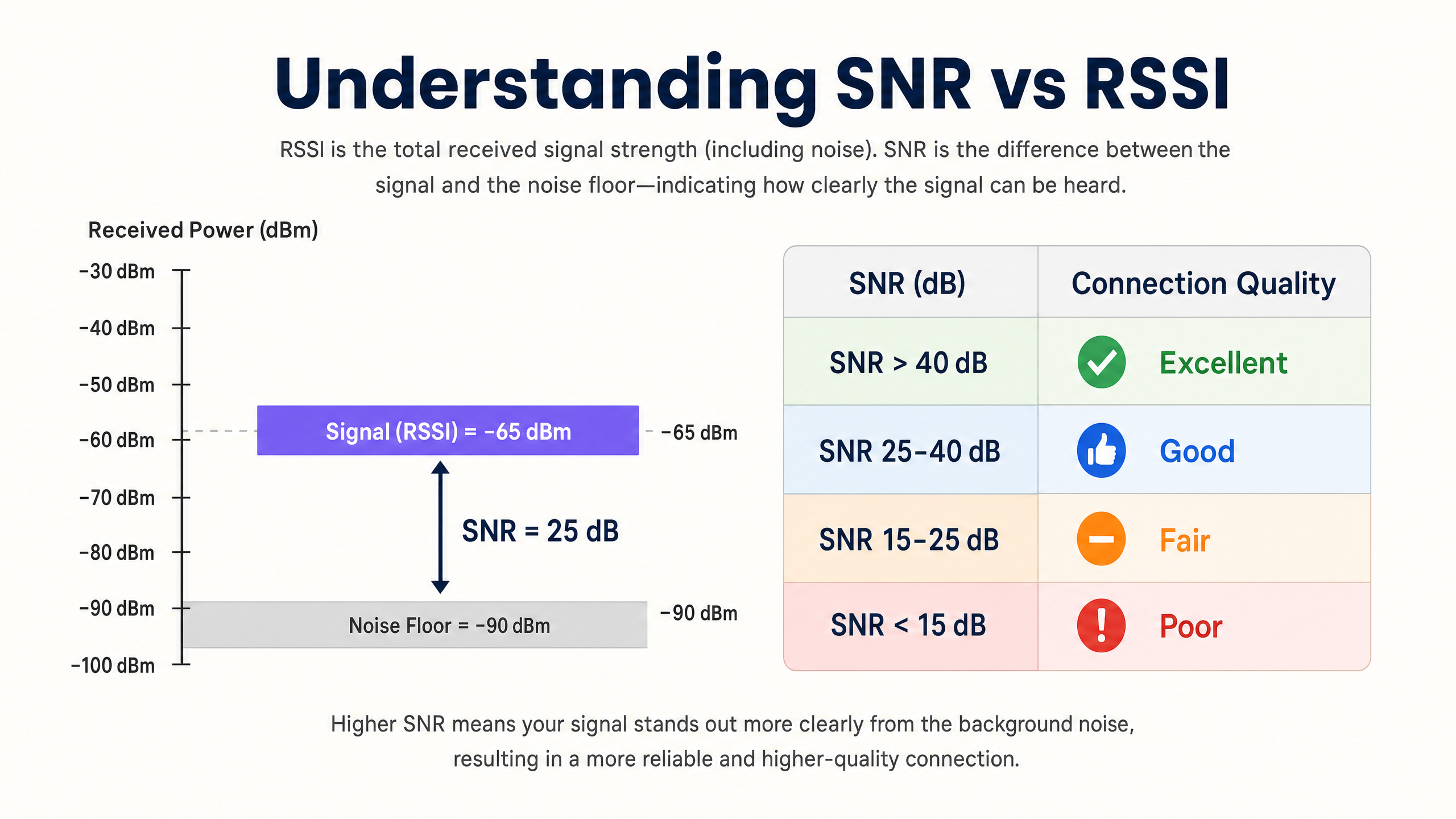
O RSSI por si só é insuficiente para avaliar a qualidade da rede. A Relação Sinal-Ruído (SNR) fornece uma imagem mais precisa da qualidade do link, comparando a força do sinal recebido com o ruído de fundo ambiente. Um SNR de 25 dB ou superior é tipicamente necessário para esquemas de modulação de alta taxa de transferência, como 256-QAM em 802.11ac/ax. Se o ruído de fundo for -90 dBm e o RSSI for -65 dBm, o SNR é de 25 dB — o limiar mínimo para uma operação confiável de alto desempenho.
A implicação prática é significativa: uma rede pode exibir excelentes valores de RSSI em um mapa de calor de cobertura, mas ter um desempenho ruim porque o ruído de fundo é elevado por fontes de interferência não-Wi-Fi (fornos de micro-ondas, telefones DECT, dispositivos Bluetooth ou equipamentos industriais). Sempre instrumente tanto o RSSI quanto o SNR durante levantamentos de site e monitoramento contínuo.
A Física da Propagação e Atenuação de RF
Em ambientes complexos, como hospitais ( Saúde ) ou centros de transporte ( Transporte ), os sinais de RF sofrem atenuação ao passar por obstáculos físicos. Os arquitetos de rede devem considerar essas perdas específicas de material ao realizar levantamentos de site preditivos e definir limites de célula:
| Material | Atenuação Típica (dB) |
|---|---|
| Drywall / Gesso Acartonado | 3–4 dB |
| Vidro (padrão) | 2–3 dB |
| Tijolo | 8–12 dB |
| Concreto | 12–15 dB |
| Concreto Armado / Aço | 15–25+ dB |
| Prateleiras de Metal (varejo) | 10–20 dB |
A natureza logarítmica da escala de decibéis é crucial para internalizar: uma perda de 3 dB reduz a potência do sinal pela metade, enquanto uma perda de 10 dB a reduz por um fator de dez. Um sinal que passa por duas paredes de tijolo (aproximadamente 20 dB de atenuação) é, portanto, 100 vezes mais fraco que o sinal transmitido.
Planejamento de Canais: CCI e ACI
O planejamento ideal de canais requer a mitigação de dois tipos distintos de interferência. A Interferência Co-Canal (CCI) ocorre quando pontos de acesso operando no mesmo canal podem "ouvir" uns aos outros, levando à contenção de meio e ao aumento da latência devido ao protocolo CSMA/CA (Carrier-Sense Multiple Access with Collision Avoidance). Cada dispositivo no canal deve esperar a sua vez, e quando múltiplos APs estão em contenção simultaneamente, a utilização do canal dispara mesmo sob carga moderada de clientes.
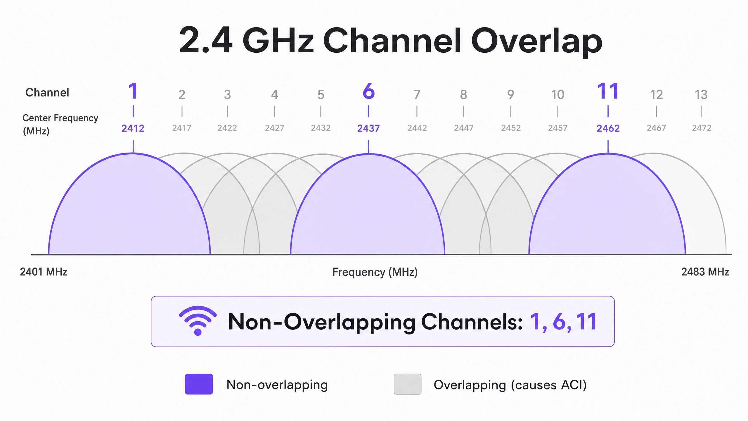
A Interferência de Canal Adjacente (ACI) ocorre quando os APs operam em canais sobrepostos, elevando o ruído de fundo e degradando o SNR. Na banda de 2.4 GHz, apenas os canais 1, 6 e 11 não se sobrepõem. Qualquer outra atribuição de canal causará ACI com um ou ambos os seus vizinhos. Na banda de 5 GHz, a utilização de canais Dynamic Frequency Selection (DFS) expande o espectro disponível, embora eventos de detecção de radar possam forçar mudanças de canal, causando breves interrupções de conectividade.
Ao decidir sobre as larguras de canal, consulte 20MHz vs 40MHz vs 80MHz: Qual Largura de Canal Você Deve Usar? (ou a versão em italiano: 20MHz vs 40MHz vs 80MHz: Quale larghezza di canale dovresti usare? ). O princípio fundamental: canais mais amplos oferecem maior taxa de transferência teórica, mas reduzem o número de opções não sobrepostas, aumentando a CCI em implantações densas.
Guia de Implementação
Passo 1: Defina os Requisitos e Identifique o Dispositivo LCMI
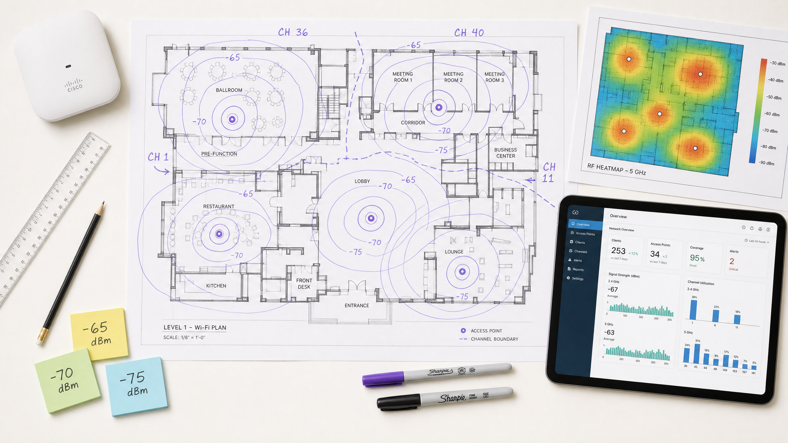
Antes de implantar o hardware, defina a Área de Cobertura Primária (PCA) e a Área de Cobertura Secundária (SCA). Criticamente, identifique o Dispositivo Menos Capaz, Mais Importante (LCMI) — o dispositivo com o rádio mais fraco que deve operar de forma absolutamente confiável. Frequentemente, trata-se de um scanner portátil legado em um armazém, um modelo específico de dispositivo médico em um hospital, ou um smartphone mais antigo em um ambiente de hospitalidade. Projete toda a arquitetura de RF para atender aos requisitos mínimos de RSSI desse dispositivo, e todo o resto terá um desempenho melhor.
Passo 2: Conduza um Levantamento de Campo Ativo
Execute um levantamento de campo ativo para medir RSSI e SNR no mundo real — não apenas um levantamento preditivo usando software. Use ferramentas de análise de espectro para identificar fontes de interferência não-Wi-Fi. Garanta que a cobertura primária atenda ao limiar de -65 dBm e a cobertura secundária (para zonas de sobreposição de roaming) atenda a -70 dBm. Documente o piso de ruído em todas as áreas, pois isso determinará o SNR alcançável e as taxas de dados máximas suportadas.
Passo 3: Posicionamento de AP e Ajuste de Potência
Evite a falácia de que "mais alto é melhor". Definir a potência de transmissão do AP muito alta cria links assimétricos onde o cliente pode ouvir o AP claramente, mas o AP não consegue receber de forma confiável as transmissões mais fracas do cliente. Esta é a causa raiz do problema de cliente pegajoso — dispositivos que permanecem associados a um AP distante, apesar de estarem fisicamente mais próximos de outro. Ajuste a potência de transmissão do AP para 10–14 dBm para corresponder às capacidades do cliente, e garanta uma sobreposição de célula de 15–20% para facilitar o roaming contínuo conforme IEEE 802.11k/v/r.
Passo 4: Imponha Taxas de Dados Mínimas Obrigatórias
Desative as taxas de dados legadas (1, 2, 5.5 e 11 Mbps em 2.4 GHz; 6 e 9 Mbps em 5 GHz). Isso eleva o limiar mínimo de RSSI no qual um cliente considera a conexão aceitável, forçando decisões de roaming mais cedo e impedindo que clientes de baixa taxa consumam tempo de ar desproporcional.
Passo 5: Integre Guest WiFi e Análise
A implantação de uma solução empresarial de Guest WiFi requer autenticação contínua que não degrade a experiência do usuário. Implemente 802.1X para dispositivos corporativos e captive portals seguros para convidados, com WPA3 onde a compatibilidade do dispositivo permitir. Abordagens modernas como How a wi fi assistant Enables Passwordless Access in 2026 reduzem o atrito de integração, mantendo a conformidade com os requisitos PCI DSS e GDPR. A arquitetura de RF descrita neste guia é o pré-requisito para análises e serviços de localização confiáveis — se a RF for mal projetada, os dados serão imprecisos.
Melhores Práticas
Projete para capacidade, não cobertura. Em ambientes modernos de alta densidade, a restrição quase nunca é o alcance do sinal — é a contenção de tempo de ar. Implante mais APs com menor potência de transmissão em vez de menos APs com alta potência. Isso reduz a CCI, melhora o SNR, e aumenta o número de clientes que podem ser atendidos simultaneamente.
Padronize as larguras de canal por ambiente. Padrão de 20 MHz em 2.4 GHz universalmente. Em 5 GHz, use 20 MHz em ambientes de altíssima densidade (estádios, salas de conferência) e 40 MHz em ambientes de densidade moderada (hotéis, varejo). Reserve 80 MHz apenas para cenários de baixa densidade e alta taxa de transferência.
Implemente a pilha de protocolo de roaming. Habilite 802.11k (Medição de Recursos de Rádio), 802.11v (Gerenciamento de Transição BSS), e 802.11r (Transição Rápida BSS) em todos os APs. Isso garante que as decisões de roaming sejam impulsionadas pelas condições de RF, em vez da inércia do cliente, e reduz a latência de reautenticação de centenas de milissegundos para menos de 50 ms.
Valide manualmente os canais atribuídos automaticamente. A maioria dos fornecedores de APs empresariais oferece Gerenciamento Automático de Recursos de Rádio (RRM). Embora útil como linha de base, o RRM pode tomar decisões subótimas em ambientes complexos. Sempre audite o plano de canais pós-implantação e substitua onde for necessário.
Monitore continuamente, não apenas na implantação. Os ambientes de RF mudam com o tempo — novas fontes de interferência aparecem, os padrões de ocupação mudam e as atualizações de firmware alteram o comportamento do rádio. Utilize uma plataforma de WiFi Analytics com monitoramento contínuo de RF para detectar degradação antes que afete os usuários.
Para estratégias mais amplas sobre como alavancar a infraestrutura de rede para resultados de negócios, consulte How To Improve Guest Satisfaction: The Ultimate Playbook .
Solução de Problemas e Mitigação de Riscos
O Problema do Cliente Pegajoso
Sintoma: Dispositivos permanecem conectados a um AP distante com RSSI fraco (-80 dBm) apesar de estarem fisicamente mais próximos de um AP diferente com um sinal forte.
Causa Raiz: A potência de transmissão do AP é muito alta, criando um link assimétrico. O cliente ouve bem o AP e não inicia um roam. Alternativamente, os protocolos 802.11k/v estão desabilitados, deixando o cliente sem orientação sobre APs melhores disponíveis.
Mitigação: Reduza a potência de transmissão do AP para 10–12 dBm. Habilite 802.11k/v/r. Defina taxas de dados mínimas obrigatórias para forçar os clientes a fazer roaming quando o RSSI degrada abaixo do limiar da taxa mínima.
Alta Interferência Co-Canal
Sintoma: Utilização do canal consistentemente acima de 40–50% mesmo sob carga moderada de clientes, resultando em latência elevada e baixa taxa de transferência.
Causa Raiz: APs no mesmo canal são colocados muito próximos uns dos outros, ou as larguras de canal são muito amplas para a densidade da implantação.
Mitigação: Reduza a largura do canal para 20 MHz. Audite o plano de canais para maximizar a separação física entre APs no mesmo canal. Em 2.4 GHz, considere desativar o rádio em cada AP alternado em implantações muito densas.
Piso de Ruído Elevado
Sintoma: Os valores de RSSI parecem aceitáveis nos mapas de calor, mas a taxa de transferência é baixa e as conexões são instáveis.
Causa Raiz: Fontes de interferência não-Wi-Fi (fornos de micro-ondas, telefones DECT, equipamentos industriais, Bluetooth) estão elevando o piso de ruído, degradando o SNR abaixo do limiar necessário para modulação de alta ordem.
Mitigação: Use um analisador de espectro para identificar e caracterizar as fontes de interferência. Migre os clientes afetados para 5 GHz sempre que possível, pois a maioria das interferências não-Wi-Fi está concentrada em 2.4 GHz. Se as fontes de interferência não puderem ser eliminadas, aumente a densidade de APs para melhorar o RSSI e, assim, manter um SNR adequado, apesar do piso de ruído elevado.
À medida que as redes se expandem para espaços municipais e públicos, o planejamento estratégico torna-se cada vez mais crítico. Para obter insights sobre implantações no setor público, leia sobre como Purple Appoints Iain Fox as VP Growth – Public Sector to Drive Digital Inclusion and Smart City Innovation .
ROI e Impacto nos Negócios
A otimização do RSSI e do planejamento de canais impacta diretamente o resultado final em múltiplas dimensões. A tabela a seguir resume os principais resultados de negócios associados a uma rede sem fio bem arquitetada:
| Resultado de Negócio | Mecanismo | Impacto Típico |
|---|---|---|
| Custos de suporte de TI reduzidos | Menos reclamações de conectividade; menos visitas ao local | Redução de 20–40% nos tickets de suporte relacionados ao Wi-Fi |
| Satisfação do hóspede aprimorada | Conectividade confiável e de alta velocidade em todo o local | Melhoria mensurável no NPS e nas pontuações de avaliação |
| Análise de localização precisa | Densidade de AP e SNR suficientes para trilateração confiável | Precisão de localização de menos de 3 metros para análise de fluxo de pessoas |
| Captura de dados primários | Desempenho confiável do captive portal | Taxas de conclusão mais altas no onboarding de Wi-Fi para hóspedes |
| Eficiência operacional | Conectividade confiável para dispositivos portáteis, sistemas POS, IoT | Redução de falhas de transação e tempo de inatividade operacional |
Para os operadores de locais, o Wi-Fi confiável não é mais um centro de custo, mas um facilitador de receita. Ao garantir força de sinal consistente e alto SNR, os locais podem implantar com confiança captive portals para capturar dados primários, impulsionando campanhas de marketing personalizadas e aumentando o valor vitalício do cliente. O investimento em um design de RF adequado gera ROI mensurável por meio da eficiência operacional, engajamento digital aprimorado e a capacidade de implantar análises avançadas e serviços de localização com confiança.
A plataforma agnóstica de hardware da Purple se integra à infraestrutura existente para fornecer a camada de análise sobre uma base de RF bem projetada — transformando dados de força de sinal em inteligência de negócios acionável em ambientes de Hospitalidade , Varejo , Saúde e Transporte .
Definições principais
RSSI (Received Signal Strength Indicator)
A relative measurement of the power level of an RF signal received by a client device, expressed in negative dBm. The closer to zero, the stronger the signal.
Used to determine coverage boundaries, trigger roaming decisions, and assess basic signal availability. Not sufficient on its own to evaluate link quality.
SNR (Signal-to-Noise Ratio)
The difference in decibels (dB) between the received signal strength and the ambient noise floor. Calculated as: SNR (dB) = RSSI (dBm) − Noise Floor (dBm).
The primary determinant of achievable modulation scheme and data rate. An SNR of 25 dB is the minimum for 256-QAM (high-throughput) operation. Always measure alongside RSSI.
CCI (Co-Channel Interference)
Interference that occurs when multiple APs and clients operate on the same channel and can detect each other's transmissions, causing medium contention under the CSMA/CA protocol.
The most common cause of high channel utilisation and latency in enterprise deployments. Mitigated by proper channel planning, power tuning, and ensuring adequate physical separation between APs on the same channel.
ACI (Adjacent Channel Interference)
Interference caused by RF energy from one channel bleeding into an adjacent overlapping channel, raising the noise floor and degrading SNR.
Caused by using overlapping channels in the 2.4 GHz band (anything other than 1, 6, 11). Avoided by strict adherence to non-overlapping channel assignments.
DFS (Dynamic Frequency Selection)
A regulatory mechanism that allows Wi-Fi devices to share the 5 GHz spectrum with radar systems by monitoring for radar signals and vacating the channel if detected.
Expands the available 5 GHz channel set, but requires APs to change channels upon radar detection, causing a brief connectivity disruption. Must be accounted for in deployments near airports, military installations, or weather radar sites.
CSMA/CA (Carrier-Sense Multiple Access with Collision Avoidance)
The medium access protocol used by Wi-Fi, in which devices listen to the RF channel before transmitting and defer if the channel is busy.
The fundamental reason Wi-Fi is a half-duplex, shared medium. CCI forces multiple APs and clients to contend for the same channel, which is why channel planning is critical to performance.
Sticky Client
A client device that remains associated with an AP delivering a weak signal despite being physically closer to a different AP with a stronger signal.
Caused by asymmetric link budgets (AP transmit power too high) or absence of 802.11k/v roaming protocols. Results in poor throughput, high latency, and degraded user experience.
LCMI (Least Capable, Most Important) Device
The device in a deployment with the weakest radio capabilities that is nonetheless critical to business operations.
Used as the design baseline for RF architecture. Designing to meet the LCMI device's requirements ensures all other devices perform adequately.
802.11k/v/r
A suite of IEEE 802.11 amendments: 802.11k (Radio Resource Measurement), 802.11v (BSS Transition Management), and 802.11r (Fast BSS Transition).
Together, these protocols enable intelligent, low-latency client roaming. 802.11k provides neighbour reports, 802.11v enables network-directed roaming, and 802.11r reduces re-authentication time to under 50 ms.
Exemplos práticos
A 300-room hotel is experiencing poor Wi-Fi performance in guest rooms despite having an AP in every corridor. Guests report dropped connections and slow speeds, particularly in rooms furthest from the corridor APs. The existing APs are configured at maximum transmit power (23 dBm) on auto channel assignment.
The root cause is a combination of Co-Channel Interference (CCI) from corridor APs hearing each other down the long hallways, signal attenuation through guest room doors and walls, and the sticky client problem caused by excessively high transmit power. The recommended solution is to transition to an in-room AP deployment model using wall-plate APs (e.g., Cisco Catalyst 9105AXW or Aruba AP-303H). Configure each AP with a transmit power of 10–12 dBm. Disable 2.4 GHz on every other AP in the corridor to reduce CCI. Standardise on 20 MHz channels in 5 GHz with a manual channel plan assigning channels 36, 40, 44, 48, 52, 56, 60, 64 in a repeating pattern. Enable 802.11k/v/r on all APs. Set minimum mandatory data rates to 12 Mbps in 2.4 GHz and 24 Mbps in 5 GHz. Validate with a post-deployment active site survey targeting -65 dBm RSSI and 25 dB SNR in all guest rooms.
A large retail chain operating 50,000 sq ft stores wants to deploy Wi-Fi location analytics to track customer footfall and dwell time by department. Initial data from the existing network shows location accuracy of ±15 metres, which is insufficient for department-level analysis. The existing infrastructure has APs mounted at 6-metre intervals along the central spine of the store.
Location analytics based on RSSI trilateration require a minimum of three APs to hear a client device simultaneously, with each AP receiving a signal of -75 dBm or better. The current linear AP layout means that in the outer departments, clients are only within range of one or two APs, making accurate trilateration impossible. The solution requires a redesigned AP layout using a staggered grid pattern with APs at the perimeter and interior of each department zone, ensuring that any point on the floor is within -75 dBm range of at least three APs. Reduce AP transmit power to 10 dBm to tighten RF cells and improve the differential between AP readings (which is what drives location accuracy). Enable 802.11k/v to ensure devices don't stick to distant APs, which skews location data. Integrate the AP infrastructure with Purple's WiFi Analytics platform to process RSSI data into footfall heatmaps and dwell time reports by department.
Questões práticas
Q1. You are designing a Wi-Fi network for a 40,000-seat stadium. The venue operator wants maximum throughput for concurrent video streaming and social media uploads during events. You are considering using 80 MHz channels in the 5 GHz band to maximise per-client throughput. Is this the recommended approach, and what channel plan would you implement instead?
Dica: Consider the number of non-overlapping 80 MHz channels available in the 5 GHz band versus 20 MHz channels, and the impact of Co-Channel Interference in an open, high-density environment.
Ver resposta modelo
No. Using 80 MHz channels in a stadium is strongly contraindicated. In the standard 5 GHz UNII-1/2/2e bands, there are only a handful of non-overlapping 80 MHz channels, meaning that with the AP density required for 40,000 concurrent users, severe CCI is inevitable. The correct approach is to use 20 MHz channels throughout, which provides up to 24 non-overlapping channels in 5 GHz (including DFS), maximising channel reuse. Directional sector antennas should be used to tightly control RF cell coverage, pointing down into seating sections rather than radiating omnidirectionally. AP density should be calculated based on a target of no more than 30–50 clients per AP radio, with transmit power tuned to match the coverage area of each sector.
Q2. A warehouse deployment uses handheld barcode scanners that frequently drop connections when operators move between aisles. The APs are configured at maximum transmit power (23 dBm) to ensure full coverage. The scanners run a legacy WMS application that requires sub-100ms latency. What is the likely cause and what steps would you take to resolve it?
Dica: Consider the transmit power capabilities of a small handheld scanner versus an enterprise AP, and the implications for the link budget in both directions.
Ver resposta modelo
The likely cause is the sticky client problem resulting from an asymmetric link budget. The APs are transmitting at 23 dBm, so the scanners hear them well across the entire warehouse and do not initiate a roam. However, the scanners' internal radios typically transmit at only 15–17 dBm, meaning the AP cannot reliably receive the scanner's transmissions when it is far away. The solution is to lower AP transmit power to 10–12 dBm to match the scanners' capabilities, ensuring that the coverage cells are appropriately sized and that scanners roam when they move out of range. Enable 802.11k/v/r to facilitate fast roaming. Set minimum mandatory data rates to 12 Mbps to force earlier roaming decisions. Validate with an active site survey using the actual scanner hardware to confirm -65 dBm RSSI and 25 dB SNR throughout all aisles.
Q3. During a site survey for a new hospital wing, you measure an RSSI of -58 dBm from the primary AP throughout the target area. However, the noise floor measured by a spectrum analyser is consistently -72 dBm due to legacy medical monitoring equipment operating in the 2.4 GHz band. The hospital requires reliable VoWiFi for clinical communications. Will this network support VoWiFi, and what actions would you recommend?
Dica: Calculate the SNR and evaluate it against the minimum requirement for VoWiFi. Consider which frequency band is affected and what mitigation options are available.
Ver resposta modelo
No, this network will not reliably support VoWiFi in its current state. The SNR is calculated as -58 dBm - (-72 dBm) = 14 dB. This falls below the minimum 20 dB SNR required for VoWiFi and well below the 25 dB target for high-quality voice. Despite the strong RSSI of -58 dBm, the elevated noise floor from the medical equipment degrades the link quality to an unacceptable level. Recommended actions: First, migrate VoWiFi traffic to the 5 GHz band, which is largely unaffected by the legacy 2.4 GHz medical equipment. Second, increase AP density in the affected areas to improve RSSI to -50 dBm or better, which would yield an SNR of 22 dB even with the elevated noise floor — marginally acceptable for VoWiFi. Third, engage the biomedical engineering team to assess whether the legacy equipment can be replaced or shielded. Fourth, implement QoS (WMM) with voice traffic prioritisation to protect VoWiFi traffic from competing with data traffic during periods of congestion.