Cómo analizar y cambiar tu canal de WiFi para obtener la máxima velocidad
Esta guía de referencia técnica autorizada dota a los responsables de TI y arquitectos de red de las metodologías necesarias para analizar entornos de RF e implementar planes de canales de WiFi óptimos. Proporciona marcos de trabajo prácticos para mitigar la interferencia de cocanal, maximizar el rendimiento y garantizar una conectividad sólida en despliegues empresariales de alta densidad.
Escuchar esta guía
Ver transcripción del podcast
कार्यकारी सारांश
उच्च-घनत्व वाले एंटरप्राइज़ वातावरणों में—चाहे वह 500 कमरों का होटल हो, बहु-मंजिला रिटेल एस्टेट हो, या सार्वजनिक-क्षेत्र का परिसर हो—वायरलेस प्रदर्शन अब केवल एक अतिरिक्त सुविधा नहीं है; यह एक महत्वपूर्ण परिचालन बुनियादी ढांचा (operational infrastructure) है। फिर भी, कई डिप्लॉयमेंट कम थ्रूपुट, उच्च पुनः प्रयास दरों (retry rates) और रुक-रुक कर होने वाली कनेक्टिविटी समस्याओं से जूझते हैं, जो एक ही सुधारने योग्य मूल कारण से उत्पन्न होती हैं: सबऑप्टिमल (अनुपयुक्त) चैनल प्लानिंग। जटिल RF वातावरणों में डिफ़ॉल्ट वेंडर कॉन्फ़िगरेशन या सरल ऑटो-चैनल एल्गोरिदम पर भरोसा करने से अनिवार्य रूप से को-चैनल हस्तक्षेप (co-channel interference) और स्पेक्ट्रम कंजेशन होता है।
यह तकनीकी संदर्भ मार्गदर्शिका आपके वर्तमान RF वातावरण का विश्लेषण करने और एक निश्चित चैनल योजना को लागू करने के लिए वेंडर-न्यूट्रल, इंजीनियरिंग-आधारित कार्यप्रणाली प्रदान करती है। हम 2.4 GHz, 5 GHz और 6 GHz बैंड के परिचालन भौतिकी की जांच करेंगे, स्पेक्ट्रम विश्लेषण के लिए एक संरचित दृष्टिकोण की रूपरेखा तैयार करेंगे, और हस्तक्षेप को कम करने के लिए व्यावहारिक रूपरेखा प्रदान करेंगे। चैनल ऑप्टिमाइज़ेशन को एक बार के डिप्लॉयमेंट कार्य के बजाय एक निरंतर परिचालन अनुशासन मानकर, नेटवर्क टीमें थ्रूपुट में मापने योग्य सुधार कर सकती हैं, सपोर्ट टिकटों की संख्या को कम कर सकती हैं, और अतिथि उपकरणों और महत्वपूर्ण परिचालन बुनियादी ढांचे दोनों के लिए विश्वसनीय कनेक्टिविटी सुनिश्चित कर सकती हैं।
तकनीकी गहन विश्लेषण: RF स्पेक्ट्रम को समझना
चैनल आवंटन के बारे में सूचित निर्णय लेने के लिए, नेटवर्क आर्किटेक्ट्स को 802.11 मानकों के अंतर्निहित तंत्र और भौतिक वातावरण में विभिन्न फ्रीक्वेंसी बैंड कैसे व्यवहार करते हैं, इसे समझना चाहिए।
2.4 GHz बैंड: कमी का प्रबंधन
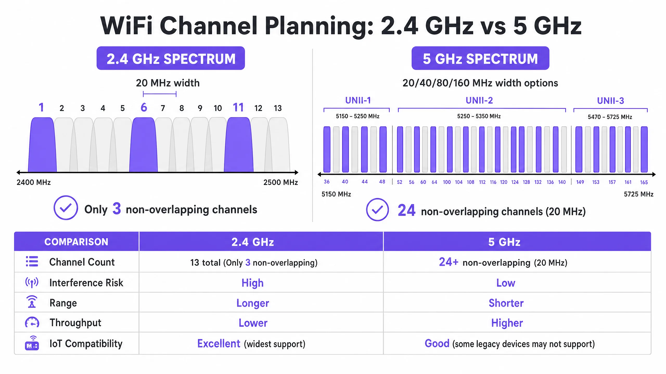
2.4 GHz बैंड बिना लाइसेंस वाले स्पेक्ट्रम का सबसे व्यस्त हिस्सा है। हालांकि यह बेहतर प्रसार विशेषताएं प्रदान करता है—जिससे सिग्नल उच्च फ्रीक्वेंसी की तुलना में दीवारों और फर्शों को अधिक प्रभावी ढंग से पार कर पाते हैं—इसकी चैनल संरचना मौलिक रूप से सीमित है। अधिकांश नियामक क्षेत्रों (यूरोप और उत्तरी अमेरिका सहित) में, यह बैंड ऐसे चैनल प्रदान करता है जो 20 MHz चौड़े हैं लेकिन केवल 5 MHz की दूरी पर हैं।
यह गणित यह तय करता है कि केवल तीन नॉन-ओवरलैपिंग चैनल उपलब्ध हैं: 1, 6, और 11। कोई भी डिप्लॉयमेंट जो इस तिकड़ी के बाहर के चैनलों (जैसे, चैनल 2, 3, या 4) का उपयोग करता है, वह एडजसेंट-चैनल हस्तक्षेप (adjacent-channel interference) को जन्म देता है। को-चैनल हस्तक्षेप के विपरीत, जहां उपकरण CSMA/CA का उपयोग करके एयरटाइम का समन्वय कर सकते हैं, एडजसेंट-चैनल हस्तक्षेप ट्रांसमिशन को दूषित करता है, जिससे उच्च पुनः प्रयास दरें (retry rates) और गंभीर थ्रूपुट गिरावट होती है।
इसके अलावा, 2.4 GHz बैंड को कई गैर-WiFi हस्तक्षेपकर्ताओं के साथ साझा किया जाता है, जिसमें Bluetooth डिवाइस, माइक्रोवेव ओवन और पुराने IoT सेंसर शामिल हैं। इस बैंड को ऑप्टिमाइज़ करते समय, प्राथमिक उद्देश्य अधिकतम थ्रूपुट के बजाय हस्तक्षेप को कम करना है।
5 GHz बैंड: क्षमता और जटिलता
5 GHz बैंड काफी अधिक क्षमता प्रदान करता है, जो नियामक क्षेत्र के आधार पर 24 या अधिक नॉन-ओवरलैपिंग 20 MHz चैनल प्रदान करता है। यह स्पेक्ट्रम Unlicensed National Information Infrastructure (UNII) सब-बैंड में विभाजित है:
- UNII-1 (चैनल 36-48): इन चैनलों को Dynamic Frequency Selection (DFS) की आवश्यकता नहीं होती है और ये उच्च-घनत्व वाले डिप्लॉयमेंट के लिए सबसे सुरक्षित शुरुआती बिंदु हैं।
- UNII-2 (चैनल 52-144): इन चैनलों के लिए DFS की आवश्यकता होती है, जिसका अर्थ है कि एक्सेस पॉइंट्स को रडार सिग्नेचर (जैसे मौसम या सैन्य रडार) की निगरानी करनी होगी और पता चलने पर चैनल खाली करना होगा। हालांकि DFS परिचालन जटिलता को बढ़ाता है, लेकिन घने वातावरण में आवश्यक चैनल पुन: उपयोग (channel reuse) प्राप्त करने के लिए UNII-2 का उपयोग करना आवश्यक है।
- UNII-3 (चैनल 149-165): ये चैनल आमतौर पर गैर-DFS होते हैं लेकिन क्षेत्र के आधार पर विभिन्न पावर प्रतिबंधों के अधीन होते हैं।
5 GHz बैंड में, नेटवर्क आर्किटेक्ट्स को चैनल की चौड़ाई और चैनल की उपलब्धता के बीच संतुलन बनाना होगा। हालांकि 80 MHz चैनल (802.11ac और Wi-Fi 6 के लिए डिफ़ॉल्ट) व्यक्तिगत क्लाइंट्स के लिए उच्च पीक थ्रूपुट प्रदान करते हैं, वे चार 20 MHz चैनलों की खपत करते हैं, जिससे पुन: उपयोग के लिए उपलब्ध नॉन-ओवरलैपिंग चैनलों की संख्या काफी कम हो जाती है। उच्च-घनत्व वाले स्थानों में, चौड़े चैनल अक्सर को-चैनल हस्तक्षेप का कारण बनते हैं, जिससे कुल क्षमता कम हो जाती है।
6 GHz फ्रंटियर (Wi-Fi 6E और Wi-Fi 7)
6 GHz बैंड की शुरुआत दो दशकों में WiFi स्पेक्ट्रम के सबसे महत्वपूर्ण विस्तार का प्रतिनिधित्व करती है, जिसमें 1200 MHz तक का ग्रीनफील्ड स्पेक्ट्रम जुड़ता है। यह 59 अतिरिक्त 20 MHz चैनल प्रदान करता है, जो पुराने डिवाइस के हस्तक्षेप और DFS आवश्यकताओं से पूरी तरह मुक्त हैं। हार्डवेयर अपग्रेड करने वाले स्थानों के लिए, 6 GHz उच्च-घनत्व वाले क्षेत्रों में 80 MHz या 160 MHz चैनलों के व्यावहारिक डिप्लॉयमेंट की अनुमति देता है। हालांकि, इसकी छोटी तरंग दैर्ध्य (wavelength) का अर्थ है कम रेंज और पैठ (penetration), जिसके लिए अधिक घने एक्सेस पॉइंट प्लेसमेंट की आवश्यकता होती है।
कार्यान्वयन मार्गदर्शिका: चैनल ऑप्टिमाइज़ेशन वर्कफ़्लो
अपने WiFi चैनल प्लान को ऑप्टिमाइज़ करने के लिए एक व्यवस्थित दृष्टिकोण की आवश्यकता होती, जो बेसलाइन माप से लेकर इंजीनियर डिज़ाइन और मान्य डिप्लॉयमेंट तक जाता है।
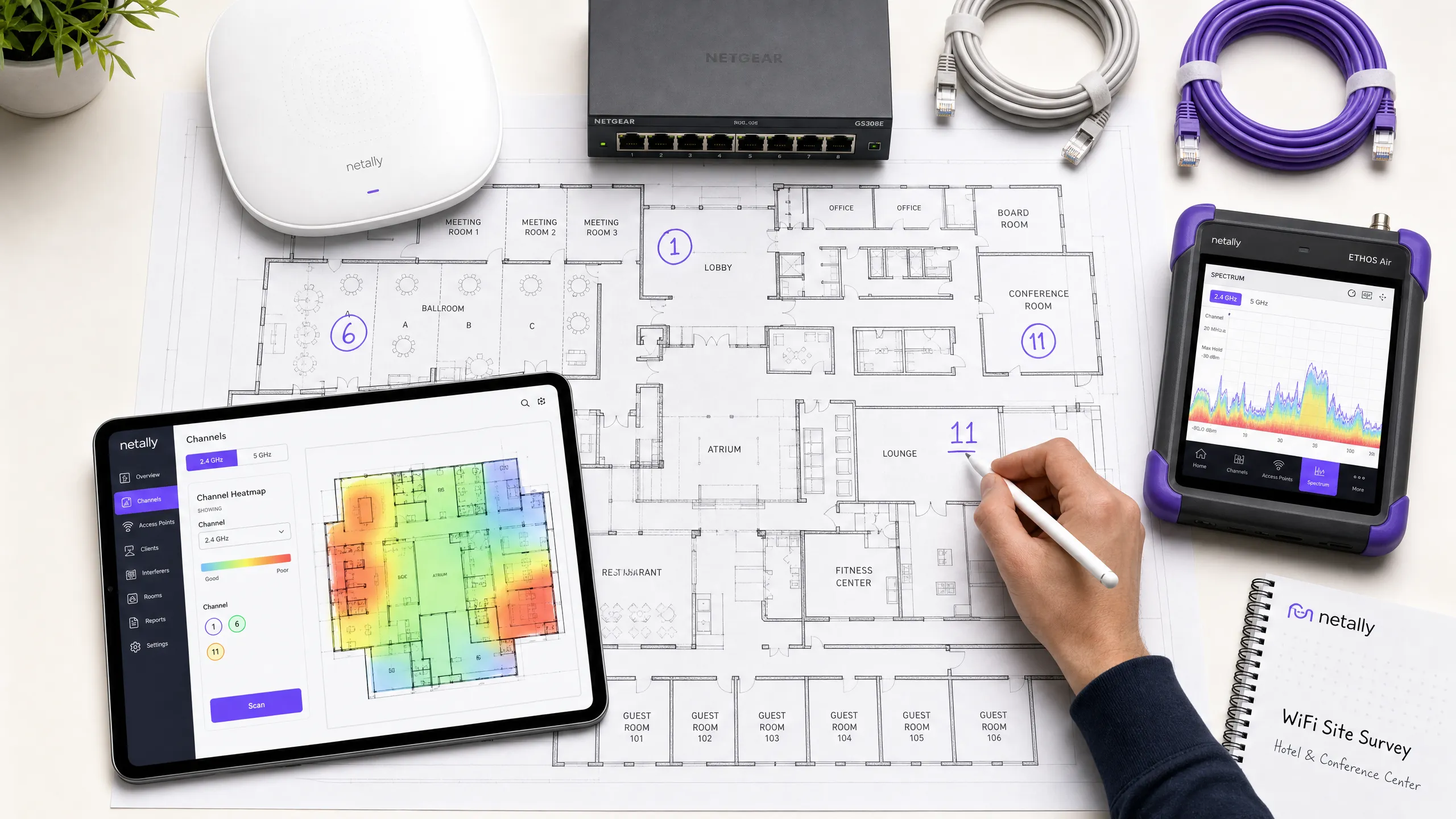
चरण 1: बेसलाइन RF ऑडिट
कोई भी कॉन्फ़िगरेशन परिवर्तन करने से पहले, आपको RF वातावरण की वर्तमान स्थिति को समझना होगा। इसके लिए व्यापक माप उपकरणों की आवश्यकता होती है, न कि केवल एक स्मार्टफोन ऐप की।
- पैसिव स्पेक्ट्रम विश्लेषण: नॉइज़ फ्लोर को मापने और गैर-WiFi हस्तक्षेप स्रोतों की पहचान करने के लिए एक समर्पित स्पेक्ट्रम विश्लेषक (जैसे, Ekahau Sidekick, NetAlly AirCheck) का उपयोग करें। एक साफ वातावरण आमतौर पर लगभग -95 dBm का नॉइज़ फ्लोर प्रदर्शित करता है।
- पड़ोसी नेटवर्क सर्वेक्षण: सभी दृश्यमान Basic Service Set Identifiers (BSSIDs), उनके ऑपरेटिंग चैनलों और Received Signal Strength Indicators (RSSI) को सूचीबद्ध करें। रिटेल पार्क या बहु-किराएदार कार्यालय भवनों जैसे वातावरणों में, बाहरी नेटवर्क बेकाबू हस्तक्षेप का एक प्राथमिक स्रोत होते हैं।
- क्लाइंट प्रदर्शन मेट्रिक्स: केवल RSSI के बजाय Signal-to-Noise Ratio (SNR) का विश्लेषण करें। 20 dB से नीचे का SNR क्लाइंट्स को कम Modulation and Coding Scheme (MCS) इंडेक्स का उपयोग करने के लिए मजबूर करेगा, जिससे थ्रूपुट कम हो जाएगा। विश्वसनीय प्रदर्शन के लिए 25 dB या उससे अधिक का SNR लक्षित करें।
चरण 2: चैनल प्लान डिज़ाइन
बेसलाइन डेटा से लैस होकर, एक निश्चित चैनल प्लान तैयार करें।
- 2.4 GHz रणनीति: चैनल 1, 6 और 11 के उपयोग को सख्ती से लागू करें। यदि घनत्व बहुत अधिक है, तो चुनिंदा एक्सेस पॉइंट्स पर 2.4 GHz रेडियो को अक्षम करें, जिससे पुराने IoT उपकरणों के लिए कवरेज बनाए रखते हुए को-चैनल हस्तक्षेप को कम करने के लिए एक "सॉल्ट एंड पेपर" डिज़ाइन तैयार हो सके।
- 5 GHz रणनीति: नॉन-ओवरलैपिंग चैनलों की अधिकतम संख्या का उपयोग करें, जिसमें DFS चैनल भी शामिल हैं यदि आपके क्षेत्र में रडार गतिविधि कम है।
- चैनल चौड़ाई का चयन: उच्च-घनत्व वाले क्षेत्रों (जैसे, सम्मेलन कक्ष, स्टेडियम) के लिए 20 MHz चैनलों को मानकीकृत करें। मध्यम-घनत्व वाले क्षेत्रों (जैसे, होटल के कमरे, ओपन-प्लान कार्यालय) में 40 MHz चैनलों का उपयोग करें। जब तक बहुत कम-घनत्व, उच्च-थ्रूपुट परिदृश्यों में डिप्लॉय न किया जा रहा हो, तब तक 80 MHz चैनलों से बचें।
- ट्रांसमिट पावर ट्यूनिंग: चैनल प्लानिंग और ट्रांसमिट पावर अटूट रूप से जुड़े हुए हैं। प्रत्येक एक्सेस पॉइंट के सेल आकार को सिकोड़ने के लिए ट्रांसमिट पावर को कम करें, जिससे एक ही चैनल पर APs के बीच ओवरलैप (और इस प्रकार हस्तक्षेप) कम से कम हो। को-चैनल APs के बीच 15-20 dBm के अलगाव का लक्ष्य रखें।
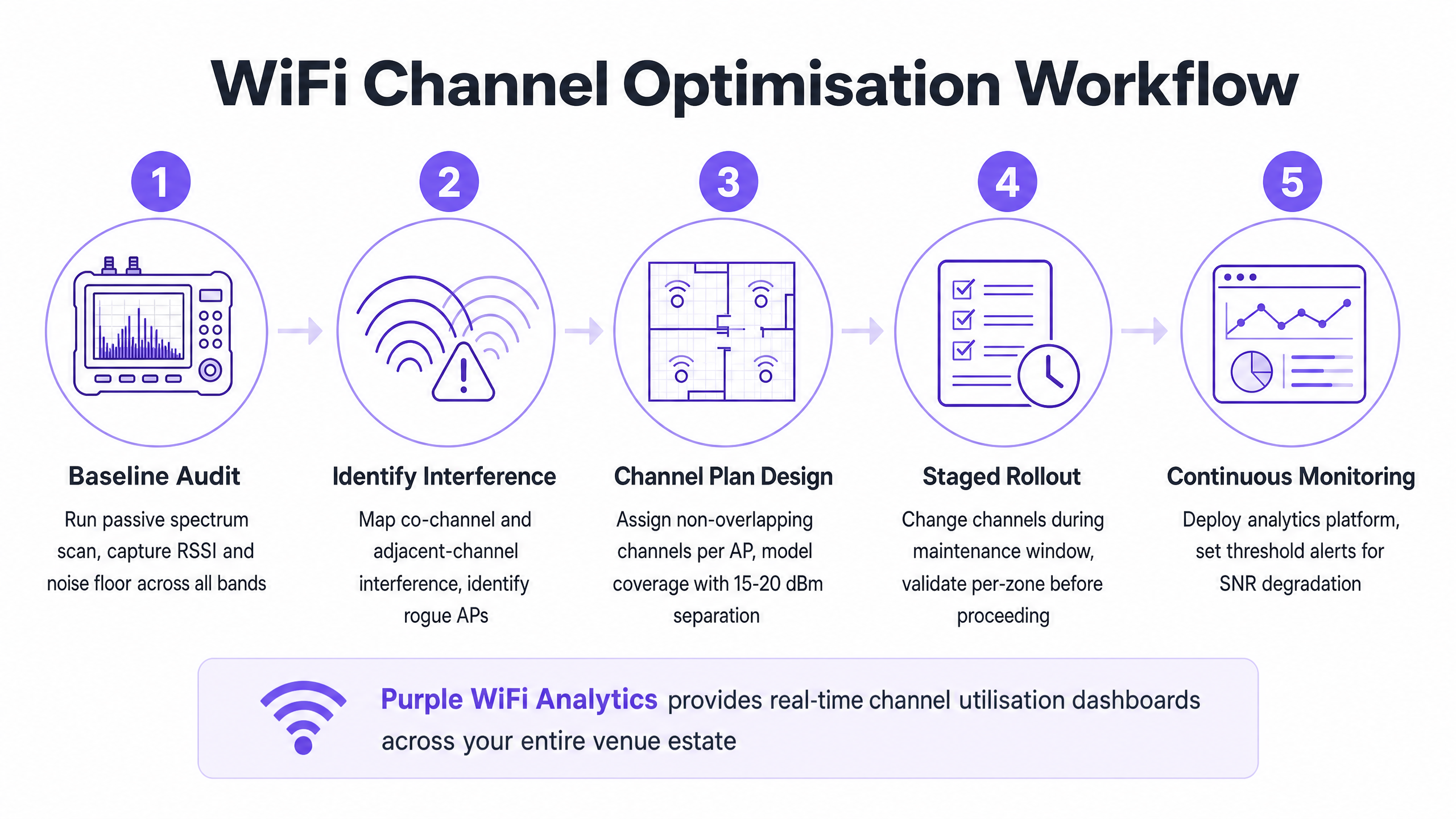
चरण 3: चरणबद्ध रोलआउट और सत्यापन
व्यावसायिक घंटों के दौरान या पूरे एस्टेट में एक साथ कभी भी वैश्विक चैनल परिवर्तन लागू न करें।
- रखरखाव विंडो (Maintenance Windows): रेडियो रीसेट से होने वाले व्यवधान को कम करने के लिए सबसे कम उपयोग की अवधि (आमतौर पर 02:00 - 05:00) के दौरान बदलावों को शेड्यूल करें।
- क्षेत्रीय डिप्लॉयमेंट (Zonal Deployment): तार्किक क्षेत्रों में नई योजना को रोल आउट करें (जैसे, एक समय में एक मंजिल या एक विंग)।
- परिवर्तन के बाद सत्यापन: नई योजना लागू करने के बाद, बेसलाइन ऑडिट में उपयोग किए गए समान उपकरणों का उपयोग करके परिवर्तनों को सत्यापित करें। सुनिश्चित करें कि को-चैनल हस्तक्षेप कम हो गया है और SNR लक्ष्यों को पूरा किया जा रहा है।
चैनल ऑप्टिमाइज़ेशन रणनीतियों पर हमारे 10 मिनट के तकनीकी ब्रीफिंग को सुनें:
सर्वोत्तम अभ्यास और जोखिम शमन
ऑटो-चैनल एल्गोरिदम के नुकसान
अधिकांश एंटरप्राइज़ WLAN कंट्रोलर में स्वचालित Radio Resource Management (RRM) या ऑटो-चैनल चयन की सुविधा होती है। हालांकि छोटे डिप्लॉयमेंट के लिए सुविधाजनक होने के बावजूद, ये एल्गोरिदम अक्सर उच्च-घनत्व वाले वातावरण में हानिकारक होते हैं। वे RF वातावरण के वैश्विक दृष्टिकोण के बजाय स्थानीय AP दृष्टिकोण के आधार पर निर्णय लेते हैं, जिससे अक्सर अनुपयुक्त चैनल असाइनमेंट होते हैं और परिचालन घंटों के दौरान विघटनकारी, क्रमिक चैनल परिवर्तन होते हैं।
सर्वोत्तम अभ्यास: जटिल स्थानों में, ऑटो-चैनल चयन को अक्षम करें। कठोर साइट सर्वेक्षणों के आधार पर मैन्युअल रूप से इंजीनियर, स्थिर (static) चैनल योजना लागू करें। कंट्रोलर की RRM सुविधाओं का उपयोग केवल महत्वपूर्ण RF परिवर्तनों पर अलर्ट करने के लिए करें, न कि स्वचालित सुधार के लिए।
को-चैनल हस्तक्षेप (CCI) को संबोधित करना
घने डिप्लॉयमेंट में CCI प्राथमिक प्रदर्शन नाशक है। शमन तकनीकों की गहरी समझ के लिए, Resolving Co-Channel Interference in Enterprise Deployments पर हमारी व्यापक मार्गदर्शिका देखें।
निरंतर निगरानी का महत्व
RF वातावरण के विकसित होने के साथ-साथ एक स्थिर चैनल योजना समय के साथ खराब हो जाएगी—नए पड़ोसी नेटवर्क दिखाई देते हैं, संरचनात्मक परिवर्तन होते हैं, या नए IoT डिवाइस डिप्लॉय किए जाते हैं। चैनल ऑप्टिमाइज़ेशन कोई "सेट एंड फॉरगेट" (सेट करके भूल जाने वाला) कार्य नहीं है।
सर्वोत्तम अभ्यास: एक एनालिटिक्स प्लेटफॉर्म का उपयोग करके निरंतर निगरानी लागू करें। Purple's WiFi Analytics क्लाइंट घनत्व, सत्र गुणवत्ता और स्थान-व्यापी थ्रूपुट प्रवृत्तियों में आवश्यक दृश्यता प्रदान करता है। SNR गिरावट या बढ़ी हुई पुनः प्रयास दरों के लिए थ्रेशोल्ड अलर्ट सेट करें ताकि सक्रिय रूप से पहचान की जा सके कि चैनल योजना में कब संशोधन की आवश्यकता है।
ROI और व्यावसायिक प्रभाव
अपने WiFi चैनल प्लान को ऑप्टिमाइज़ करने के लिए समय और उपकरणों में निवेश की आवश्यकता होती है, लेकिन निवेश पर रिटर्न (ROI) पर्याप्त और मापने योग्य है।
- बढ़ा हुआ कुल थ्रूपुट: को-चैनल हस्तक्षेप को कम करके और चैनल की चौड़ाई को ऑप्टिमाइज़ करके, स्थान अक्सर नए हार्डवेयर को डिप्लॉय किए बिना कुल नेटवर्क क्षमता में 20-40% की वृद्धि प्राप्त कर सकते हैं।
- कम सपोर्ट ओवरहेड: एक स्थिर RF वातावरण "धीमे WiFi" या रुक-रुक कर होने वाले डिस्कनेक्शन से संबंधित हेल्पडेस्क टिकटों को काफी कम कर देता है, जिससे परिचालन सहायता लागत कम हो जाती है।
- बेहतर उपयोगकर्ता अनुभव: Guest WiFi पर निर्भर वातावरणों के लिए, जैसे कि Hospitality या Retail , विश्वसनीय कनेक्टिविटी सीधे उच्च ग्राहक संतुष्टि स्कोर और कैप्टिव पोर्टल के साथ बढ़े हुए जुड़ाव से संबंधित है।
- परिचालन विश्वसनीयता: पॉइंट-ऑफ-सेल टर्मिनलों से लेकर हैंडहेल्ड इन्वेंट्री स्कैनर तक, महत्वपूर्ण व्यावसायिक प्रणालियाँ मजबूत वायरलेस कनेक्टिविटी पर निर्भर करती हैं। एक साफ चैनल योजना यह सुनिश्चित करती है कि ये प्रणालियाँ बिना किसी रुकावट के काम करें, जिससे राजस्व और परिचालन दक्षता की रक्षा होती है।
RF स्पेक्ट्रम को एक महत्वपूर्ण, प्रबंधनीय संसाधन मानकर, IT लीडर अपने वायरलेस बुनियादी ढांचे को निराशा के स्रोत से एंटरप्राइज़ संचालन के लिए एक विश्वसनीय आधार में बदल सकते हैं।
Definiciones clave
Interferencia de cocanal (CCI)
Interferencia que se produce cuando dos o más puntos de acceso funcionan en el mismo canal de frecuencia dentro del alcance del otro, lo que obliga a los dispositivos a compartir el tiempo de transmisión y a esperar a que el medio quede libre.
La CCI es la causa principal de la degradación del rendimiento en despliegues densos donde la reutilización de canales está mal planificada.
Interferencia de canal adyacente (ACI)
Interferencia causada por frecuencias superpuestas (por ejemplo, el uso de los canales 1 y 3 en la banda de 2,4 GHz), que corrompe las transmisiones en lugar de compartir el tiempo de transmisión.
La ACI es altamente destructiva y debe evitarse adhiriéndose estrictamente a asignaciones de canales no superpuestos.
Selección dinámica de frecuencia (DFS)
Un requisito regulatorio en la banda de 5 GHz por el cual los puntos de acceso deben monitorizar las señales de radar y abandonar el canal si se detectan.
Aunque los canales DFS (UNII-2) añaden complejidad operativa, son esenciales para lograr una reutilización de canales adecuada en entornos de alta densidad.
Relación señal-ruido (SNR)
La diferencia en decibelios (dB) entre la intensidad de la señal recibida y el umbral de ruido de fondo.
La SNR es un predictor más preciso del rendimiento del cliente que el RSSI por sí solo. Una SNR más alta permite tasas de modulación más rápidas.
Esquema de modulación y codificación (MCS)
Un valor de índice que representa la combinación del tipo de modulación y la tasa de codificación utilizada para una transmisión, determinando la velocidad de datos.
Un entorno de RF limpio con una SNR alta permite a los clientes negociar índices MCS más altos, lo que se traduce en un rendimiento más rápido.
Acceso múltiple por detección de portadora y evitación de colisiones (CSMA/CA)
El protocolo utilizado por las redes 802.11 en el que los dispositivos escuchan el medio inalámbrico antes de transmitir para evitar colisiones.
CSMA/CA gestiona el tiempo de transmisión en canales compartidos, pero genera una sobrecarga significativa y reduce el rendimiento en entornos con alta CCI.
Ruido de fondo (Noise Floor)
La medida de la energía de RF de fondo en el entorno, expresada normalmente en dBm.
Un ruido de fondo alto reduce la SNR efectiva, degradando el rendimiento. Identificar y mitigar las fuentes de ruido de RF es un paso crítico en la optimización de canales.
Indicador de fuerza de la señal recibida (RSSI)
Una medida de la potencia presente en una señal de radio recibida.
Aunque es útil para el mapeo básico de cobertura, el RSSI debe evaluarse junto con el ruido de fondo (para determinar la SNR) para un análisis de rendimiento preciso.
Ejemplos prácticos
Un hotel de 300 habitaciones en un entorno urbano denso experimenta un rendimiento deficiente de WiFi durante las horas punta de la tarde. El despliegue actual utiliza canales de 80 MHz en la banda de 5 GHz y la selección automática de canales está activada. Los huéspedes informan de desconexiones frecuentes y velocidades de streaming lentas.
- Realizar un análisis de espectro de línea base durante las horas punta para cuantificar la interferencia.
- Desactivar la selección automática de canales en el controlador WLAN para evitar reinicios de radio disruptivos.
- Reconfigurar las radios de 5 GHz de anchos de canal de 80 MHz a 20 MHz. Esto aumenta el número de canales no superpuestos disponibles de 6 a más de 24.
- Implementar un plan de canales estático, garantizando que los puntos de acceso adyacentes funcionen en canales diferentes y que los puntos de acceso cocanal estén separados por al menos 15-20 dBm de atenuación de señal.
- Validar la nueva configuración midiendo la SNR y las tasas de reintento en las áreas previamente problemáticas.
Un gran almacén minorista depende de escáneres portátiles de 2,4 GHz para la gestión de inventario. Los escáneres pierden con frecuencia su conexión a la red, lo que obliga al personal a reiniciar los dispositivos. Los puntos de acceso están configurados actualmente para utilizar los canales 1, 4, 8 y 11.
- Realizar un escaneo de RF pasivo para identificar fuentes de interferencia que no sean de Wi-Fi en la banda de 2,4 GHz (por ejemplo, balizas Bluetooth, cámaras de seguridad heredadas).
- Reconfigurar todas las radios de 2,4 GHz para utilizar únicamente los canales no superpuestos: 1, 6 y 11.
- Ajustar la potencia de transmisión para minimizar la superposición de celdas, garantizando que los escáneres realicen una transición fluida (roaming) entre los puntos de acceso sin aferrarse a señales lejanas y débiles (clientes persistentes o 'sticky').
- Implementar una monitorización para realizar el seguimiento del comportamiento de roaming y las tasas de reintento de los escáneres portátiles.
Preguntas de práctica
Q1. Estás diseñando el despliegue de WiFi para un centro de conferencias de alta densidad. El recinto requiere la máxima capacidad agregada para soportar miles de dispositivos de clientes concurrentes. ¿Qué estrategia de ancho de canal deberías adoptar para la banda de 5 GHz?
Sugerencia: Considera el equilibrio entre el rendimiento individual máximo y el número de canales no superpuestos disponibles para su reutilización.
Ver respuesta modelo
Estandarizar en canales de 20 MHz. Aunque los canales de 80 MHz proporcionan un mayor rendimiento máximo para un solo usuario, reducen drásticamente el número de canales no superpuestos disponibles. En un entorno de alta densidad, el uso de canales de 20 MHz maximiza la reutilización de canales, reduce la interferencia de cocanal y proporciona la mayor capacidad agregada para el recinto.
Q2. Durante un estudio de cobertura (site survey) de un parque comercial, descubres que varios negocios vecinos tienen sus puntos de acceso funcionando en el canal 4 en la banda de 2,4 GHz. ¿Cómo deberías configurar tus puntos de acceso en respuesta?
Sugerencia: Evalúa el impacto de la interferencia de canal adyacente frente a la interferencia de cocanal.
Ver respuesta modelo
Debes configurar tus puntos de acceso para utilizar los canales 1, 6 o 11, seleccionando específicamente el canal (probablemente el 11) que esté más alejado del canal 4 que causa la interferencia. Funcionar en el canal 4 causaría una grave interferencia de canal adyacente. Incluso funcionar en el canal 6 podría sufrir cierta superposición de señales fuertes en el canal 4. Es mejor aceptar cierta interferencia de cocanal en un canal estándar (1, 6, 11) que introducir interferencia de canal adyacente.
Q3. Tras desplegar un nuevo plan de canales estático en un hospital, observas que los clientes de una sala específica experimentan velocidades lentas, a pesar de informar de un RSSI fuerte (-65 dBm). ¿Cuál es la causa más probable y cómo la investigas?
Sugerencia: El RSSI solo mide la intensidad de la señal, no la calidad de la misma. ¿Qué métrica determina la señal real utilizable?
Ver respuesta modelo
La causa más probable es un ruido de fondo alto que genera una baja relación señal-ruido (SNR). Incluso con un RSSI fuerte, si el ruido de fondo es alto (por ejemplo, -75 dBm), la SNR resultante (10 dB) es demasiado baja para una modulación de alta velocidad. Deberías utilizar un analizador de espectro para identificar la fuente del ruido de RF en esa sala específica y mitigarlo.
Continúe leyendo esta serie
Comprensión de RSSI y la intensidad de la señal para una planificación de canales óptima
Esta guía ofrece un análisis técnico profundo y exhaustivo sobre RSSI, la relación señal-ruido (SNR) y los principios de propagación de RF para una planificación de canales óptima. Proporciona a los responsables de TI, arquitectos de redes y directores de operaciones de recintos estrategias prácticas para mitigar la interferencia de canal adyacente y cocanal, optimizar la ubicación de los puntos de acceso y aprovechar la analítica para lograr un impacto empresarial medible en entornos de hostelería, comercio minorista y sector público.
20MHz vs 40MHz vs 80MHz: ¿Qué ancho de canal debería utilizar?
Esta guía proporciona una referencia técnica definitiva e independiente del proveedor para directores de TI, arquitectos de red y directores de operaciones de espacios sobre cómo seleccionar el ancho de canal WiFi correcto (20MHz, 40MHz u 80MHz) en despliegues empresariales en los sectores de hostelería, retail, eventos y sector público. Cubre los mecanismos subyacentes de IEEE 802.11, las compensaciones de capacidad en el mundo real y una guía de despliegue paso a paso para ayudar a los equipos a tomar la decisión correcta este trimestre. Comprender la selección del ancho de canal es una de las decisiones de mayor impacto en cualquier diseño de LAN inalámbrica, ya que afecta directamente al rendimiento, las interferencias, la capacidad de densidad de clientes y la fiabilidad de los servicios orientados a los huéspedes.
Wi-Fi 6 vs Wi-Fi 5: ¿Resuelve la interferencia de canales?
Esta guía ofrece un análisis técnico profundo sobre cómo Wi-Fi 6 (802.11ax) aborda la interferencia de canales en entornos empresariales de alta densidad mediante OFDMA y BSS Coloring. Proporciona a los directores de TI, arquitectos de red y CTO estrategias de despliegue prácticas, casos de estudio reales de los sectores de hostelería y salud, y un marco para evaluar el ROI de las actualizaciones de infraestructura en recintos donde el rendimiento inalámbrico es crítico para el negocio.