How to Analyse and Change Your WiFi Channel for Maximum Speed
This authoritative technical reference guide equips IT managers and network architects with the methodologies to analyse RF environments and implement optimal WiFi channel plans. It provides actionable frameworks to mitigate co-channel interference, maximise throughput, and ensure robust connectivity across high-density enterprise deployments.
Listen to this guide
View podcast transcript
Executive Summary
In high-density enterprise environments—whether a 500-room hotel, a multi-storey retail estate, or a public-sector campus—wireless performance is no longer just an additional amenity; it is critical operational infrastructure. Yet, many deployments suffer from low throughput, high retry rates, and intermittent connectivity issues, all stemming from a single rectifiable root cause: sub-optimal channel planning. Relying on default vendor configurations or simple auto-channel algorithms in complex RF environments inevitably leads to co-channel interference and spectrum congestion.
This technical reference guide provides a vendor-neutral, engineering-based methodology to analyse your current RF environment and implement a definitive channel plan. We will examine the operational physics of the 2.4 GHz, 5 GHz, and 6 GHz bands, outline a structured approach to spectrum analysis, and provide practical frameworks for mitigating interference. By treating channel optimisation as an ongoing operational discipline rather than a one-time deployment task, network teams can achieve measurable improvements in throughput, reduce support ticket volumes, and ensure reliable connectivity for both guest devices and critical operational infrastructure.
Technical Deep Dive: Understanding the RF Spectrum
To make informed decisions about channel allocation, network architects must understand the underlying mechanics of 802.11 standards and how different frequency bands behave in the physical environment.
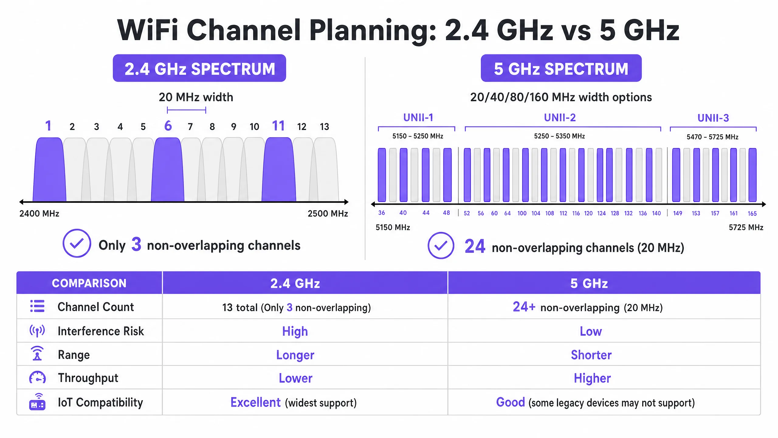
The 2.4 GHz Band: Managing Scarcity
The 2.4 GHz band is the busiest slice of unlicensed spectrum. Whilst it offers superior propagation characteristics—allowing signals to penetrate walls and floors more effectively than higher frequencies—its channel structure is fundamentally limited. In most regulatory domains (including Europe and North America), this band offers channels that are 20 MHz wide but spaced only 5 MHz apart.
This mathematics dictates that only three non-overlapping channels are available: 1, 6, and 11. Any deployment utilizing channels outside this trio (e.g., channels 2, 3, or 4) introduces adjacent-channel interference. Unlike co-channel interference, where devices can coordinate airtime using CSMA/CA, adjacent-channel interference corrupts transmissions, resulting in high retry rates and severe throughput degradation.
Furthermore, the 2.4 GHz band is shared with numerous non-WiFi interferers, including Bluetooth devices, microwave ovens, and legacy IoT sensors. When optimising this band, the primary objective is interference mitigation rather than maximum throughput.
The 5 GHz Band: Capacity and Complexity
The 5 GHz band offers significantly higher capacity, providing 24 or more non-overlapping 20 MHz channels depending on the regulatory domain. This spectrum is divided into Unlicensed National Information Infrastructure (UNII) sub-bands:
- UNII-1 (Channels 36-48): These channels do not require Dynamic Frequency Selection (DFS) and are the safest starting point for high-density deployments.
- UNII-2 (Channels 52-144): These channels require DFS, meaning access points must monitor for radar signatures (such as weather or military radar) and vacate the channel if detected. Although DFS adds operational complexity, using UNII-2 is essential to achieve the necessary channel reuse in dense environments.
- UNII-3 (Channels 149-165): These channels are typically non-DFS but are subject to varying power restrictions depending on the region.
In the 5 GHz band, network architects must balance channel width and channel availability. Although 80 MHz channels (the default for 802.11ac and Wi-Fi 6) offer higher peak throughput for individual clients, they consume four 20 MHz channels, significantly reducing the number of non-overlapping channels available for reuse. In high-density venues, wider channels often cause co-channel interference, reducing overall capacity.
The 6 GHz Frontier (Wi-Fi 6E and Wi-Fi 7)
The introduction of the 6 GHz band represents the most significant expansion of WiFi spectrum in two decades, adding up to 1200 MHz of greenfield spectrum. It provides 59 additional 20 MHz channels, entirely free from legacy device interference and DFS requirements. For venues upgrading hardware, 6 GHz allows for the practical deployment of 80 MHz or 160 MHz channels in high-density areas. However, its shorter wavelength means shorter range and penetration, requiring more dense access point placement.
Implementation Guide: Channel Optimisation Workflow
Optimising your WiFi channel plan requires a systematic approach that goes from baseline measurement to engineered design and validated deployment.
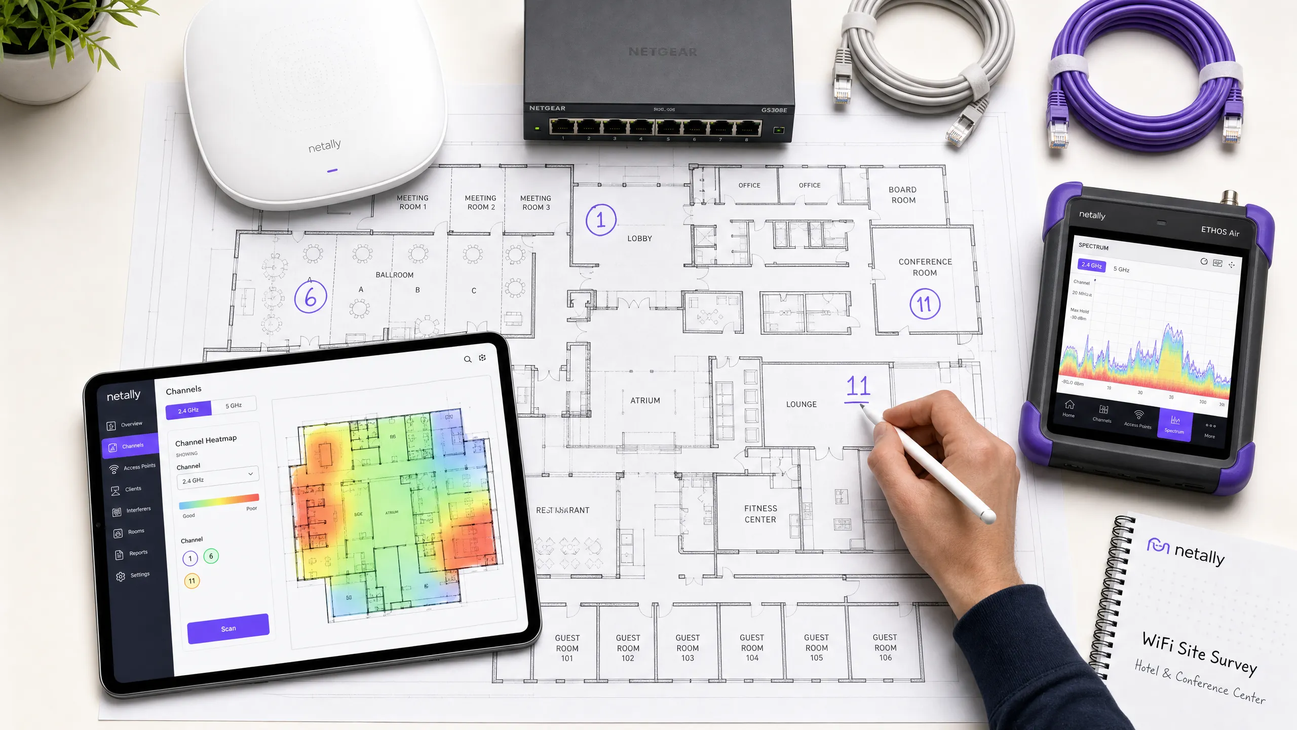
Step 1: Baseline RF Audit
Before making any configuration changes, you must understand the current state of the RF environment. This requires comprehensive measurement tools, not just a smartphone app.
- Passive Spectrum Analysis: Use a dedicated spectrum analyser (e.g., Ekahau Sidekick, NetAlly AirCheck) to measure the noise floor and identify non-WiFi interference sources. A clean environment typically displays a noise floor of around -95 dBm.
- Neighbouring Network Survey: List all visible Basic Service Set Identifiers (BSSIDs), their operating channels, and Received Signal Strength Indicators (RSSI). In environments like retail parks or multi-tenant office buildings, external networks are a primary source of uncontrollable interference.
- Client Performance Metrics: Analyse Signal-to-Noise Ratio (SNR) instead of just RSSI. An SNR below 20 dB will force clients to use a lower Modulation and Coding Scheme (MCS) index, reducing throughput. Target an SNR of 25 dB or higher for reliable performance.
Step 2: Channel Plan Design
Equipped with baseline data, design a definitive channel plan.
- 2.4 GHz Strategy: Strictly enforce the use of channels 1, 6, and 11. If density is extremely high, selectively disable 2.4 GHz radios on certain access points to create a "salt-and-pepper" design, reducing co-channel interference while maintaining coverage for legacy IoT devices.
- 5 GHz Strategy: Use the maximum number of non-overlapping channels, including DFS channels if radar activity is low in your area.
- Channel Width Selection: Standardise on 20 MHz channels for high-density areas (e.g., conference rooms, stadiums). Use 40 MHz channels in medium-density areas (e.g., hotel rooms, open-plan offices). Avoid 80 MHz channels unless deploying in very low-density, high-throughput scenarios.
- Transmit Power Tuning: Channel planning and transmit power are inextricably linked. Reduce transmit power to shrink each access point's cell size, thereby minimising overlap (and thus interference) between APs on the same channel. Aim for 15-20 dBm of separation between co-channel APs.
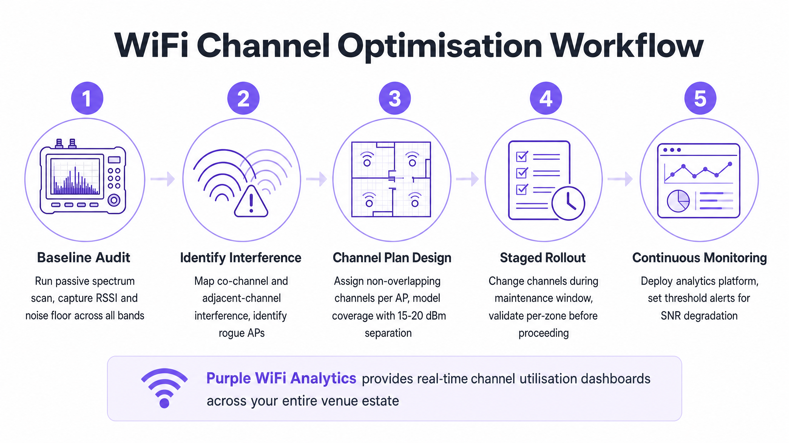
Step 3: Phased Rollout and Validation
Never apply global channel changes simultaneously across the entire estate or during business hours.
- Maintenance Windows: Schedule changes during the lowest-utilisation periods (typically 02:00 - 05:00) to minimise disruption from radio resets.
- Zonal Deployment: Roll out the new plan in logical zones (e.g., one floor or one wing at a time).
- Post-Change Validation: After applying the new plan, validate the changes using the same tools used in the baseline audit. Ensure co-channel interference has decreased and SNR targets are being met.
Listen to our 10-minute technical briefing on channel optimisation strategies:
Best Practices and Risk Mitigation
The Pitfalls of Auto-Channel Algorithms
Most enterprise WLAN controllers feature automatic Radio Resource Management (RRM) or auto-channel selection. Whilst convenient for smaller deployments, these algorithms are often detrimental in high-density environments. They make decisions based on a local AP perspective rather than a global view of the RF environment, frequently leading to sub-optimal channel assignments and disruptive, cascading channel changes during operational hours.
Best Practice: In complex venues, disable auto-channel selection. Implement a manually engineered, static channel plan based on rigorous site surveys. Use the controller's RRM features only to alert on significant RF changes, not for automated correction.
Addressing Co-Channel Interference (CCI)
CCI is the primary performance killer in dense deployments. For a deeper understanding of mitigation techniques, see our comprehensive guide on Resolving Co-Channel Interference in Enterprise Deployments .
The Importance of Continuous Monitoring
A static channel plan will degrade over time as the RF environment evolves—new neighbouring networks appear, structural changes occur, or new IoT devices are deployed. Channel optimisation is not a "set and forget" task.
Best Practice: Implement continuous monitoring utilising an analytics platform. Purple's WiFi Analytics provides essential visibility into client density, session quality, and venue-wide throughput trends. Set threshold alerts for SNR degradation or increased retry rates to proactively identify when the channel plan requires revision.
ROI and Business Impact
Investing time and tools into optimising your WiFi channel plan requires effort, but the return on investment (ROI) is substantial and measurable.
- Increased Aggregate Throughput: By minimising co-channel interference and optimising channel width, venues can often achieve a 20-40% increase in aggregate network capacity without deploying new hardware.
- Reduced Support Overhead: A stable RF environment significantly reduces helpdesk tickets related to "slow WiFi" or intermittent disconnections, lowering operational support costs.
- Enhanced User Experience: For environments relying on Guest WiFi , such as Hospitality or Retail , reliable connectivity directly correlates with higher customer satisfaction scores and increased engagement with the Captive Portal.
- Operational Reliability: From point-of-sale terminals to handheld inventory scanners, critical business systems rely on robust wireless connectivity. A clean channel plan ensures these systems operate without disruption, protecting revenue and operational efficiency. By treating the RF spectrum as a critical, manageable resource, IT leaders can transform their wireless infrastructure from a source of frustration into a reliable foundation for enterprise operations.
Key Definitions
Co-Channel Interference (CCI)
Interference that occurs when two or more access points operate on the same frequency channel within range of each other, forcing devices to share airtime and wait for the medium to clear.
CCI is the primary cause of degraded throughput in dense deployments where channel reuse is poorly planned.
Adjacent-Channel Interference (ACI)
Interference caused by overlapping frequencies (e.g., using channels 1 and 3 in the 2.4 GHz band), which corrupts transmissions rather than sharing airtime.
ACI is highly destructive and must be avoided by strictly adhering to non-overlapping channel assignments.
Dynamic Frequency Selection (DFS)
A regulatory requirement in the 5 GHz band where access points must monitor for radar signals and vacate the channel if detected.
While DFS channels (UNII-2) add operational complexity, they are essential for achieving adequate channel reuse in high-density environments.
Signal-to-Noise Ratio (SNR)
The difference in decibels (dB) between the received signal strength and the background noise floor.
SNR is a more accurate predictor of client performance than RSSI alone. A higher SNR allows for faster modulation rates.
Modulation and Coding Scheme (MCS)
An index value that represents the combination of modulation type and coding rate used for a transmission, determining the data rate.
A clean RF environment with high SNR allows clients to negotiate higher MCS indices, resulting in faster throughput.
Carrier Sense Multiple Access with Collision Avoidance (CSMA/CA)
The protocol used by 802.11 networks where devices listen to the wireless medium before transmitting to avoid collisions.
CSMA/CA manages airtime on shared channels but leads to significant overhead and reduced throughput in environments with high CCI.
Noise Floor
The measure of the background RF energy in the environment, typically expressed in dBm.
A high noise floor reduces the effective SNR, degrading performance. Identifying and mitigating sources of RF noise is a critical step in channel optimisation.
Received Signal Strength Indicator (RSSI)
A measurement of the power present in a received radio signal.
While useful for basic coverage mapping, RSSI must be evaluated alongside the noise floor (to determine SNR) for accurate performance analysis.
Worked Examples
A 300-room hotel in a dense urban environment is experiencing poor WiFi performance during peak evening hours. The current deployment uses 80 MHz channels on the 5 GHz band, and auto-channel selection is enabled. Guests report frequent disconnections and slow streaming speeds.
- Conduct a baseline spectrum analysis during peak hours to quantify the interference.
- Disable auto-channel selection on the WLAN controller to prevent disruptive radio resets.
- Reconfigure the 5 GHz radios from 80 MHz to 20 MHz channel widths. This increases the number of available non-overlapping channels from 6 to 24+.
- Implement a static channel plan, ensuring adjacent access points operate on different channels and co-channel access points are separated by at least 15-20 dBm of signal attenuation.
- Validate the new configuration by measuring SNR and retry rates in previously problematic areas.
A large retail warehouse relies on 2.4 GHz handheld scanners for inventory management. The scanners frequently drop their connection to the network, requiring staff to reboot the devices. The access points are currently configured to use channels 1, 4, 8, and 11.
- Perform a passive RF scan to identify sources of non-Wi-Fi interference in the 2.4 GHz band (e.g., Bluetooth beacons, legacy security cameras).
- Reconfigure all 2.4 GHz radios to use only the non-overlapping channels: 1, 6, and 11.
- Adjust transmit power to minimise cell overlap, ensuring scanners roam seamlessly between access points without clinging to distant, weak signals (sticky clients).
- Implement monitoring to track the roaming behaviour and retry rates of the handheld scanners.
Practice Questions
Q1. You are designing the WiFi deployment for a high-density conference centre. The venue requires maximum aggregate capacity to support thousands of concurrent client devices. Which channel width strategy should you adopt for the 5 GHz band?
Hint: Consider the trade-off between peak individual throughput and the number of available non-overlapping channels for reuse.
View model answer
Standardise on 20 MHz channels. While 80 MHz channels provide higher peak throughput for a single user, they drastically reduce the number of available non-overlapping channels. In a high-density environment, using 20 MHz channels maximises channel reuse, reduces co-channel interference, and provides the highest aggregate capacity for the venue.
Q2. During a site survey of a retail park, you discover that several neighbouring businesses are operating their access points on channel 4 in the 2.4 GHz band. How should you configure your access points in response?
Hint: Evaluate the impact of adjacent-channel interference versus co-channel interference.
View model answer
You must configure your access points to use channels 1, 6, or 11, specifically selecting the channel (likely 11) that is furthest from the interfering channel 4. Operating on channel 4 would cause severe adjacent-channel interference. Even operating on channel 6 might suffer some overlap from strong signals on channel 4. It is better to accept some co-channel interference on a standard channel (1, 6, 11) than to introduce adjacent-channel interference.
Q3. After deploying a new static channel plan in a hospital, you notice that clients in a specific ward are experiencing slow speeds, despite reporting a strong RSSI (-65 dBm). What is the most likely cause, and how do you investigate?
Hint: RSSI only measures signal strength, not signal quality. What metric determines the actual usable signal?
View model answer
The most likely cause is a high noise floor leading to a low Signal-to-Noise Ratio (SNR). Even with a strong RSSI, if the noise floor is high (e.g., -75 dBm), the resulting SNR (10 dB) is too low for high-speed modulation. You should use a spectrum analyser to identify the source of the RF noise in that specific ward and mitigate it.
Continue reading in this series
Understanding RSSI and Signal Strength for Optimal Channel Planning
This guide provides a comprehensive technical deep-dive into RSSI, Signal-to-Noise Ratio (SNR), and RF propagation principles for optimal channel planning. It equips IT managers, network architects, and venue operations directors with actionable strategies to mitigate Co-Channel and Adjacent Channel Interference, optimise AP placement, and leverage analytics for measurable business impact across hospitality, retail, and public-sector environments.
20MHz vs 40MHz vs 80MHz: Which Channel Width Should You Use?
This guide provides a definitive, vendor-neutral technical reference for IT managers, network architects, and venue operations directors on selecting the correct WiFi channel width — 20MHz, 40MHz, or 80MHz — across enterprise deployments in hospitality, retail, events, and public-sector environments. It covers the underlying IEEE 802.11 mechanics, real-world capacity trade-offs, and step-by-step deployment guidance to help teams make the right call this quarter. Understanding channel width selection is one of the highest-leverage decisions in any wireless LAN design, directly impacting throughput, interference, client density support, and the reliability of guest-facing services.