Comment changer les canaux WiFi pour prévenir les interférences
Ce guide technique complet fournit aux responsables informatiques, aux architectes réseau et aux directeurs d'exploitation de sites une approche définitive et étape par étape pour identifier les sources d'interférences WiFi et modifier stratégiquement les canaux WiFi afin de les éliminer. Il couvre la planification des bandes 2,4 GHz et 5 GHz, l'analyse du spectre, la gestion des ressources radio (Radio Resource Management) et les considérations DFS, basées sur les normes IEEE 802.11 et des scénarios de déploiement réels. La mise en œuvre de ces stratégies apporte des améliorations mesurables en termes de débit réseau, de stabilité client et de retour sur investissement de l'infrastructure sans nécessiter de dépenses d'investissement en nouveau matériel.
Écouter ce guide
Voir la transcription du podcast
Résumé Exécutif
Pour les environnements d'entreprise — des vastes sites d' Hospitality aux espaces de Retail denses — un WiFi fiable n'est plus un avantage ; c'est une infrastructure critique. Les interférences restent le principal coupable des connexions interrompues, de la latence élevée et du faible débit, impactant directement l'efficacité opérationnelle et l'expérience Guest WiFi . Ce guide fournit aux architectes réseau et aux responsables informatiques une approche définitive et étape par étape pour identifier les sources d'interférences et modifier stratégiquement les canaux WiFi afin de les atténuer.
En mettant en œuvre les meilleures pratiques neutres vis-à-vis des fournisseurs pour la gestion du spectre, les organisations peuvent maximiser le retour sur investissement de leur infrastructure, assurer une itinérance client transparente et prendre en charge la densité croissante des appareils IoT et utilisateurs sans compromettre les normes de sécurité ou de conformité, y compris PCI DSS et GDPR. Le principe fondamental est simple : l'interférence est un problème de gestion du spectre, pas un problème matériel. Une configuration correcte de l'infrastructure existante résoudra, dans la plupart des cas, les problèmes de performance que les organisations attribuent à tort à une densité d'AP insuffisante ou à un équipement obsolète.
Approfondissement Technique
Comprendre la couche physique des réseaux IEEE 802.11 est essentiel avant d'apporter toute modification de configuration. Le spectre des radiofréquences (RF) est un support partagé régi par le protocole CSMA/CA (Carrier Sense Multiple Access with Collision Avoidance), et les interférences se répartissent généralement en deux catégories distinctes : les interférences co-canal (CCI) et les interférences de canal adjacent (ACI).
Les interférences co-canal (CCI) se produisent lorsque plusieurs points d'accès ou clients transmettent sur exactement le même canal. Bien que les protocoles 802.11 utilisent le CSMA/CA pour gérer cela — les appareils écoutent avant de transmettre — un CCI excessif force les appareils à attendre un temps d'antenne libre, réduisant drastiquement le débit et augmentant la latence. Il s'agit fondamentalement d'un problème de congestion plutôt que d'un véritable bruit RF, et le mécanisme CSMA/CA peut le gérer avec une certaine élégance.
Les interférences de canal adjacent (ACI) sont bien plus destructrices. Elles se produisent lorsque des AP fonctionnent sur des fréquences qui se chevauchent — par exemple, les canaux 2 et 4 dans la bande 2,4 GHz. Parce que les transmissions se chevauchent mais ne peuvent pas être décodées par le CSMA/CA, elles sont traitées comme du pur bruit, augmentant le plancher de bruit et provoquant des pertes de paquets et des retransmissions. Dans un lieu très fréquenté, l'ACI peut réduire le débit effectif de 60 à 70 % et est l'erreur de mauvaise configuration la plus courante rencontrée dans les déploiements d'entreprise.
Le dilemme de la bande 2,4 GHz
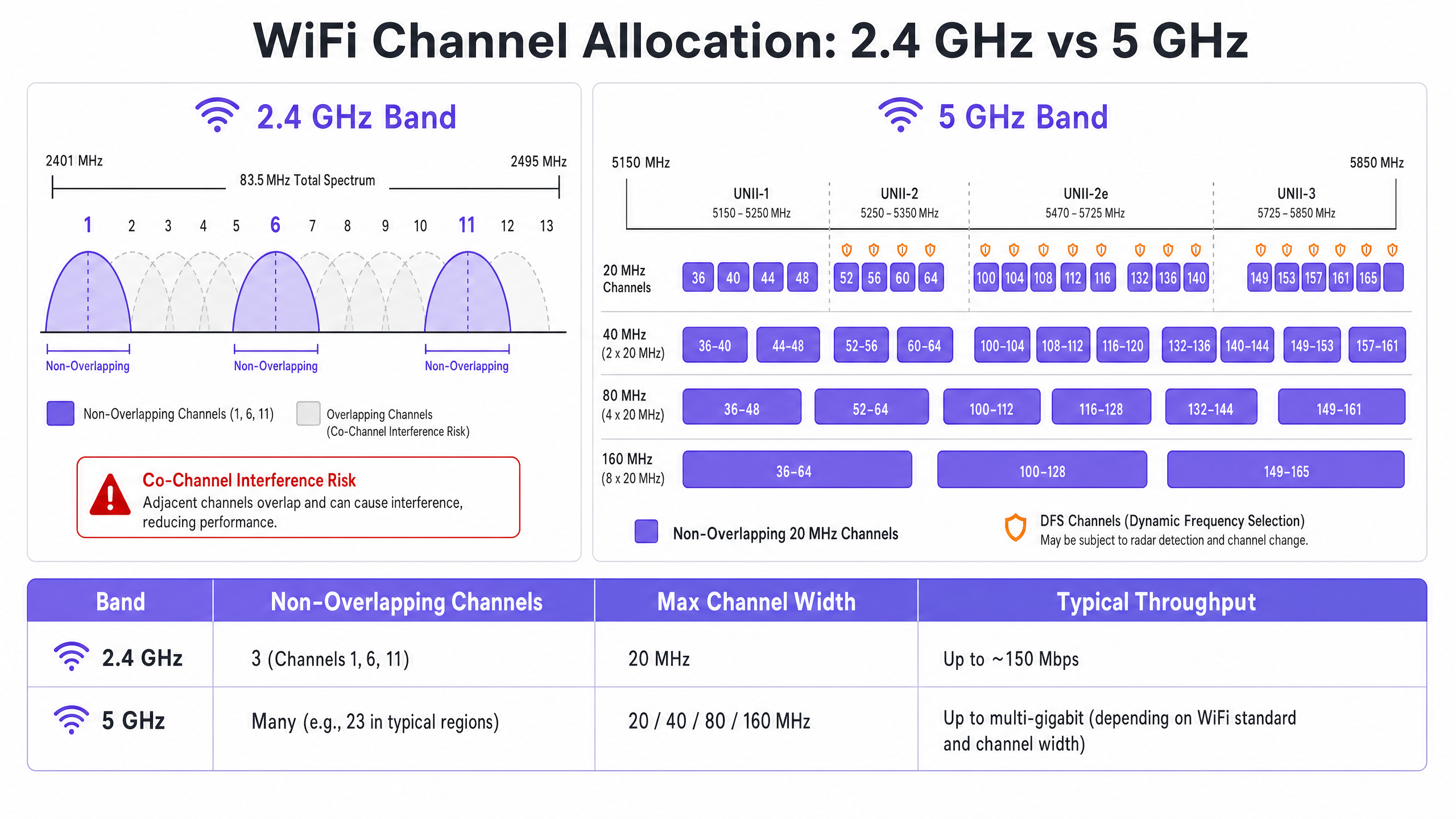
La bande 2,4 GHz offre une meilleure portée et pénétration des murs, mais est sévèrement limitée par un spectre restreint — environ 83,5 MHz au total. Bien qu'il existe 11 à 14 canaux selon le domaine réglementaire, seuls trois ne se chevauchent pas réellement : les canaux 1, 6 et 11. L'utilisation de tout autre canal dans un déploiement multi-AP garantit l'ACI. De plus, cette bande est encombrée d'interféreurs non-WiFi, y compris les appareils Bluetooth, les fours à micro-ondes et les téléphones sans fil DECT fonctionnant dans le même spectre. Pour une analyse détaillée de la coexistence de Bluetooth Low Energy avec l'infrastructure WiFi, consultez notre guide sur BLE Low Energy Explained for Enterprise . Pour un traitement plus large de la sélection des bandes de fréquences, reportez-vous à Wi Fi Frequencies: A Guide to Wi-Fi Frequencies in 2026 .
L'avantage de la bande 5 GHz
La bande 5 GHz offre un spectre nettement plus large, fournissant de nombreux canaux de 20 MHz non chevauchants à travers les sous-bandes UNII-1, UNII-2, UNII-2e et UNII-3. Cette bande est le choix par défaut correct pour le trafic client d'entreprise. Cependant, elle introduit deux complexités clés : les compromis du channel bonding et la sélection dynamique de fréquences (DFS).
Le channel bonding — combinant des canaux de 20 MHz en largeurs de 40, 80 ou 160 MHz — augmente le débit maximal pour un seul client mais réduit le nombre total de canaux indépendants disponibles. Dans les environnements à haute densité, cela provoque un CCI sévère. Les canaux DFS (principalement UNII-2 et UNII-2e) exigent des AP qu'ils surveillent les signaux radar et libèrent immédiatement le canal s'ils sont détectés, entraînant des déconnexions client. C'est une considération critique pour les sites proches des aéroports, des stations météorologiques ou des installations militaires.
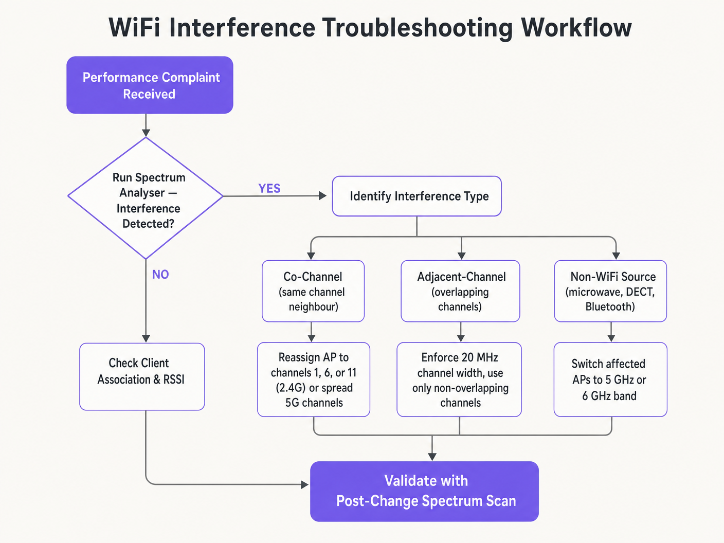
Guide d'implémentation
Changer les canaux WiFi ne devrait jamais être basé sur des suppositions. Cela nécessite une approche systématique et basée sur les données.
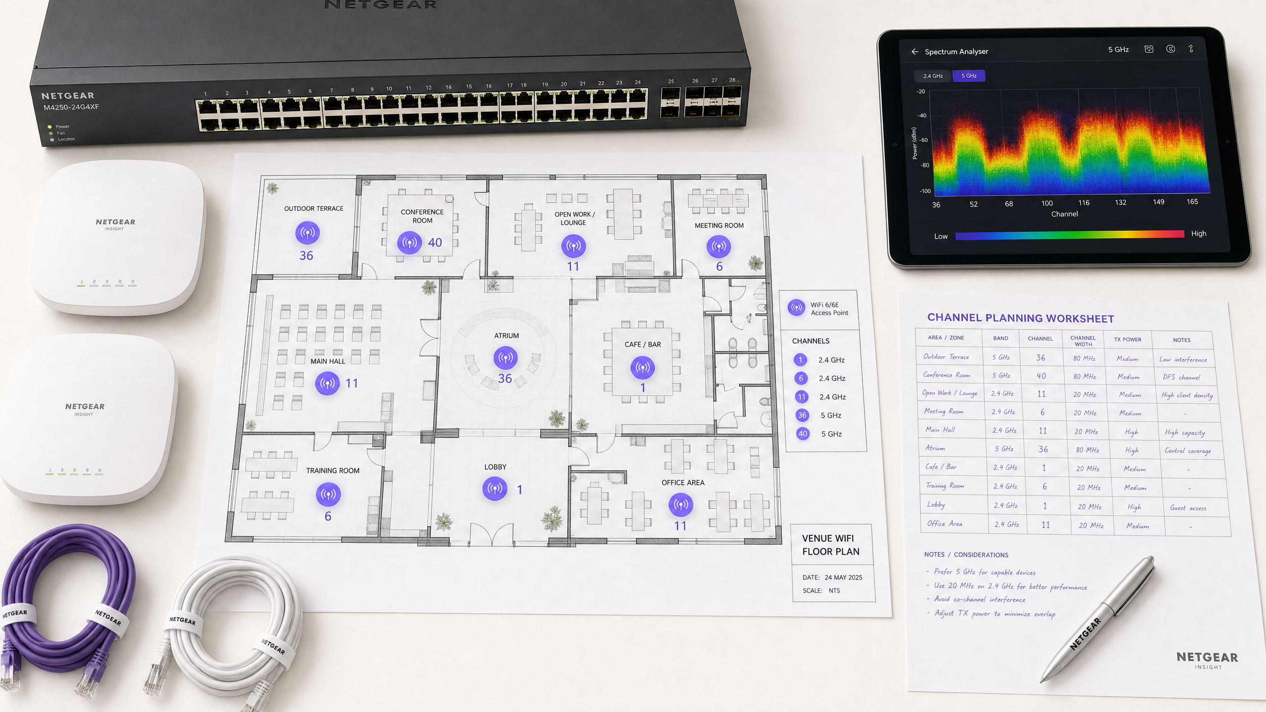
Étape 1 : Effectuer une analyse du spectre
Avant d'apporter toute modification de configuration, établissez une base de référence empirique. Déployez un analyseur de spectre — soit un matériel dédié, soit les outils intégrés de votre contrôleur WLAN d'entreprise — pour sonder l'environnement RF sur les deux bandes. Documentez les éléments suivants : les AP non autorisés ou voisins et leurs attributions de canaux, le plancher de bruit sur chaque canal, la présence de sources d'interférences non-WiFi et les niveaux de puissance de transmission actuels des AP. Cette base de référence est votre point de référence pour mesurer l'impact des changements ultérieurs.
Étape 2 : Formuler un plan de canaux
Pour la bande 2,4 GHz : Restreignez strictement le pool de canaux aux canaux 1, 6 et 11. Définissez toutes les largeurs de canal à 20 MHz — c'est non négociable. Si la densité d'AP est suffisamment élevée pour provoquer un CCI significatif même avec le schéma 1-6-11, envisagez de désactiver la radio 2,4 GHz sur des AP alternés selon un motif en damier, réduisant ainsi de moitié la densité d'AP 2,4 GHz tout en maintenant la couverture via les AP restants.
Pour la bande 5 GHz : Maximisez l'utilisation des canaux non superposés disponibles. Dans les déploiements à haute densité — centres de conférence, stades, pôles de Transport — imposez des largeurs de canal de 20 MHz pour maximiser le nombre de canaux indépendants. N'augmentez à 40 MHz que dans les zones à faible densité où l'interférence co-canal (ICC) n'est pas un problème. Évaluez attentivement l'inclusion des canaux DFS en fonction de votre emplacement spécifique et de la proximité des sources radar. Consultez la liste de disponibilité des canaux de votre autorité réglementaire nationale pour votre région spécifique.
Étape 3 : Configurer les points d'accès
Accédez à votre contrôleur de réseau local sans fil (WLC) ou à votre tableau de bord de gestion cloud pour appliquer le plan de canaux. La plupart des plateformes d'entreprise offrent des fonctionnalités de gestion des ressources radio (RRM) ou Auto-RF qui attribuent dynamiquement les canaux et les niveaux de puissance.
| Approche | Idéal pour | Risque |
|---|---|---|
| Plan statique manuel | Sites complexes, à haute densité ou adjacents à un radar | Nécessite une nouvelle étude périodique à mesure que l'environnement change |
| Auto-RF / RRM | Déploiements plus simples, à faible densité | Peut provoquer une instabilité des canaux dans des environnements RF volatils |
| Hybride | La plupart des déploiements d'entreprise | Nécessite une configuration de contraintes minutieuse |
Dans les environnements très complexes, un plan de canaux statique manuel basé sur une étude prédictive offre généralement une meilleure stabilité que de se fier uniquement à l'Auto-RF. La puissance de transmission doit être ajustée en parallèle — réduisez la puissance TX des AP à 10–14 dBm sur 5 GHz dans les déploiements denses pour réduire la taille des cellules et l'interférence entre les AP.
Étape 4 : Valider et surveiller
Après avoir appliqué les modifications, effectuez une étude de validation post-implémentation pour valider le nouveau plan de canaux. Surveillez les indicateurs clés de performance (KPI) via votre plateforme WiFi Analytics , en vous concentrant sur les taux de réessai, l'utilisation du temps d'antenne par AP, le nombre d'associations client et le comportement d'itinérance. Un environnement RF bien réglé devrait afficher des taux de réessai inférieurs à 10 % et une utilisation du temps d'antenne inférieure à 70 % pendant les périodes de pointe.
Bonnes pratiques
Imposez des largeurs de 20 MHz en haute densité. Dans des environnements comme les centres de conférence ou les stades, privilégiez la capacité — plus de canaux non superposés — plutôt que le débit maximal d'un seul client provenant de canaux plus larges. La performance globale du réseau sera significativement plus élevée.
Mettez en œuvre le band steering de manière agressive. Configurez le band steering pour éloigner les clients compatibles 5 GHz de la bande 2,4 GHz encombrée. La plupart des contrôleurs d'entreprise modernes prennent en charge cette fonctionnalité nativement. Réservez la bande 2,4 GHz aux appareils IoT et au matériel hérité qui ne peuvent pas fonctionner sur 5 GHz.
Désactivez les débits de données hérités. Désactivez les débits de données 802.11b (1, 2, 5.5, 11 Mbps) sur tous les SSIDs. Ces débits hérités consomment un temps d'antenne disproportionné et ralentissent l'ensemble du réseau. La définition d'un débit de données minimum de 12 ou 24 Mbps force les clients à se déplacer plus tôt et réduit la surcharge des trames de gestion.
Planifiez des audits RF réguliers. L'environnement RF est dynamique. Les nouveaux réseaux voisins, les modifications de bâtiments et les nouveaux équipements modifient tous le paysage des interférences. Planifiez des audits RF trimestriels pour maintenir votre plan de canaux à jour.
Intégrez la sécurité et la gestion du réseau. Assurez-vous que la détection et l'atténuation des AP non autorisés sont activées pour empêcher les appareils non autorisés de provoquer des interférences ou des failles de sécurité. Pour un contexte de sécurité réseau plus large, y compris le filtrage de contenu sur les réseaux invités, consultez Qu'est-ce que le filtrage DNS ? Comment bloquer le contenu nuisible sur le WiFi invité . Pour les stratégies d'optimisation spécifiques aux bureaux, consultez Office Wi Fi : Optimisez votre réseau Wi-Fi de bureau moderne .
Dépannage et atténuation des risques
Symptôme : Signal fort, faible débit. C'est la marque de l'interférence co-canal (ICC). Le plancher de bruit est faible mais le temps d'antenne est saturé. Auditez les attributions de canaux et la puissance de transmission des AP. Réduisez la puissance TX et imposez des largeurs de canal de 20 MHz pour libérer du temps d'antenne et améliorer la réutilisation spatiale.
Symptôme : Déconnexions aléatoires de clients dans des zones spécifiques. Vérifiez immédiatement les journaux d'événements DFS. Si les AP de cette zone sont sur des canaux UNII-2 ou UNII-2e et se trouvent à proximité d'une source radar, ils seront légalement tenus de quitter le canal, déconnectant les clients. Excluez ces canaux DFS spécifiques du plan de canaux pour les zones affectées.
Symptôme : Le plan de canaux change automatiquement. Il s'agit d'une instabilité des canaux causée par un algorithme Auto-RF trop sensible réagissant à des interférences transitoires. Limitez les paramètres de sensibilité RRM, augmentez le temporisateur de maintien (hold-down timer) ou migrez vers un plan de canaux statique basé sur les données d'enquête.
Symptôme : Mauvaise performance dans des zones spécifiques malgré un bon signal. Des interférences non-WiFi provenant de fours à micro-ondes, de téléphones DECT ou d'équipements industriels peuvent augmenter le plancher de bruit. Un analyseur de spectre identifiera ces sources. La solution consiste soit à supprimer la source, soit à migrer les AP affectés vers la bande 5 GHz ou 6 GHz, qui est immunisée contre la plupart des interféreurs 2,4 GHz non-WiFi.
ROI et impact commercial
L'optimisation des canaux WiFi est une mise à niveau d'infrastructure sans coût qui génère des retours immédiats et mesurables. Les organisations qui mettent en œuvre une planification appropriée des canaux RF signalent généralement une réduction de 30 à 40 % des tickets d'assistance liés au WiFi au cours du premier trimestre. Dans les environnements de Santé , un environnement RF correctement réglé assure un flux ininterrompu de données de télémétrie critiques et prend en charge la conformité aux exigences de communication des dispositifs cliniques. Dans le Commerce de détail , il garantit le fonctionnement transparent des systèmes de point de vente mobiles, des analyses de localisation précises et des applications de gestion des stocks fiables.
Du point de vue des dépenses d'investissement, une planification correcte des canaux élimine fréquemment le besoin perçu de matériel AP supplémentaire. De nombreuses organisations qui pensent avoir une densité d'APLes problèmes d'ity ont en fait un problème de planification des canaux. Résoudre la configuration RF en premier — avant de se procurer du matériel supplémentaire — est une pratique courante dans toute évaluation de réseau rigoureuse. Un environnement RF correctement réglé prolonge également le cycle de vie opérationnel de l'infrastructure existante, reportant les cycles coûteux de renouvellement matériel et offrant un retour sur investissement direct et quantifiable sur le capital existant.
Définitions clés
Co-Channel Interference (CCI)
Interference that occurs when multiple access points or client devices transmit on the exact same frequency channel simultaneously.
Managed by CSMA/CA, but causes congestion and reduced throughput when excessive. The primary symptom is high airtime utilisation with low throughput.
Adjacent-Channel Interference (ACI)
Interference caused by devices transmitting on overlapping but non-identical frequency channels, creating RF noise that CSMA/CA cannot decode or manage.
More destructive than CCI. Raises the noise floor, causes packet loss, and forces retransmissions. Caused by using channels other than 1, 6, and 11 on 2.4 GHz.
Dynamic Frequency Selection (DFS)
An IEEE 802.11h mechanism that requires WiFi access points to monitor for radar signals on certain 5 GHz channels and immediately vacate the channel if radar is detected.
Affects UNII-2 and UNII-2e channels. Critical consideration for venues near airports, weather stations, or military sites, where frequent radar detection causes client disconnections.
Radio Resource Management (RRM)
Automated algorithms within enterprise WLAN controllers that dynamically adjust channel assignments and transmit power levels based on real-time RF conditions.
Useful for adapting to changing RF environments, but can cause 'channel churn' — frequent channel changes — in volatile environments, disrupting client connectivity.
Channel Bonding
The process of combining multiple adjacent 20 MHz channels into wider 40, 80, or 160 MHz channels to increase peak single-client throughput.
Reduces the total number of available non-overlapping channels, increasing CCI risk in dense deployments. Should be avoided in high-density enterprise environments.
Band Steering
A WLAN controller feature that encourages dual-band capable client devices to associate with the 5 GHz band rather than the congested 2.4 GHz band.
Essential for load balancing in enterprise deployments. Preserves the limited 2.4 GHz spectrum for IoT devices and legacy hardware that cannot operate on 5 GHz.
CSMA/CA
Carrier Sense Multiple Access with Collision Avoidance. The medium access control protocol used by IEEE 802.11 WiFi, requiring devices to listen for clear airtime before transmitting.
The mechanism that governs how WiFi devices share the RF medium. High CCI forces devices to wait longer for clear airtime, directly reducing throughput and increasing latency.
Noise Floor
The aggregate level of background RF energy present in a given frequency band, measured in dBm. A higher noise floor reduces the effective Signal-to-Noise Ratio (SNR) for WiFi transmissions.
Raised by ACI, non-WiFi interference, and poor channel planning. A high noise floor forces devices to use lower modulation schemes and data rates, reducing throughput.
Spatial Reuse
The ability of multiple access points to simultaneously transmit on the same channel without interfering with each other, enabled by physical separation and appropriate transmit power levels.
The fundamental mechanism that allows high-density WiFi networks to scale. Maximised by reducing AP transmit power and using the minimum necessary channel widths.
Exemples concrets
A 200-room hotel is experiencing widespread complaints of slow WiFi during the evening peak. The current deployment uses 40 MHz channels on the 2.4 GHz band across 80 APs, and Auto-RF is enabled. The WLAN controller logs show frequent channel changes throughout the evening.
Phase 1 — Immediate remediation: Reconfigure all 2.4 GHz radios to 20 MHz channel widths immediately. Restrict the 2.4 GHz channel pool to channels 1, 6, and 11 only within the controller. This alone will eliminate ACI across the deployment.
Phase 2 — Stabilise Auto-RF: Review the Auto-RF event logs. If APs are changing channels more than once per hour, the algorithm is reacting to transient interference. Increase the RRM hold-down timer and reduce the sensitivity threshold. If churn persists, migrate to a static channel plan.
Phase 3 — Band steering: Enable aggressive band steering to push dual-band devices to 5 GHz. This reduces 2.4 GHz load significantly during peak periods.
Phase 4 — Validation: Deploy a spectrum analyser post-change and monitor retry rates and airtime utilisation via the WiFi analytics dashboard for 48 hours to confirm improvement.
A large retail chain has deployed APs every 12 metres across a 4,000 sq metre distribution centre. Even on the 5 GHz band using 20 MHz channels, CCI is high, throughput is poor, and mobile scanning devices are experiencing frequent disconnections during peak shift hours.
Step 1 — Audit transmit power: The APs are almost certainly configured at maximum TX power (typically 20–23 dBm). At 12-metre spacing, this creates massive cell overlap. Reduce TX power to 10–12 dBm on 5 GHz to shrink cell sizes and reduce inter-AP interference.
Step 2 — Disable legacy data rates: Disable all 802.11b/g data rates below 12 Mbps. This forces scanning devices to roam to the nearest AP rather than staying associated with a distant AP at a low data rate, which consumes disproportionate airtime.
Step 3 — Review channel plan: Ensure the 5 GHz channel plan uses the maximum number of non-overlapping channels available. With high AP density, every unique channel matters.
Step 4 — Validate with post-change survey: Conduct a walkthrough survey with a spectrum analyser to confirm reduced inter-AP overlap and improved SNR across the floor.
Questions d'entraînement
Q1. You are deploying a new wireless network in a multi-tenant office building. Your spectrum scan shows heavy utilisation on channels 1, 6, and 11 from neighbouring tenants. A junior engineer suggests using channels 3, 8, and 13 to 'avoid the congestion'. How do you respond, and what is the correct configuration?
Conseil : Consider the difference between Co-Channel Interference (CCI) and Adjacent-Channel Interference (ACI), and which is more harmful to network performance.
Voir la réponse type
The junior engineer's suggestion is incorrect and would cause severe performance degradation. Channels 3, 8, and 13 overlap with channels 1, 6, and 11 respectively, which would introduce Adjacent-Channel Interference — the most destructive form of WiFi interference. ACI manifests as pure RF noise that CSMA/CA cannot manage, causing packet loss and retransmissions. The correct configuration is to deploy on channels 1, 6, and 11. While this will cause Co-Channel Interference with the neighbouring tenants, CSMA/CA can handle CCI gracefully by having devices take turns. The aggregate performance will be significantly better than with ACI.
Q2. A stadium deployment is using 80 MHz channels on the 5 GHz band to advertise 'Gigabit WiFi' speeds during events. Users report slow loading times, frequent disconnections, and poor video streaming quality during peak occupancy. The AP hardware is modern WiFi 6 equipment. What is the architectural flaw, and what is the remediation?
Conseil : Evaluate the trade-off between peak single-client throughput and overall network capacity in a high-density environment.
Voir la réponse type
The architectural flaw is the use of 80 MHz channel widths in a high-density environment. Each 80 MHz channel bonds four 20 MHz channels together, drastically reducing the total number of non-overlapping channels available across the deployment. With many APs forced to reuse the same wide channels, Co-Channel Interference becomes severe. The solution is to reduce channel widths to 20 MHz across all APs. This increases the number of independent channels available, reduces CCI, and significantly improves aggregate network capacity. The peak throughput per client will decrease, but the number of clients that can be served simultaneously — and the quality of their experience — will increase substantially.
Q3. Your hospital network experiences intermittent client disconnections affecting medical devices in wards near the hospital's rooftop helipad. The affected APs are configured to use channels 52, 56, 60, and 64. What is the most likely cause, and what is the correct remediation?
Conseil : Consider the regulatory requirements for the specific 5 GHz channels in use and what systems operate near a helipad.
Voir la réponse type
Channels 52, 56, 60, and 64 are UNII-2 DFS channels. The helicopters using the helipad, or associated aviation radar systems, are likely triggering DFS radar detection events on the APs in that zone. When radar is detected, the APs are legally required to immediately vacate those channels, causing client disconnections. The correct remediation is to exclude all DFS channels from the channel plan for APs in the zones near the helipad. Reconfigure those APs to use UNII-1 channels (36, 40, 44, 48) or UNII-3 channels (149, 153, 157, 161, 165), which are not subject to DFS requirements.