Concevoir une architecture WiFi multi-locataire pour les MDU
Ce guide de référence fournit un plan architectural pour le déploiement de réseaux WiFi évolutifs, sécurisés et isolés à travers plusieurs unités dans un MDU. Il couvre des considérations critiques telles que la segmentation VLAN, la planification RF, l'authentification 802.1X, et comment équilibrer l'isolation des locataires avec une gestion centralisée pour un ROI amélioré.
Écouter ce guide
Voir la transcription du podcast
Résumé Exécutif
Pour les CTO et les architectes principaux gérant des unités multi-résidentielles (MDU) — qu'il s'agisse de vastes complexes hôteliers, d'environnements commerciaux à usage mixte ou de logements du secteur public — le défi est constant : fournir une connectivité sécurisée et haute performance à des locataires indépendants sur une infrastructure physique partagée. Les conceptions de réseaux traditionnels à locataire unique s'effondrent sous le poids des exigences des MDU, entraînant des vulnérabilités de sécurité, une saturation du domaine de diffusion et des frais de support ingérables.
Concevoir une architecture WiFi multi-locataire exige un passage de l'isolation physique à la segmentation logique. Ce guide de référence décrit le plan architectural définitif pour les déploiements MDU. Nous examinerons la mise en œuvre du marquage VLAN IEEE 802.1Q pour une isolation stricte du trafic, la nécessité de l'authentification RADIUS 802.1X pour le contrôle d'accès, et le rôle critique des contrôleurs cloud centralisés pour maintenir la visibilité opérationnelle. En adoptant ces principes neutres vis-à-vis des fournisseurs, les opérateurs de sites peuvent atténuer les risques de conformité (tels que PCI DSS et GDPR), réduire les dépenses opérationnelles et transformer la connectivité d'un centre de coûts en une couche de services monétisable.
Plongée Technique
La Fondation : Segmentation Logique via les VLAN
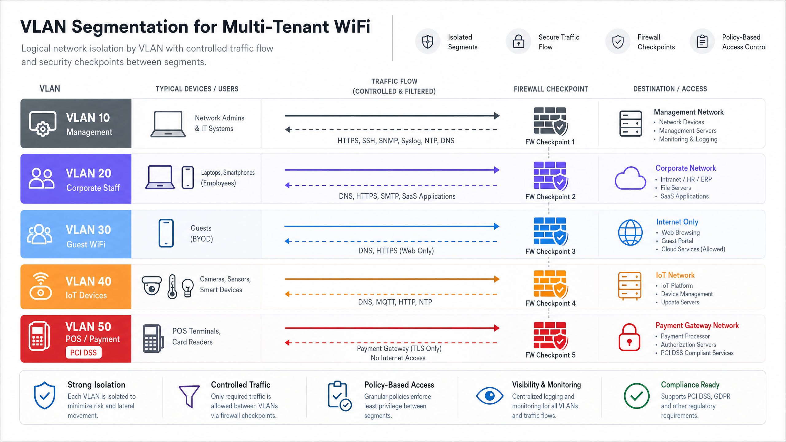
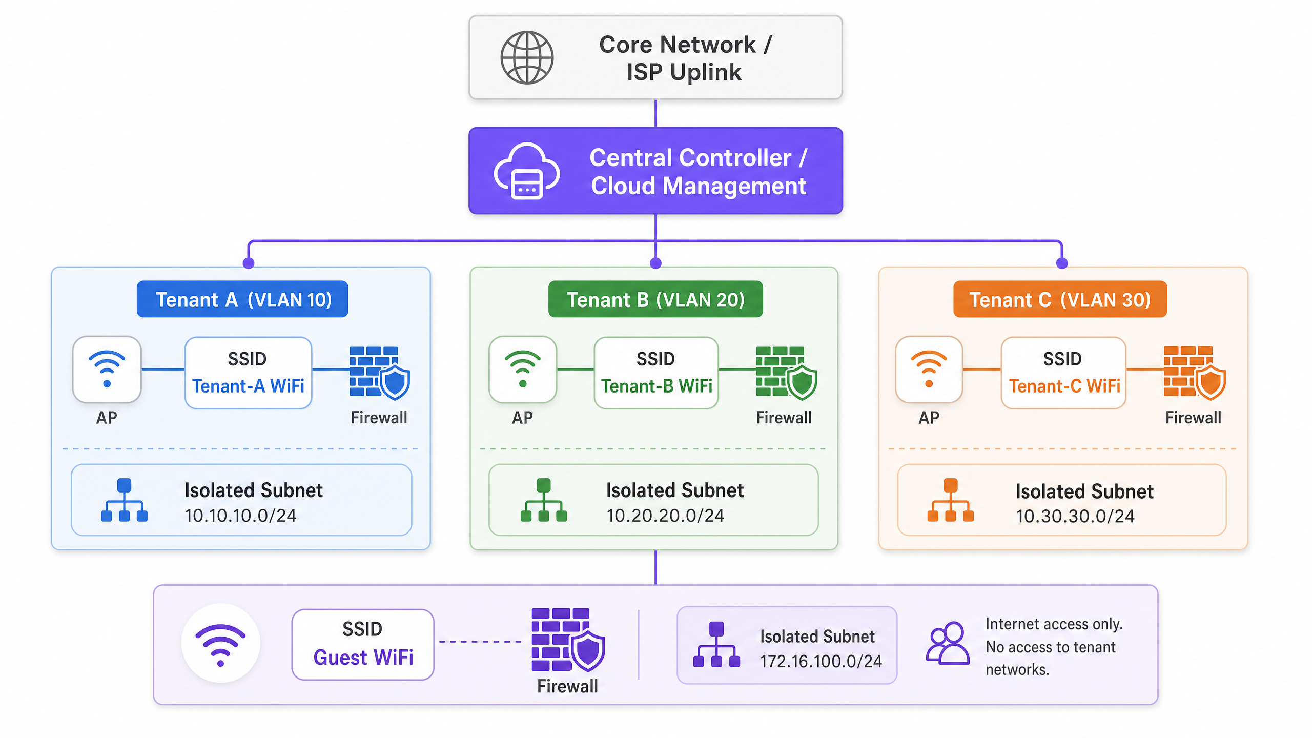
La pierre angulaire de toute architecture multi-locataire est une segmentation réseau rigoureuse. Dans un environnement physique partagé, le déploiement de commutateurs et de câblages séparés pour chaque locataire est commercialement irréalisable. Au lieu de cela, l'isolation est réalisée à la couche 2 en utilisant les réseaux locaux virtuels (VLAN) IEEE 802.1Q.
Dans ce modèle, un point d'accès (AP) unique diffuse plusieurs identifiants de service (SSID), ou utilise l'attribution dynamique de VLAN via RADIUS, pour servir différents profils de locataires. Lorsqu'un client s'associe au réseau, son trafic est marqué avec un ID VLAN spécifique à la périphérie de l'AP. Cette balise persiste lorsque la trame traverse les liens de jonction à travers le tissu de commutation partagé, garantissant que le Locataire A (par exemple, VLAN 10) reste entièrement isolé du Locataire B (par exemple, VLAN 20) au niveau de la couche liaison de données.
Cependant, les VLANs fournissent une isolation, pas une sécurité inhérente. Pour empêcher les mouvements latéraux entre les réseaux de locataires, le routage inter-VLAN doit être strictement contrôlé via des politiques de pare-feu au niveau de la couche de distribution ou de cœur. Une approche Zero Trust dicte que le trafic entre les VLAN de locataires est implicitement refusé sauf s'il est explicitement autorisé pour des services spécifiques et requis.
Normes d'Authentification et de Chiffrement
Pour les environnements multi-locataires de niveau entreprise, les clés pré-partagées (PSK) sont inadéquates. Elles sont facilement partagées, difficiles à renouveler sans impacter tous les utilisateurs, et n'offrent aucune responsabilité individuelle. La norme architecturale est IEEE 802.1X avec authentification RADIUS.
Sous 802.1X, chaque utilisateur ou appareil s'authentifie individuellement en utilisant des identifiants uniques ou des certificats numériques. Le serveur RADIUS non seulement valide l'identité, mais peut également transmettre des attributs spécifiques au fournisseur (VSA) à l'authentificateur (l'AP ou le commutateur), attribuant dynamiquement l'utilisateur à son VLAN désigné, quel que soit le SSID auquel il s'est connecté. Cela réduit considérablement la prolifération des SSID, ce qui est essentiel pour maintenir l'efficacité du temps d'antenne.
Pour le chiffrement, WPA3-Enterprise est le mandat actuel. Il fournit des suites de sécurité robustes de 192 bits pour les environnements hautement sensibles et atténue les attaques par dictionnaire hors ligne qui ont affligé WPA2.
Isolation des Invités et de l'IoT
Au-delà du trafic d'entreprise ou de locataires, les architectures MDU doivent prendre en compte deux profils de trafic distincts : les invités et les appareils de l'Internet des Objets (IoT).
- Réseaux Invités : Les invités nécessitent un accès internet sans friction mais doivent être entièrement séparés des données des locataires. Ceci est généralement géré via un Captive Portal. Pour des informations détaillées sur la gestion de cette couche et son utilisation pour l'intelligence économique, consultez notre aperçu complet du Guest WiFi et des capacités WiFi Analytics associées.
- Appareils IoT : Les MDU modernes sont fortement instrumentées avec des thermostats intelligents, des caméras IP et des systèmes de gestion de bâtiment. Ces appareils sont souvent sans tête, difficiles à patcher et représentent une surface d'attaque significative. Ils doivent être isolés sur des VLAN IoT dédiés avec un filtrage de sortie strict, n'autorisant la communication qu'avec des serveurs de gestion spécifiques.
Guide d'Implémentation
Le déploiement de cette architecture nécessite une approche méthodique, passant de la conception logique à la validation physique.
Phase 1 : Conception du Réseau Logique
Commencez par définir le schéma d'adressage IP et le mappage VLAN. Une approche structurée prévient les chevauchements de sous-réseaux et simplifie le routage.
- VLAN de Gestion (par exemple, VLAN 1) : Strictement pour l'infrastructure réseau (APs, commutateurs). Pas d'accès utilisateur.
- VLAN de Locataires (par exemple, VLANs 100-199) : Sous-réseaux dédiés pour les locataires individuels ou les unités commerciales.
- VLAN Invité (par exemple, VLAN 200) : Accès Internet uniquement, fortement restreint.
- VLAN IoT/Installations (par exemple, VLAN 300) : Pour les systèmes de gestion de bâtiment.
Phase 2 : Planification RF et Étude de Site
Dans les environnements à haute densité comme l' Hôtellerie ou le Commerce de Détail , l'interférence co-canal (CCI) est la principale cause de mauvaises performances. Une étude prédictive est insuffisante ; une étude RF active sur site est obligatoire pour tenir compte de l'atténuation des murs et des interférences voisines.
- Préférence 5 GHz / 6 GHz : Poussez les clients vers la bande 5 GHz, ou 6 GHz si vous utilisez le Wi-Fi 6E, pour exploiter davantage de canaux non superposés. Pour une compréhension plus approfondie de la gestion du spectre, consultez notre guide sur les Fréquences Wi-Fi : Un Guide du Wi-Fi Fréquences en 2026 .
- Largeurs de canal : Dans les MDU denses, limitez les largeurs de canal à 20 MHz sur la bande 2,4 GHz et à 40 MHz sur la bande 5 GHz afin de maximiser la réutilisation des canaux.
- Si vous rencontrez des problèmes de performance dans un déploiement existant, consultez Comment analyser et modifier votre canal WiFi pour une vitesse maximale (ou la version italienne : Come analizzare e modificare il canale WiFi per la massima velocità ).
Phase 3 : Configuration de l'infrastructure
- Fabric de commutation : Configurez méticuleusement les ports trunk. Assurez-vous que seuls les VLAN requis sont autorisés sur les liaisons montantes entre les commutateurs d'accès et le cœur de réseau.
- Points d'accès : Déployez des APs capables de prendre en charge plusieurs BSSID et de s'intégrer à un contrôleur cloud. Limitez le nombre de SSIDs diffusés à un maximum de 3-4 par radio pour préserver le temps d'antenne.
- Politiques du contrôleur : Définissez des limites de bande passante par locataire ou par utilisateur pour éviter qu'un seul client agressif ne sature la liaison montante WAN partagée.
Bonnes pratiques
- Gestion centralisée dans le cloud : La charge opérationnelle de la gestion d'un environnement MDU distribué sans une vue d'ensemble unique est insoutenable. Un contrôleur cloud permet le provisionnement sans contact, la gestion du micrologiciel et l'application centralisée des politiques.
- Attribution dynamique de VLAN : Plutôt que de diffuser « Tenant_A_WiFi », « Tenant_B_WiFi », etc., diffusez un seul SSID « MDU_Secure » et utilisez 802.1X/RADIUS pour placer dynamiquement les utilisateurs authentifiés dans leur VLAN correct. Cela réduit considérablement la surcharge des balises.
- Services basés sur la localisation : Tirez parti du BLE (Bluetooth Low Energy) intégré aux APs modernes pour le suivi des actifs ou l'orientation. Pour en savoir plus, lisez BLE Low Energy Explained for Enterprise .
- Optimiser pour l'environnement : L'agencement physique d'un espace de bureau MDU nécessite un réglage spécifique. Reportez-vous à Office Wi Fi: Optimize Your Modern Office Wi-Fi Network pour des ajustements spécifiques à l'environnement.
Dépannage et atténuation des risques
Modes de défaillance courants
- Mauvaise configuration du port Trunk : La cause la plus fréquente de « connecté, pas d'internet » dans les configurations multi-locataires. Si un VLAN est manquant sur une liaison trunk entre l'AP et la passerelle, les requêtes DHCP échoueront.
- Atténuation : Mettez en œuvre un audit de configuration automatisé et documentez rigoureusement la topologie de l'arbre recouvrant.
- Surcharge SSID : Diffuser 10 SSIDs sur un seul AP signifie que la radio passe un pourcentage significatif de son temps à simplement transmettre des trames de balise, laissant peu de temps d'antenne pour les données réelles.
- Atténuation : Consolidez les SSIDs et utilisez l'attribution dynamique de VLAN.
- Exposition du plan de gestion : Si un locataire peut « pinger » ou accéder à l'interface de gestion d'un AP ou d'un commutateur, le réseau est fondamentalement compromis.
- Atténuation : Utilisez un VLAN de gestion dédié, hors bande, et appliquez des listes de contrôle d'accès (ACL) strictes bloquant tout trafic RFC 1918 des sous-réseaux des locataires vers le sous-réseau de gestion.
ROI et impact commercial
La transition vers une architecture multi-locataire robuste transforme le réseau d'un mal nécessaire en un atout stratégique.
- Réduction des OpEx : La gestion centralisée et la segmentation logique réduisent le besoin de déplacements sur site. Les services d'assistance peuvent diagnostiquer les problèmes à distance, identifiant si une défaillance réside dans l'infrastructure partagée ou dans la configuration spécifique du locataire.
- Conformité et réduction des risques : En isolant les données de l'industrie des cartes de paiement (PCI) (par exemple, dans les unités de vente au détail) ou les données sensibles des patients (par exemple, dans les installations Healthcare situées dans des bâtiments à usage mixte), le champ des audits de conformité est considérablement réduit, ce qui permet d'économiser des frais de conseil importants.
- Monétisation : Avec une architecture stable et segmentée, les opérateurs de sites peuvent proposer des forfaits de bande passante échelonnés aux locataires, générant ainsi des revenus récurrents. De plus, le réseau invité peut être exploité pour la capture de données et le marketing, transformant le trafic piétonnier en informations exploitables.
Écoutez notre podcast de briefing technique ci-dessous pour une discussion approfondie sur ces principes architecturaux :
Définitions clés
VLAN (Virtual Local Area Network)
A logical grouping of network devices that appear to be on the same local LAN, regardless of their physical location.
Used in MDUs to logically separate traffic from different tenants sharing the same physical switches and APs, reducing broadcast traffic and improving performance.
IEEE 802.1Q
The networking standard that supports VLANs on an Ethernet network by inserting a 32-bit tag into the Ethernet frame.
This is the underlying protocol that allows a single trunk cable to carry traffic for multiple isolated tenant networks.
IEEE 802.1X
An IEEE standard for port-based network access control (PNAC), providing an authentication mechanism to devices wishing to attach to a LAN or WLAN.
Essential for enterprise MDU deployments, it allows individual user authentication (via RADIUS) rather than relying on a shared password, enabling dynamic VLAN assignment.
RADIUS (Remote Authentication Dial-In User Service)
A networking protocol that provides centralised Authentication, Authorization, and Accounting (AAA) management for users who connect and use a network service.
The server component in an 802.1X deployment that verifies credentials and tells the AP which VLAN to assign the tenant device to.
Trunk Port
A network switch port configured to carry traffic for multiple VLANs simultaneously, using 802.1Q tags to keep the traffic separated.
The critical link between access switches and the core network. Misconfiguring a trunk port is the most common cause of tenant connectivity failure.
Co-Channel Interference (CCI)
Interference that occurs when two or more access points are transmitting on the exact same frequency channel within hearing distance of each other.
A major issue in dense MDUs (like hotels or apartment blocks) that causes devices to wait for the channel to clear, drastically reducing network throughput.
Dynamic VLAN Assignment
The process where a RADIUS server instructs the network access device (AP or switch) to place an authenticated user into a specific VLAN based on their identity.
Allows venue operators to broadcast a single secure SSID for all tenants, assigning them to their isolated networks post-authentication, thereby saving RF airtime.
Captive Portal
A web page that the user of a public-access network is obliged to view and interact with before access is granted.
Used on the Guest VLAN in an MDU to enforce terms of service, collect marketing data, or process payments before granting internet access.
Exemples concrets
A mixed-use retail and office complex (MDU) needs to provide secure WiFi for 15 independent retail tenants, a shared corporate office space, and public guest WiFi. The venue operator wants to use a single physical network infrastructure to reduce costs but must ensure PCI DSS compliance for the retailers.
- Deploy enterprise-grade APs managed by a central cloud controller.
- Create a 'Management' VLAN (VLAN 10) strictly for network devices.
- Create a 'Guest' VLAN (VLAN 20) with client isolation enabled and a captive portal. Route this traffic directly to the internet, bypassing internal networks.
- For the office space, create a 'Corporate' VLAN (VLAN 30) using 802.1X authentication.
- For the retail tenants, implement Dynamic VLAN Assignment. Broadcast a single 'Retail_Secure' SSID using 802.1X. When a retail device authenticates via the central RADIUS server, the server passes a Vendor-Specific Attribute (VSA) that assigns the device to its specific tenant VLAN (e.g., VLANs 101-115).
- Configure the core firewall to block all inter-VLAN routing between the retail VLANs, ensuring strict isolation required for PCI DSS.
A 400-room hotel ([Hospitality](/industries/hospitality)) is upgrading its network. They need to support guest devices, staff tablets for housekeeping, and new IoT smart thermostats in every room. They currently experience frequent dropouts during peak evening hours.
- Conduct an active RF site survey to identify interference and plan AP placement (likely moving from hallway deployments to in-room or every-other-room deployments to handle density).
- Segment traffic logically: Guest (VLAN 100), Staff (VLAN 200), IoT (VLAN 300).
- Implement per-user bandwidth limiting on the Guest SSID (e.g., 10 Mbps down / 5 Mbps up) to prevent a few heavy users from saturating the WAN link during peak hours.
- For the IoT thermostats, use a dedicated hidden SSID with WPA3-Personal (if supported) or MAC Authentication Bypass (MAB) if they lack advanced supplicants. Apply strict egress filtering on VLAN 300 so thermostats can only communicate with the specific cloud management server.
Questions d'entraînement
Q1. You are designing the WiFi architecture for a new 50-unit premium apartment complex. The developer wants to offer 'Included Gigabit WiFi' as a selling point. They propose installing a standard consumer-grade wireless router in the telecom closet of each apartment, all wired back to a central unmanaged switch. What are the primary architectural flaws with this proposal, and what is the enterprise alternative?
Conseil : Consider RF interference, management overhead, and broadcast domain size.
Voir la réponse type
The proposed design has severe flaws. 1) RF Interference: 50 independent consumer routers will cause massive Co-Channel Interference (CCI), severely degrading performance. 2) Management: There is no central visibility; troubleshooting requires accessing 50 individual routers. 3) Security: An unmanaged switch means all apartments share a single broadcast domain, allowing tenants to potentially intercept each other's traffic.
The enterprise alternative is to deploy centrally managed, enterprise-grade APs (e.g., Wi-Fi 6/6E) in the apartments, connected to managed PoE switches. Implement 802.1X authentication with Dynamic VLAN Assignment so each tenant is logically isolated on their own VLAN, regardless of which AP they connect to. This provides central visibility, RF coordination, and strict security isolation.
Q2. During the commissioning phase of a multi-tenant office building, Tenant A (on VLAN 10) reports they cannot access the internet. You verify that the AP is broadcasting the SSID, the client connects successfully, and 802.1X authentication passes. However, the client device is assigning itself an APIPA address (169.254.x.x). What is the most likely configuration error in the infrastructure?
Conseil : Follow the path of the DHCP request from the AP to the DHCP server.
Voir la réponse type
The most likely issue is a misconfigured trunk port between the Access Point and the Access Switch, or between the Access Switch and the Core/Distribution switch. Because the client receives an APIPA address, the DHCP Discover broadcast is not reaching the DHCP server. If authentication passes, the RADIUS server is correctly assigning VLAN 10, but if VLAN 10 is not explicitly permitted on the 802.1Q trunk links along the path, the traffic is dropped at the switch port. The engineer must verify the 'switchport trunk allowed vlan' configuration on all uplinks.
Q3. A stadium ([Transport](/industries/transport) hub / event space) requires a multi-tenant network for operations staff, ticketing vendors, and public guest WiFi. To save time, the junior engineer suggests creating three SSIDs using WPA2-PSK, with a different password for each group. Why is this unacceptable for the ticketing vendors, and what must be implemented instead?
Conseil : Consider compliance requirements for processing payments.
Voir la réponse type
Using WPA2-PSK is unacceptable for ticketing vendors because they process payments, making them subject to PCI DSS (Payment Card Industry Data Security Standard) compliance. PSKs offer weak security, are easily shared, and do not provide individual user accountability. Furthermore, a shared PSK network does not inherently prevent devices from communicating with each other (client isolation).
Instead, the architecture must implement 802.1X with RADIUS authentication (preferably using WPA3-Enterprise) to provide individual, auditable access. The ticketing vendors must be placed on a dedicated, strictly isolated VLAN, with core firewall rules explicitly denying any routing between the ticketing VLAN and the guest or operations VLANs.